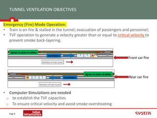
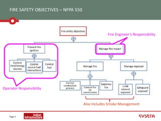
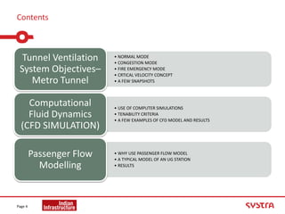
1. The document discusses a presentation on tunnel ventilation system design for smoke control using performance-based approaches. It focuses on metro tunnels and underground stations.
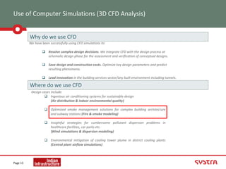
2. Computational fluid dynamics (CFD) simulations are used to model smoke and airflow in tunnels and stations under normal, congested, and emergency fire conditions. CFD helps establish ventilation system capacities and ensure critical smoke velocities are achieved.
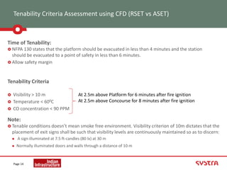
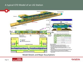
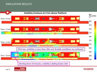
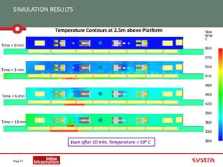
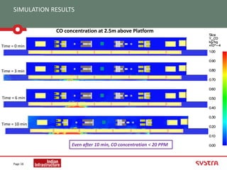
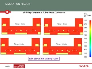
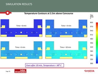
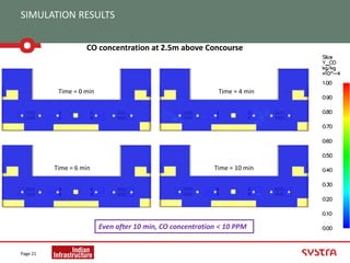
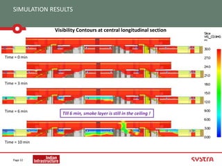
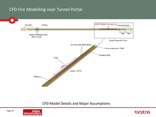
3. Tenability criteria of visibility, temperature, and carbon monoxide levels are assessed using CFD simulations to determine safe evacuation times and verify smoke control system designs. Examples of CFD models and results for an underground station are shown.

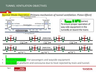
![TUNNEL VENTILATION OBJECTIVES
Page 7
Congested Mode Operation (No Piston Effect):
• Occurs when operational problem prevent the “normal” movement of trains
and trains may wait at stations or in the tunnel.
No threat/danger to Passengers; Evacuation not necessary;
• Operation of TVS (Push-Pull) to ensure tunnel temperature within operating
limits of the train air conditioning equipment. [ Generally, Tavg <460C].](https://image.slidesharecdn.com/metrotunnelventilaiton-230824102517-690665ec/85/Metro-tunnel-ventilaiton-pptx-7-320.jpg)