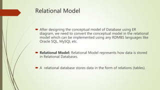
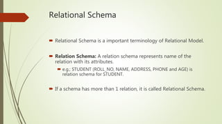
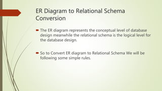
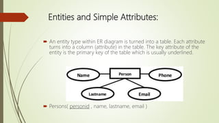
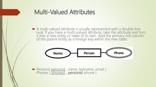
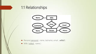
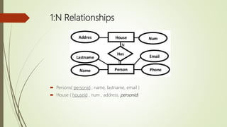
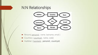
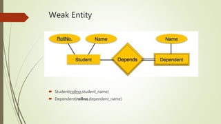
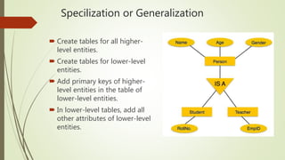
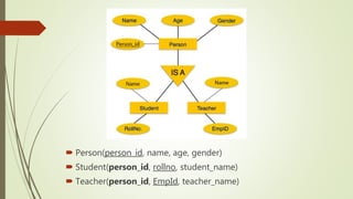
Welcome to our
Presentation
Presentation Topic: Relational Schema
Group Members
 Rifat Rahman ID: 162-15-1049
 Hasan Haider ID: 162-15-1041
 Arifur Jaman ID: 153-15-607
 Shahedul Islam ID: 162-15-1029
 Mohammad Salim Hosen ID: 162-15-1044
Relational Model
 After designing the conceptual model of Database using ER
diagram, we need to convert the conceptual model in the relational
model which can be implemented using any RDMBS languages like
Oracle SQL, MySQL etc.
 Relational Model: Relational Model represents how data is stored
in Relational Databases.
 A relational database stores data in the form of relations (tables).
Relational Schema
 Relational Schema is a important terminology of Relational Model.
 Relation Schema: A relation schema represents name of the
relation with its attributes.
 e.g.; STUDENT (ROLL_NO, NAME, ADDRESS, PHONE and AGE) is
relation schema for STUDENT.
 If a schema has more than 1 relation, it is called Relational Schema.
ER Diagram to Relational Schema
Conversion
 The ER diagram represents the conceptual level of database
design meanwhile the relational schema is the logical level for
the database design.
 So to Convert ER diagram to Relational Schema We will be
following some simple rules.
Entities and Simple Attributes:
 An entity type within ER diagram is turned into a table. Each attribute
turns into a column (attribute) in the table. The key attribute of the
entity is the primary key of the table which is usually underlined.
 Persons( personid , name, lastname, email )
Multi-Valued Attributes
 A multi-valued attribute is usually represented with a double-line
oval. If you have a multi-valued attribute, take the attribute and turn
it into a new entity or table of its own. Add the primary (id) column
of the parent entity as a foreign key within the new table.
 Persons( personid , name, lastname, email )
Phones ( phoneid , personid, phone )
1:1 Relationships
 Persons( personid , name, lastname, email , wifeid )
 Wife ( wifeid , name )
1:N Relationships
 Persons( personid , name, lastname, email )
 House ( houseid , num , address, personid)
N:N Relationships
 Persons( personid , name, lastname, email )
 Countries ( countryid , name, code)
 HasRelat ( hasrelatid , personid , countryid)
Weak Entity
 Student(rollno,student_name)
 Dependent(rollno,dependent_name)
Specilization or Generalization
 Create tables for all higher-
level entities.
 Create tables for lower-level
entities.
 Add primary keys of higher-
level entities in the table of
lower-level entities.
 In lower-level tables, add all
other attributes of lower-level
entities.
 Person(person_id, name, age, gender)
 Student(person_id, rollno, student_name)
 Teacher(person_id, EmpId, teacher_name)
THANK YOU

Presentation on Relational Schema (Database)

  • 1.
  • 2.
    Group Members  RifatRahman ID: 162-15-1049  Hasan Haider ID: 162-15-1041  Arifur Jaman ID: 153-15-607  Shahedul Islam ID: 162-15-1029  Mohammad Salim Hosen ID: 162-15-1044
  • 3.
    Relational Model  Afterdesigning the conceptual model of Database using ER diagram, we need to convert the conceptual model in the relational model which can be implemented using any RDMBS languages like Oracle SQL, MySQL etc.  Relational Model: Relational Model represents how data is stored in Relational Databases.  A relational database stores data in the form of relations (tables).
  • 4.
    Relational Schema  RelationalSchema is a important terminology of Relational Model.  Relation Schema: A relation schema represents name of the relation with its attributes.  e.g.; STUDENT (ROLL_NO, NAME, ADDRESS, PHONE and AGE) is relation schema for STUDENT.  If a schema has more than 1 relation, it is called Relational Schema.
  • 5.
    ER Diagram toRelational Schema Conversion  The ER diagram represents the conceptual level of database design meanwhile the relational schema is the logical level for the database design.  So to Convert ER diagram to Relational Schema We will be following some simple rules.
  • 6.
    Entities and SimpleAttributes:  An entity type within ER diagram is turned into a table. Each attribute turns into a column (attribute) in the table. The key attribute of the entity is the primary key of the table which is usually underlined.  Persons( personid , name, lastname, email )
  • 7.
    Multi-Valued Attributes  Amulti-valued attribute is usually represented with a double-line oval. If you have a multi-valued attribute, take the attribute and turn it into a new entity or table of its own. Add the primary (id) column of the parent entity as a foreign key within the new table.  Persons( personid , name, lastname, email ) Phones ( phoneid , personid, phone )
  • 8.
    1:1 Relationships  Persons(personid , name, lastname, email , wifeid )  Wife ( wifeid , name )
  • 9.
    1:N Relationships  Persons(personid , name, lastname, email )  House ( houseid , num , address, personid)
  • 10.
    N:N Relationships  Persons(personid , name, lastname, email )  Countries ( countryid , name, code)  HasRelat ( hasrelatid , personid , countryid)
  • 11.
    Weak Entity  Student(rollno,student_name) Dependent(rollno,dependent_name)
  • 12.
    Specilization or Generalization Create tables for all higher- level entities.  Create tables for lower-level entities.  Add primary keys of higher- level entities in the table of lower-level entities.  In lower-level tables, add all other attributes of lower-level entities.
  • 13.
     Person(person_id, name,age, gender)  Student(person_id, rollno, student_name)  Teacher(person_id, EmpId, teacher_name)
  • 14.