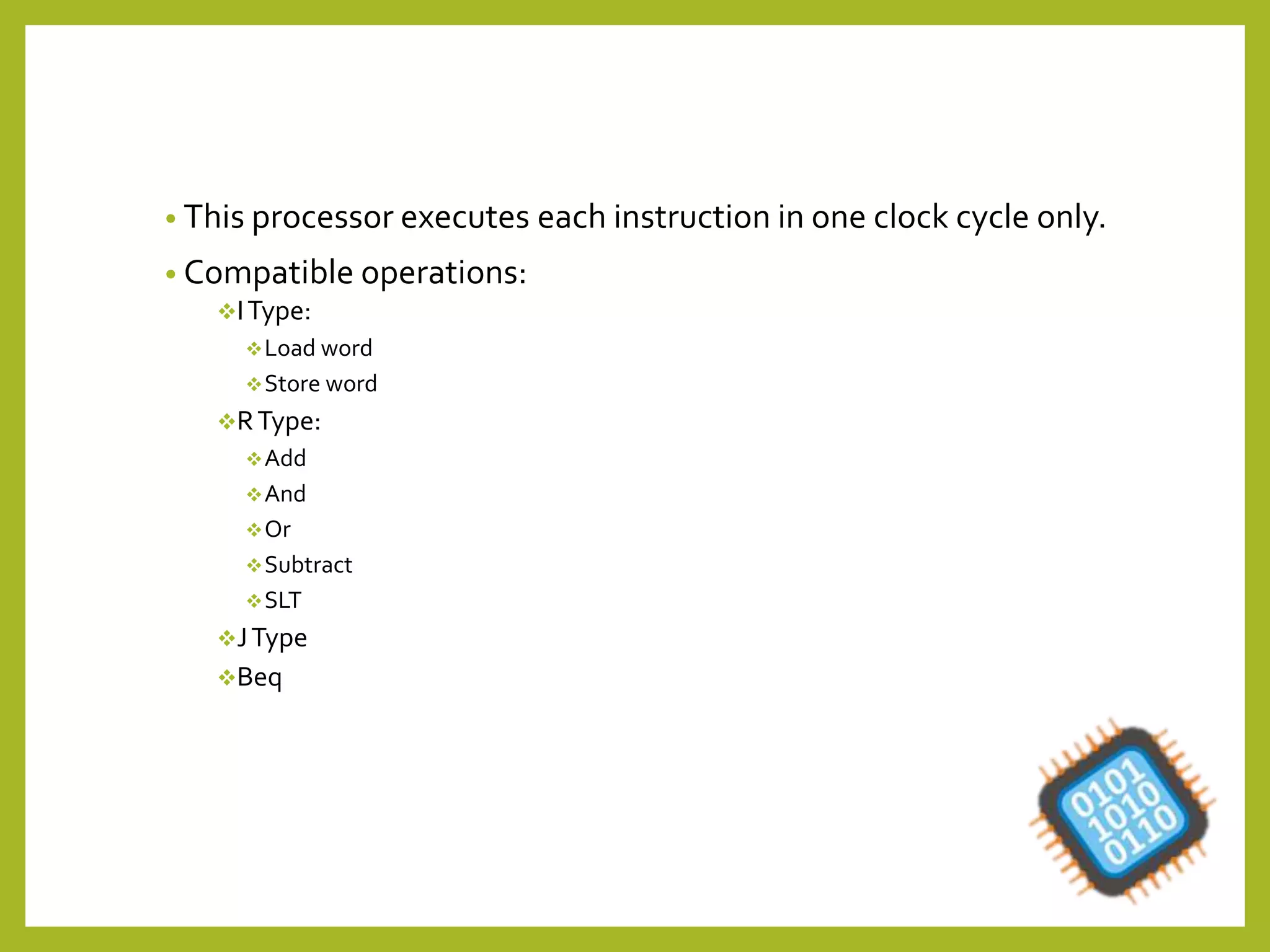
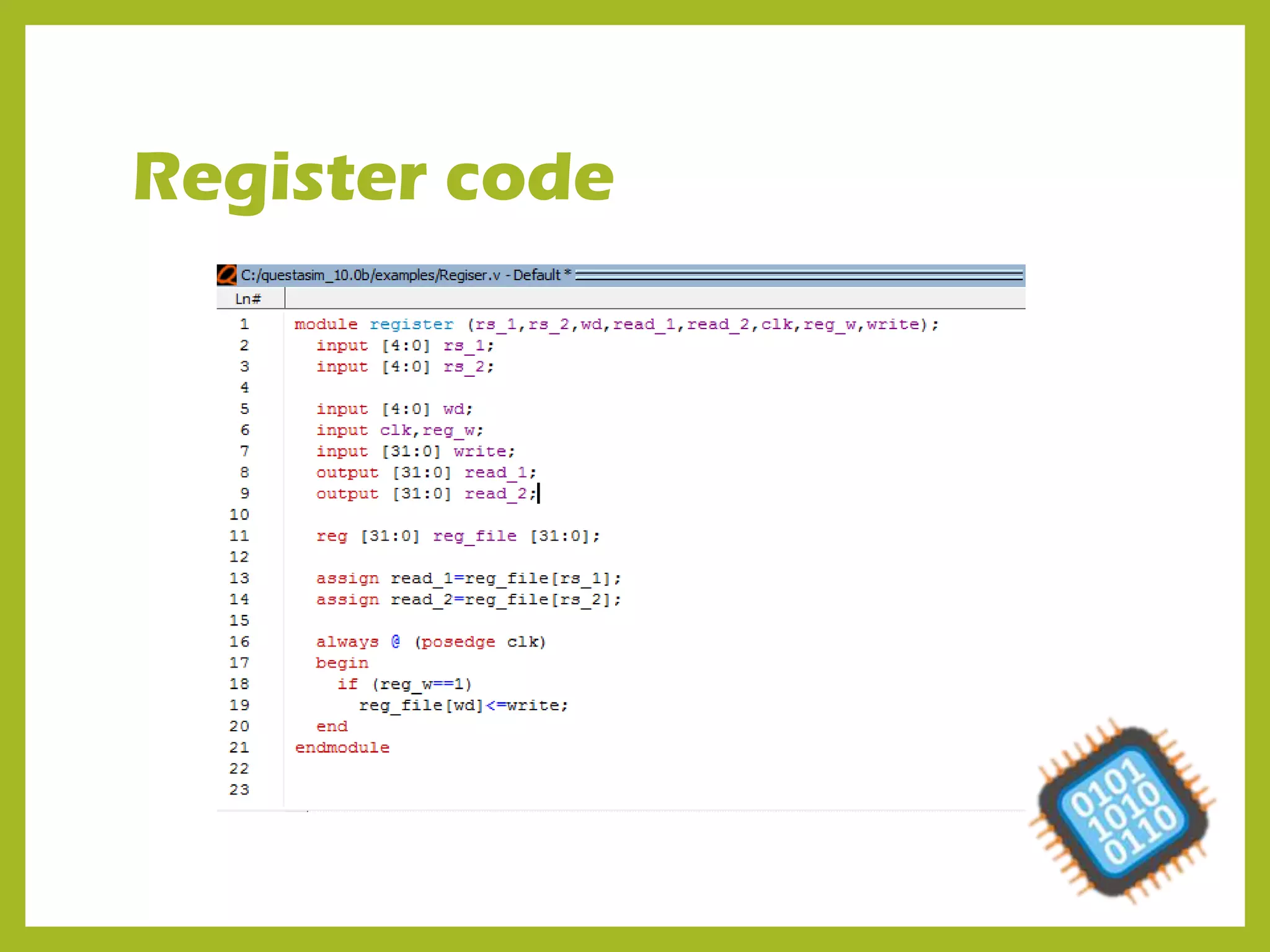
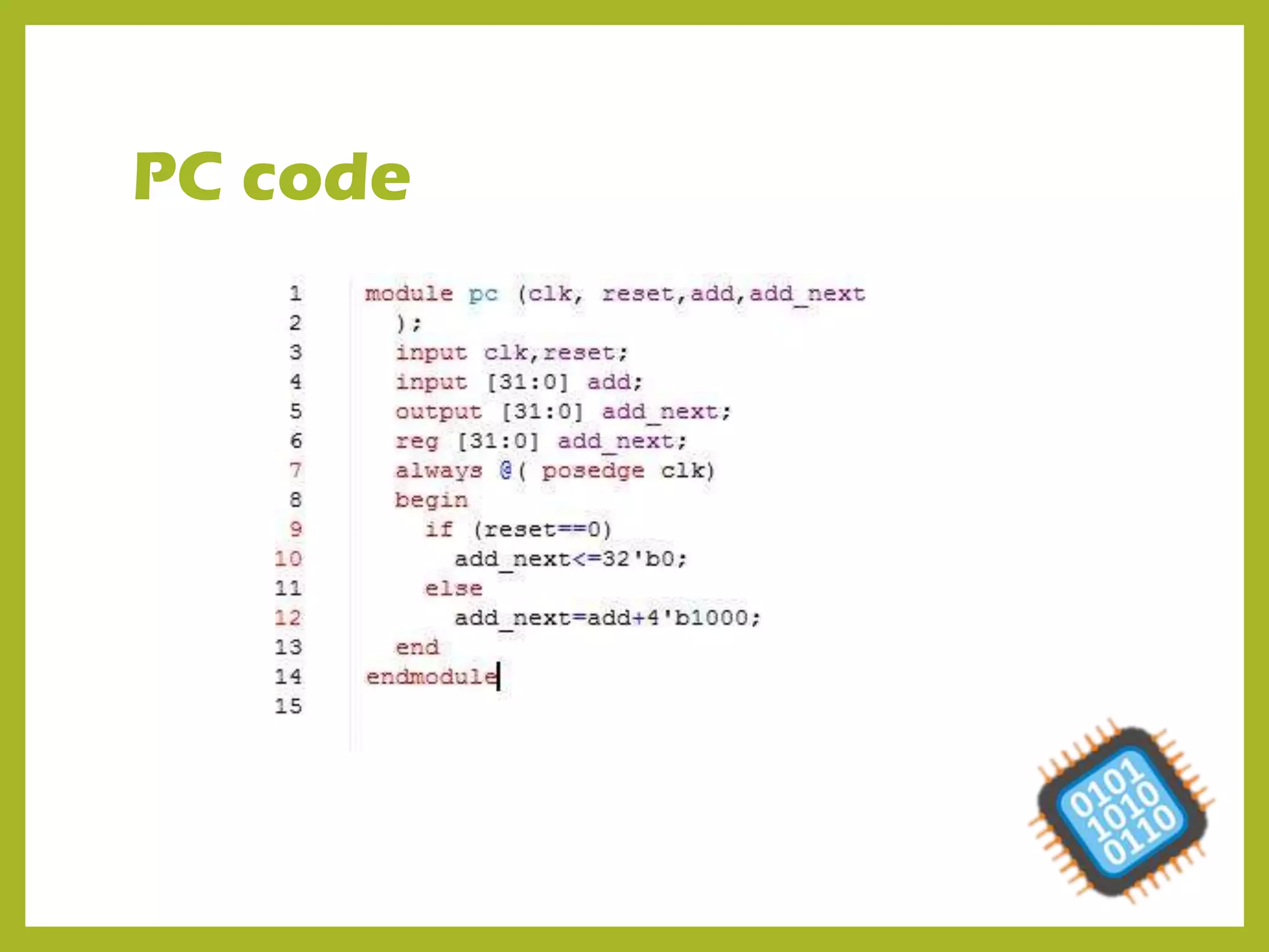
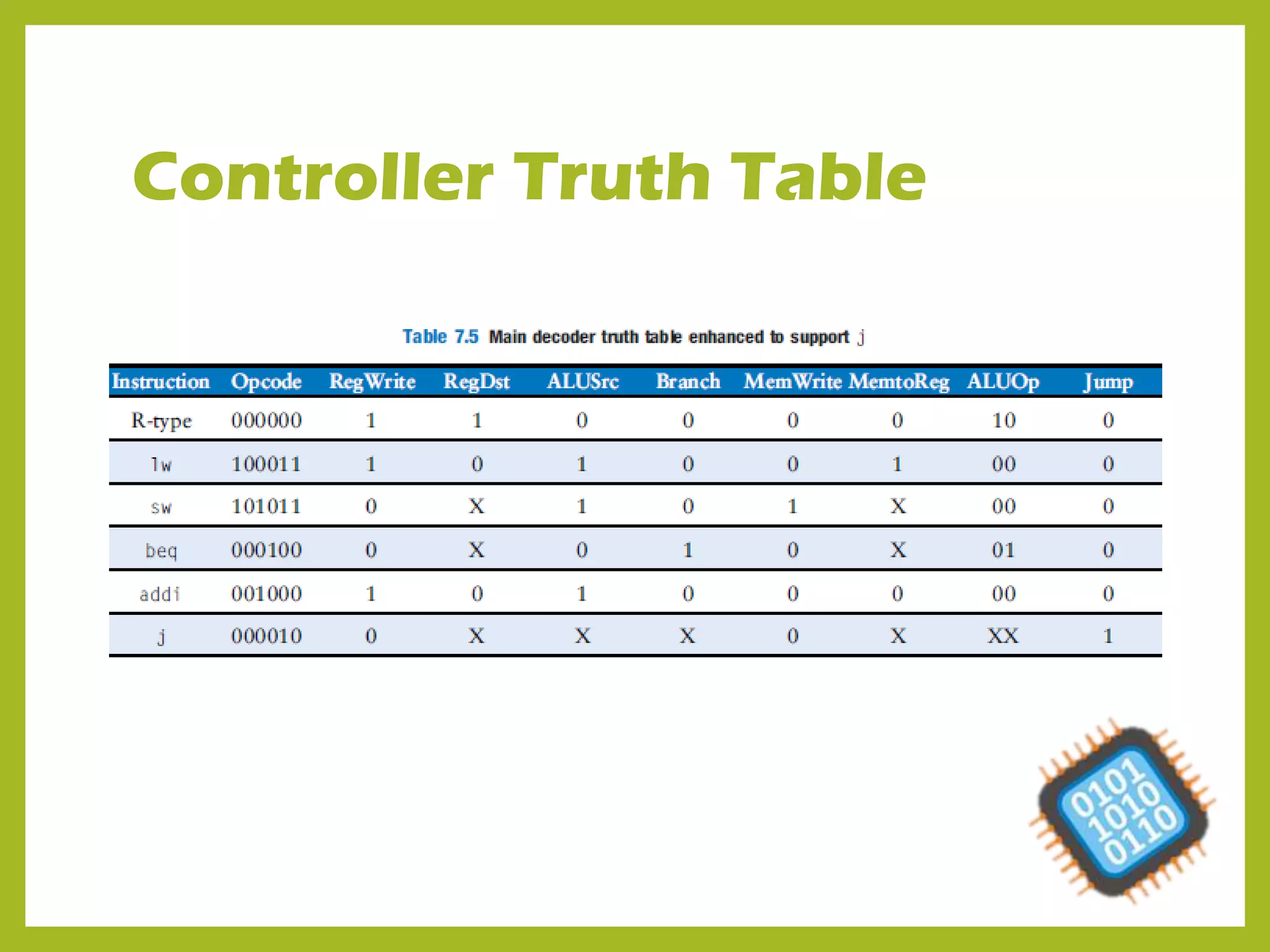
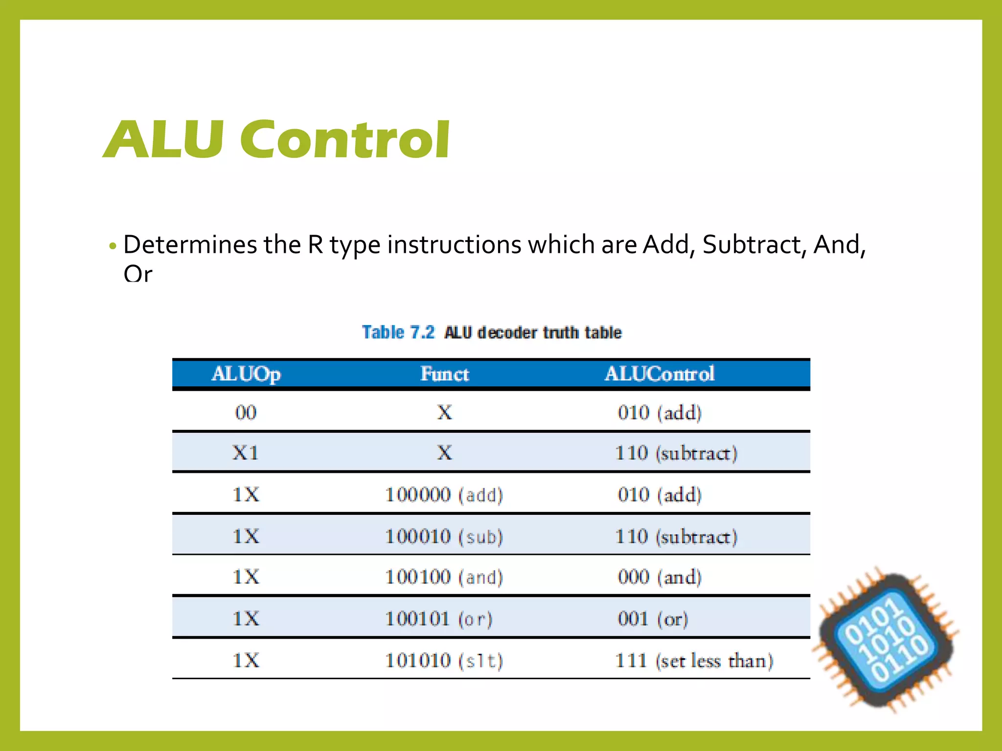
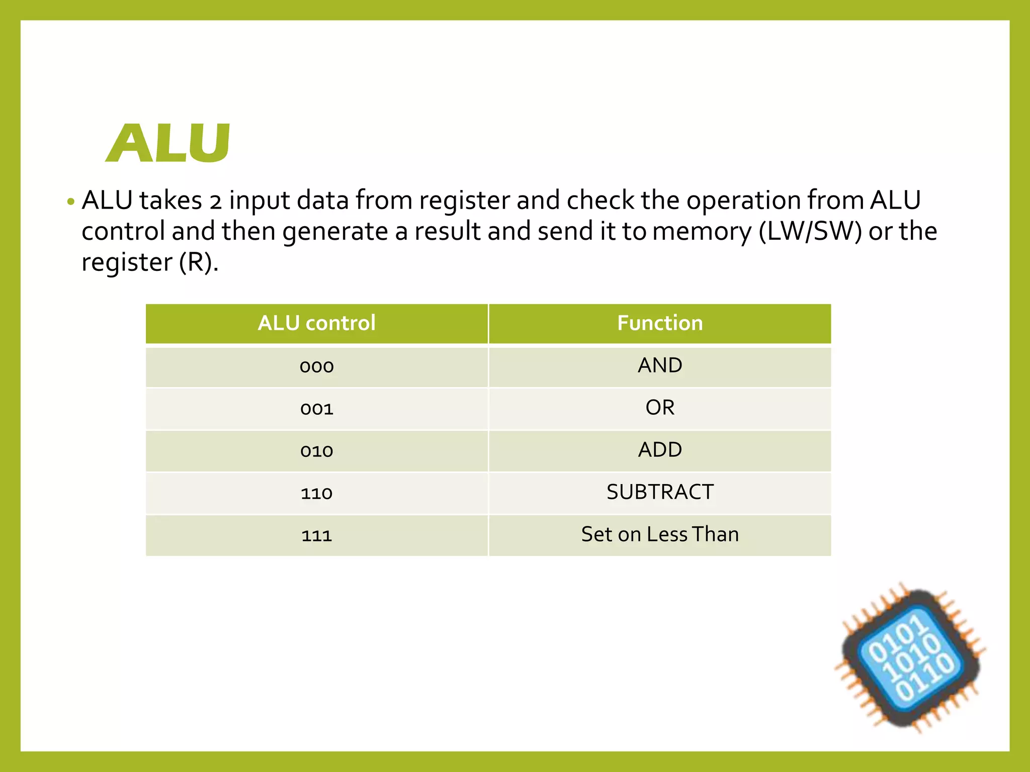
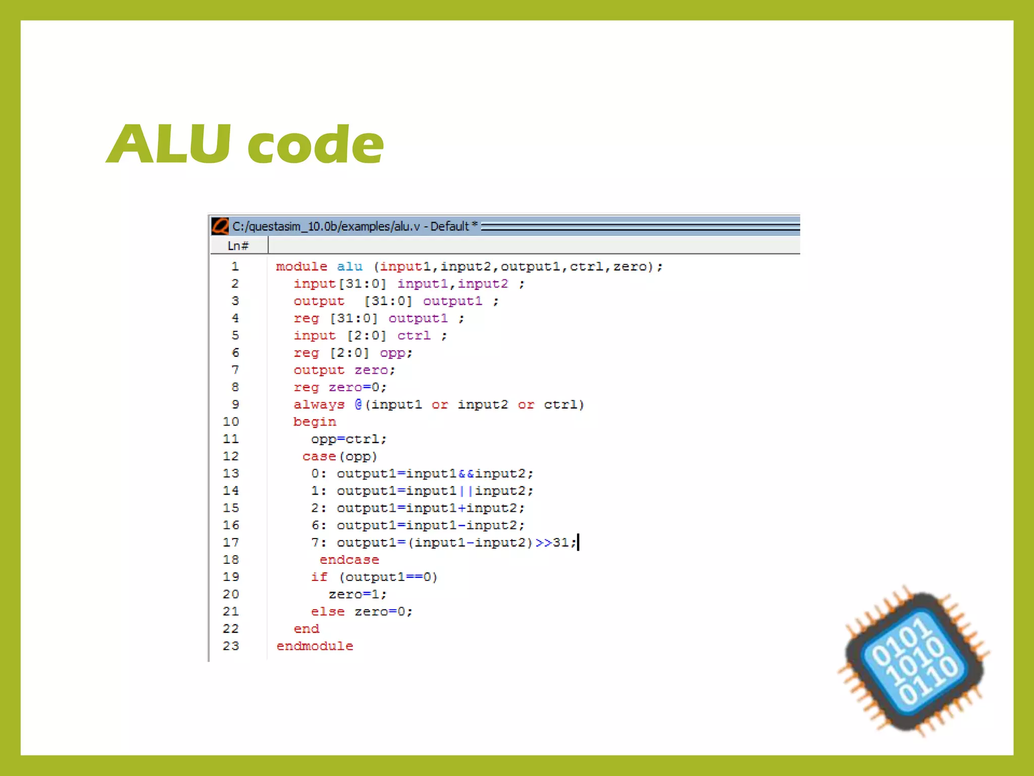
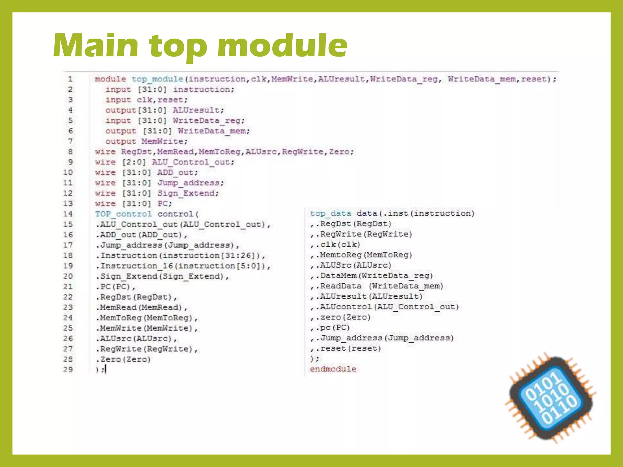
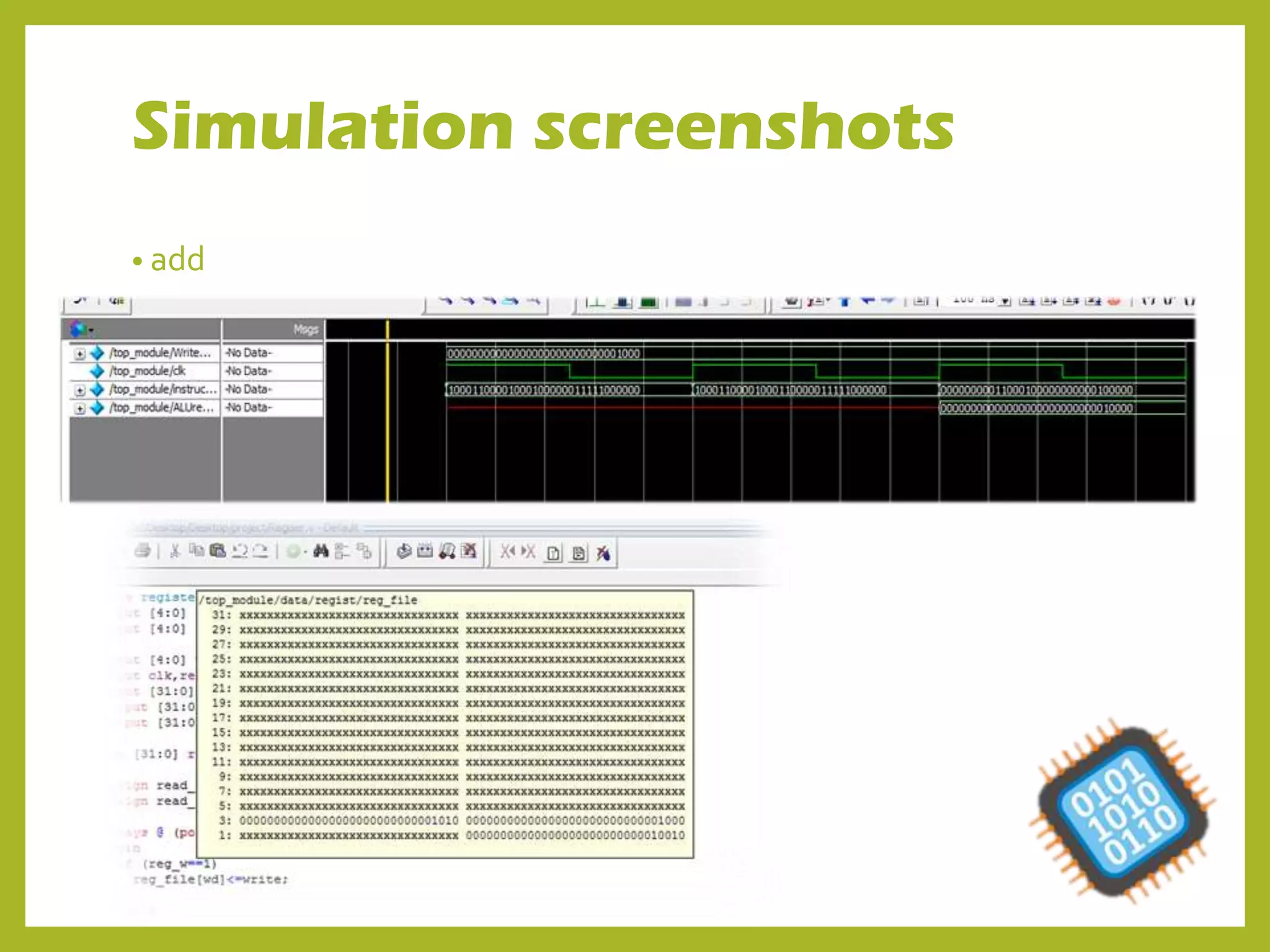
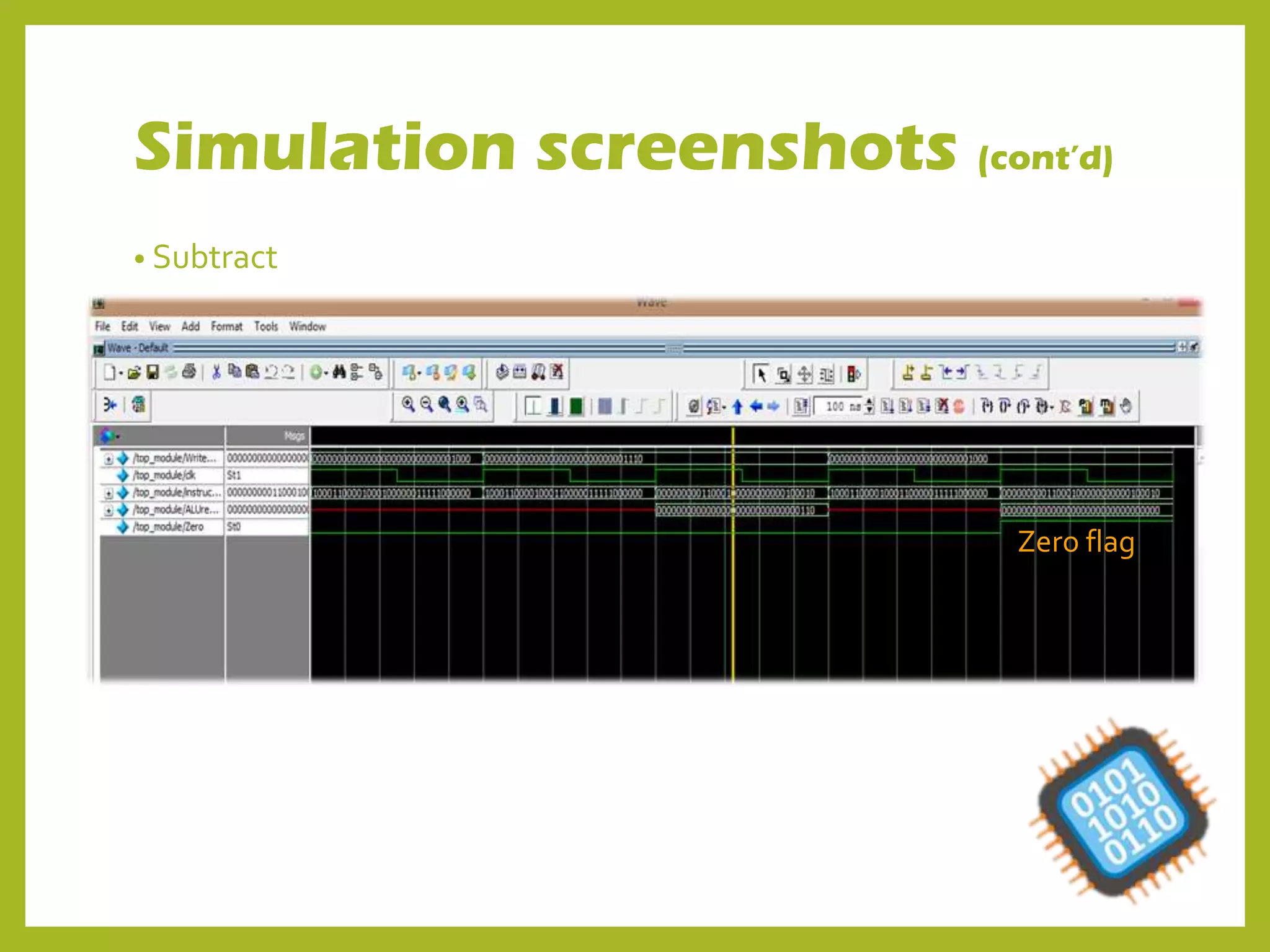
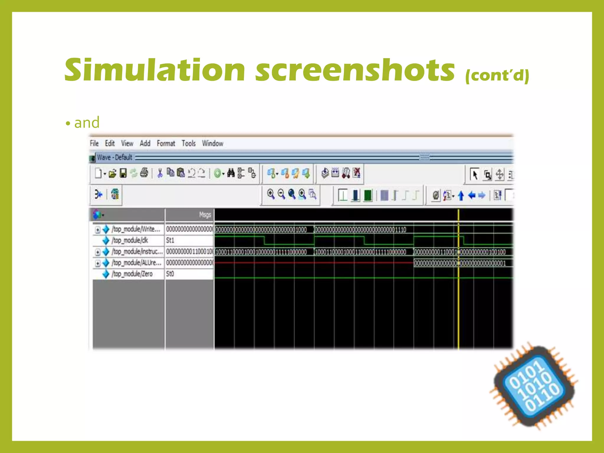
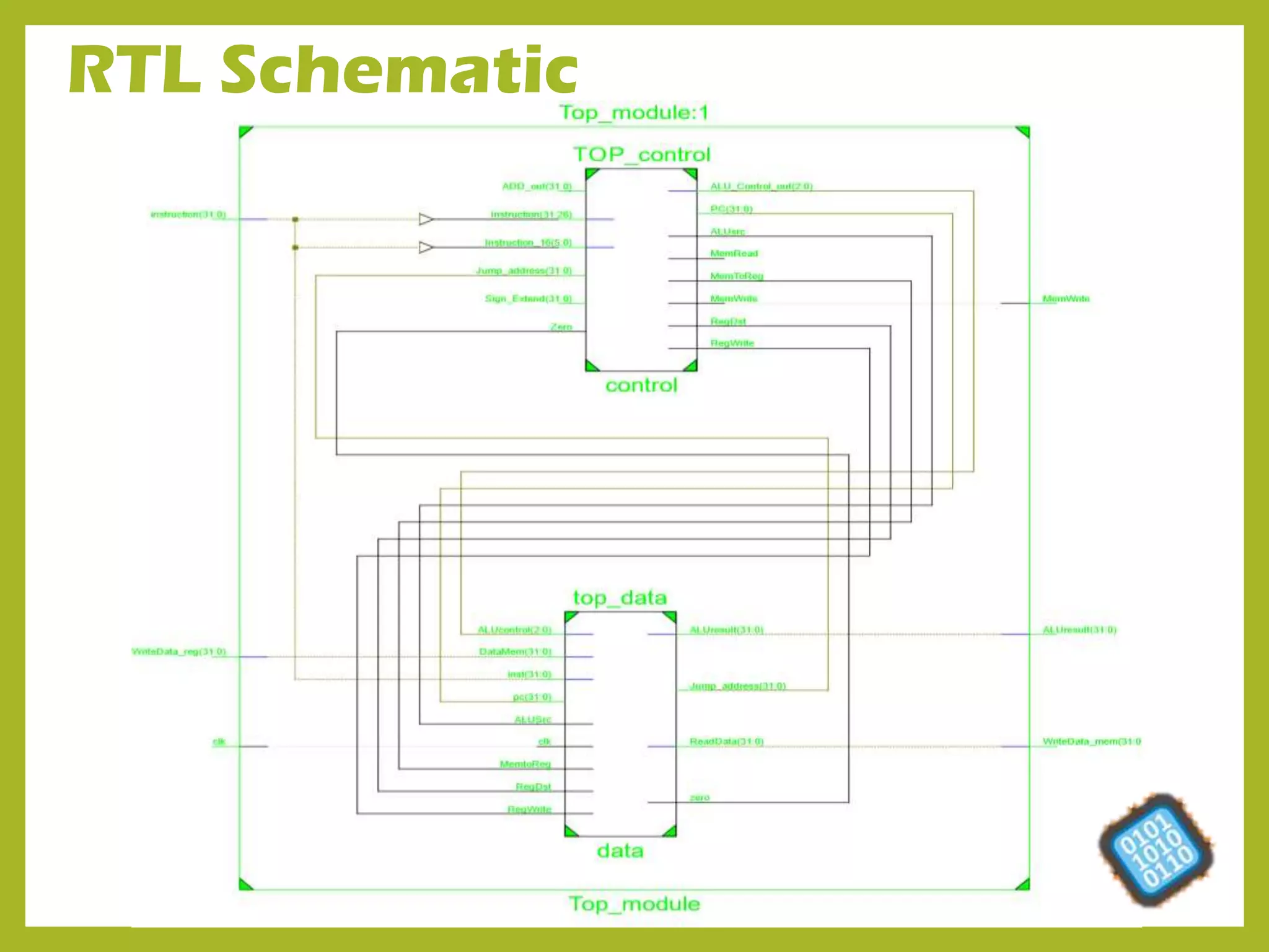
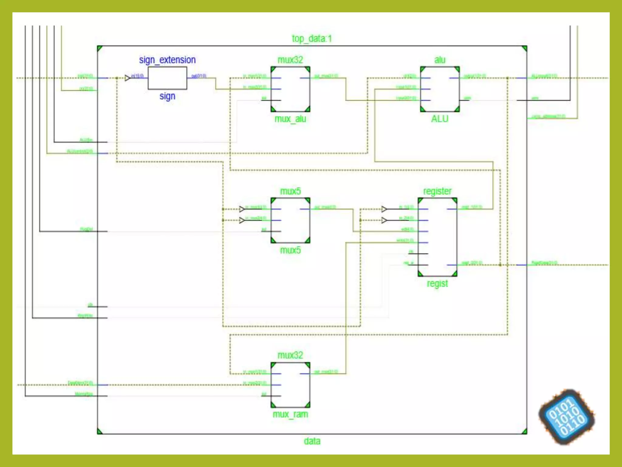
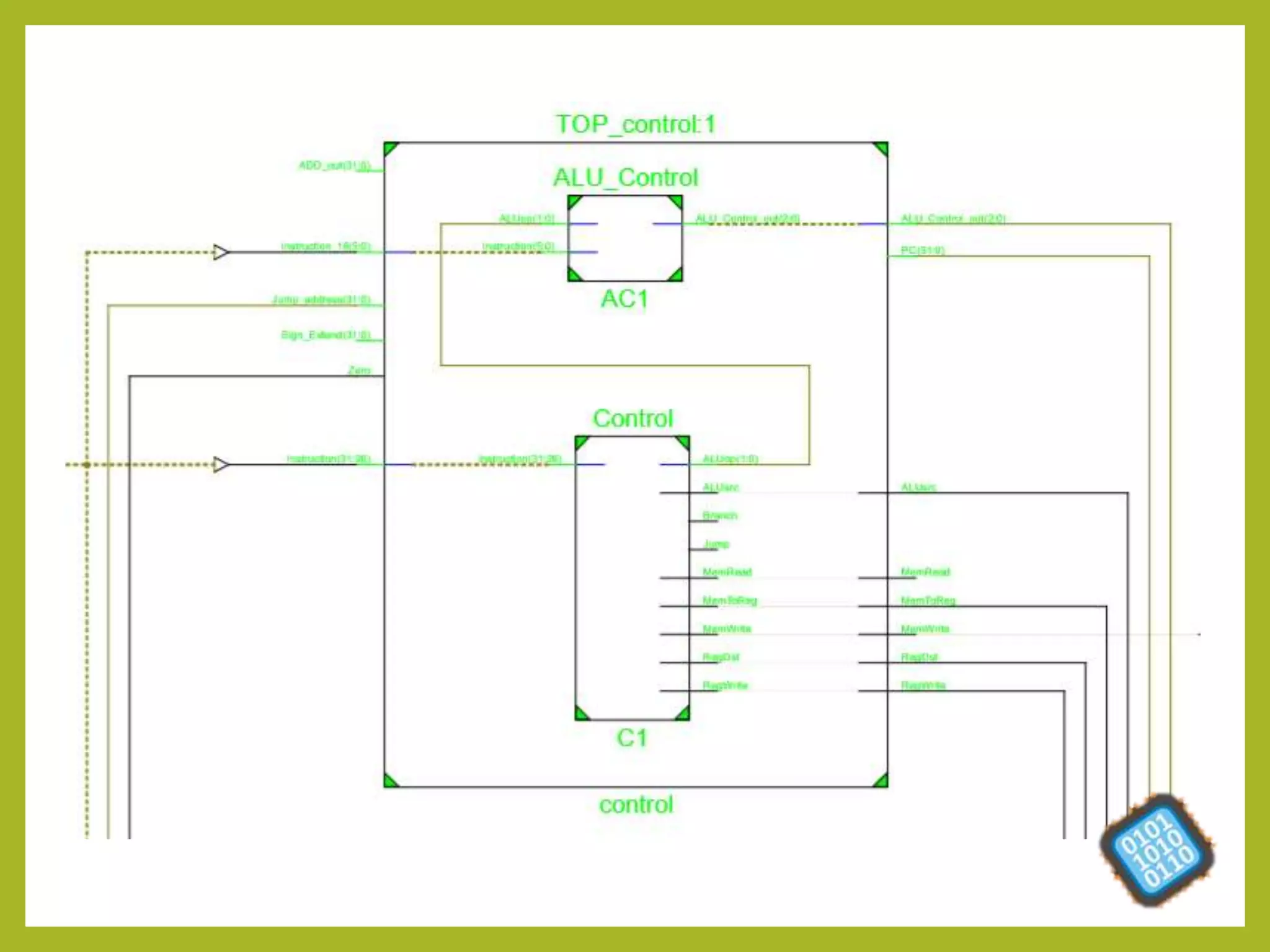
SINGLE CYCLE
PROCESSORVerilog implementation
• This processor executes each instruction in one clock cycle only.
• Compatible operations:
IType:
Load word
Store word
RType:
Add
And
Or
Subtract
SLT
JType
Beq
Register
• It takes the data addresses from instruction memory in order to
fetch the data which is already saved in it and/or write the data from
the data memory in a certain address. then save it in memory .
• Data is read through 2 32bit output ports for further operation.
• The Data required to be loaded onto the register is fed through 32
bit input port.
Register code
PC
• A program counter that compute the address of the next
instruction and pass it to the instruction memory which read that
address and pass the corresponding data to the register.
• The address of the next instruction is calculated by incrementing
the current by 4 since we deal with words (32 bit )instruction, while
the memory is byte addressable.
PC code
Controller
• It force some values for every instruction to control ALU and make
operations on data.
• It is divided into two modules:
 controller which detects R , I and J types and sends signals accordingly
ALU control which determines which R type instruction received
Controller code
Determines I type instructions Load word, Store word, Branch equal
and Jump instructions and gives outputs
The R type is determined and gives ALUop as an output which is not
00 or 01
Outputs from Controller: RegDst, Jump, Branch, MemRead,
MemToReg, MemWrite, ALUsrc, RegWrite and ALUop
Controller Truth Table
ALU Control
• Determines the R type instructions which areAdd, Subtract, And,
Or
ALU
• ALU takes 2 input data from register and check the operation from ALU
control and then generate a result and send it to memory (LW/SW) or the
register (R).
ALU control Function
000 AND
001 OR
010 ADD
110 SUBTRACT
111 Set on Less Than
ALU code
Memory
• Memory receives data address from ALU to save data in it then it
waits for an input to write data or read data.
• If read it will write data on register.
Memory code
Generic modules
Mux 32bit
Mux 5 bit
Adder
Shift left by 2
Sign extension
And gate
Data top module
Main top module
Simulation screenshots
• add
• Subtract
Zero flag
Simulation screenshots (cont’d)
• and
• Or
Simulation screenshots (cont’d)
• Slt true
Simulation screenshots (cont’d)
• Slt false
Simulation screenshots (cont’d)
RTL Schematic
Presentation computer architechure (1)

Presentation computer architechure (1)