1) The document presents a proposed efficient fixed codebook search method for the G.729 speech codec.
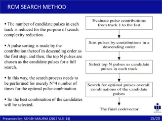
2) It combines the Iteration-Free Pulse Replacement (IFPR) search method and Reduced Candidate Mechanism (RCM) search method.
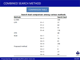
3) This combined search method requires a search load of about 7.5% of the original G.729A standard, providing greater computational efficiency.