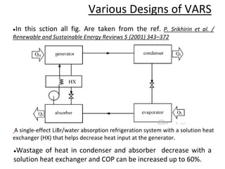
This document presents a summary of Pradeep Kumar's presentation on absorption refrigeration systems. The presentation covered the principle of operation, working fluids, experimental results using different fluids, and various designs of absorption refrigeration systems. It discussed how absorption systems use natural refrigerants like ammonia and water, have lower electricity usage than vapor compression systems, but also have lower COP. The presentation analyzed different absorption system designs including single effect, double effect, dual cycle, ejector systems, and combined cycle systems to improve performance. It provided diagrams to illustrate the various designs and discussed experimental results showing potential COP improvements over single effect systems.
![●An ejector is placed between a generator and a condenser of a
single-effect absorption system.
●LiBr/water is used as the working fluid. The ejector uses high-
pressure water vapor from the generator as the motive fluid.
A combined ejector/absorption proposed by Aphornratana and Eames [92], was
invented. High pressure refrigerant vapor from the generator enters the ejector as
motive fluid to carry the refrigerant vapor from the evaporator.](https://image.slidesharecdn.com/pptx-160512142855/85/Pptx-11-320.jpg)
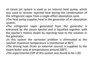
![●This cycle is a combined cycle between a steam jet heat pump and
a single-effect absorption cycle.
A combined cycle proposed by Eames and Wu [93]. The highest solution circuit
temperature is maintained at about 80°C. So the corrosion problem is alleviated.](https://image.slidesharecdn.com/pptx-160512142855/85/Pptx-13-320.jpg)


![Design and Fabrication of Vapour Absorption Refrigeration System [Libr-H20]](https://cdn.slidesharecdn.com/ss_thumbnails/c040903-1318-141004055157-conversion-gate02-thumbnail.jpg?width=640&height=640&fit=bounds)


