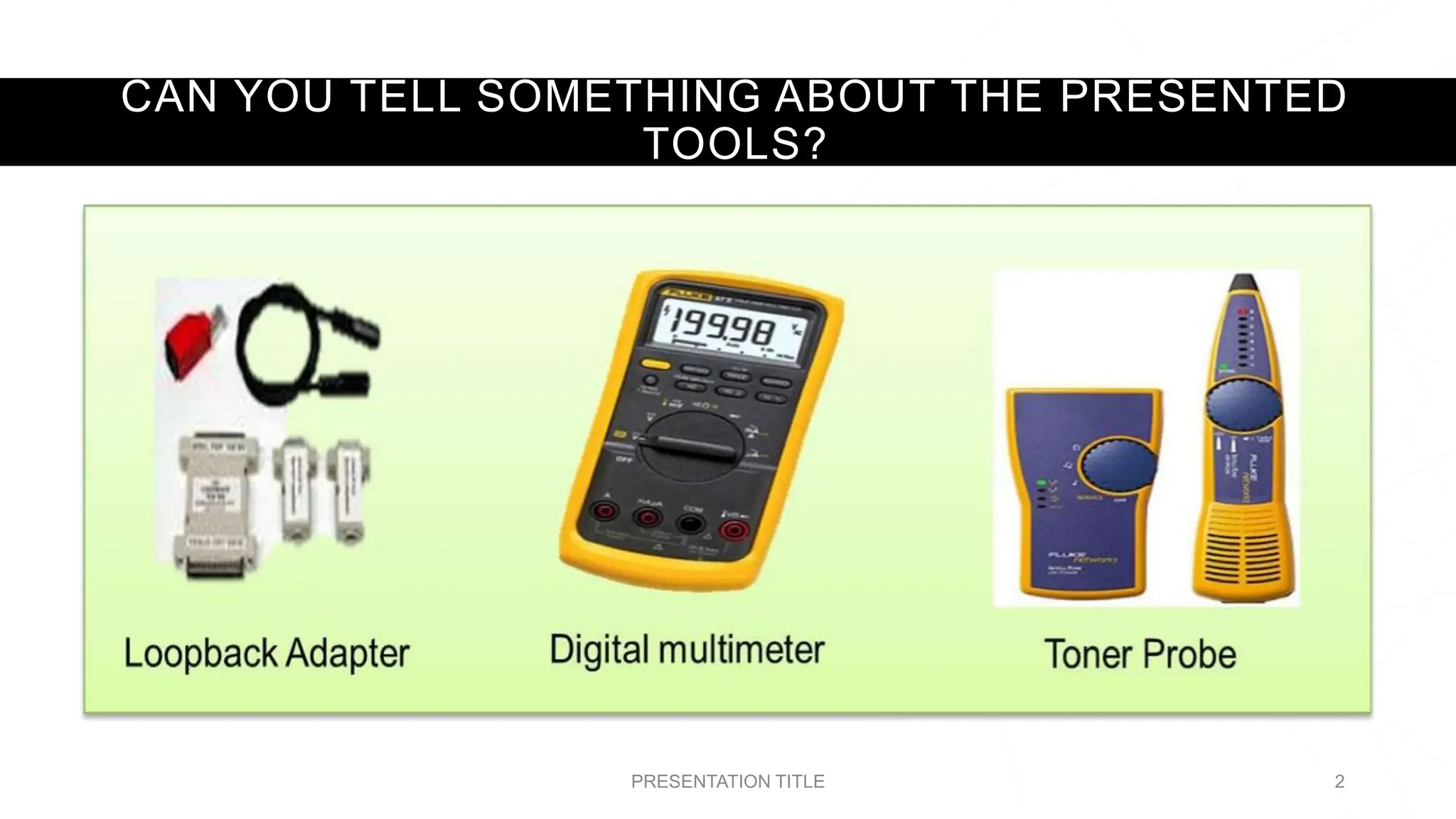
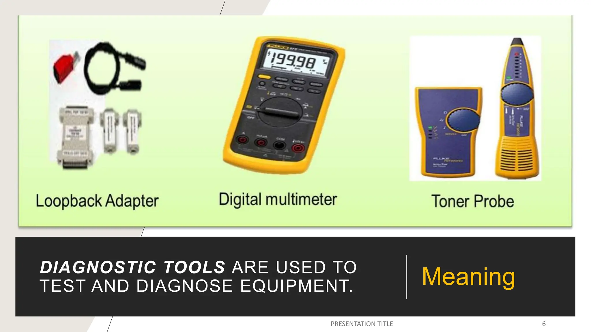
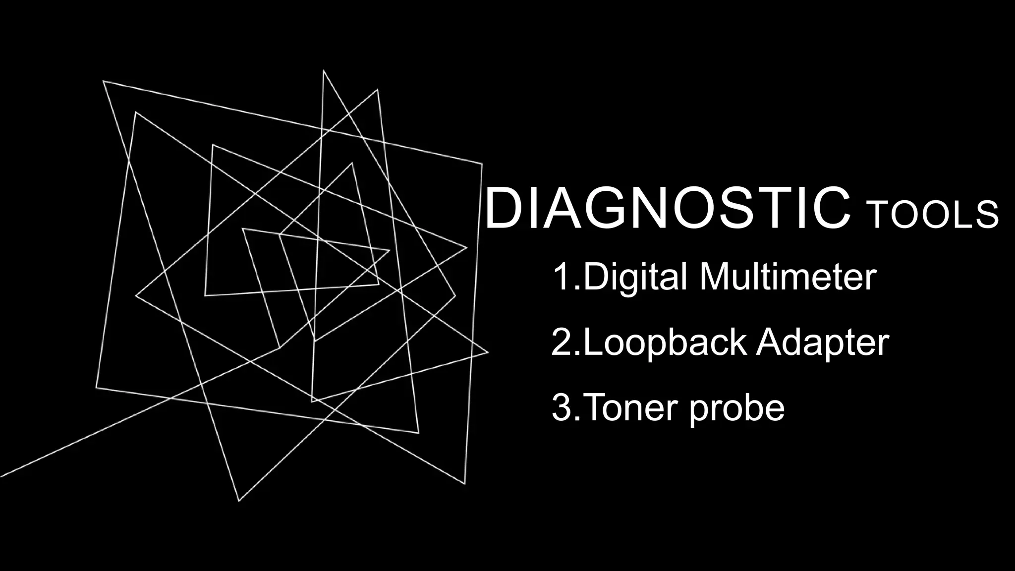
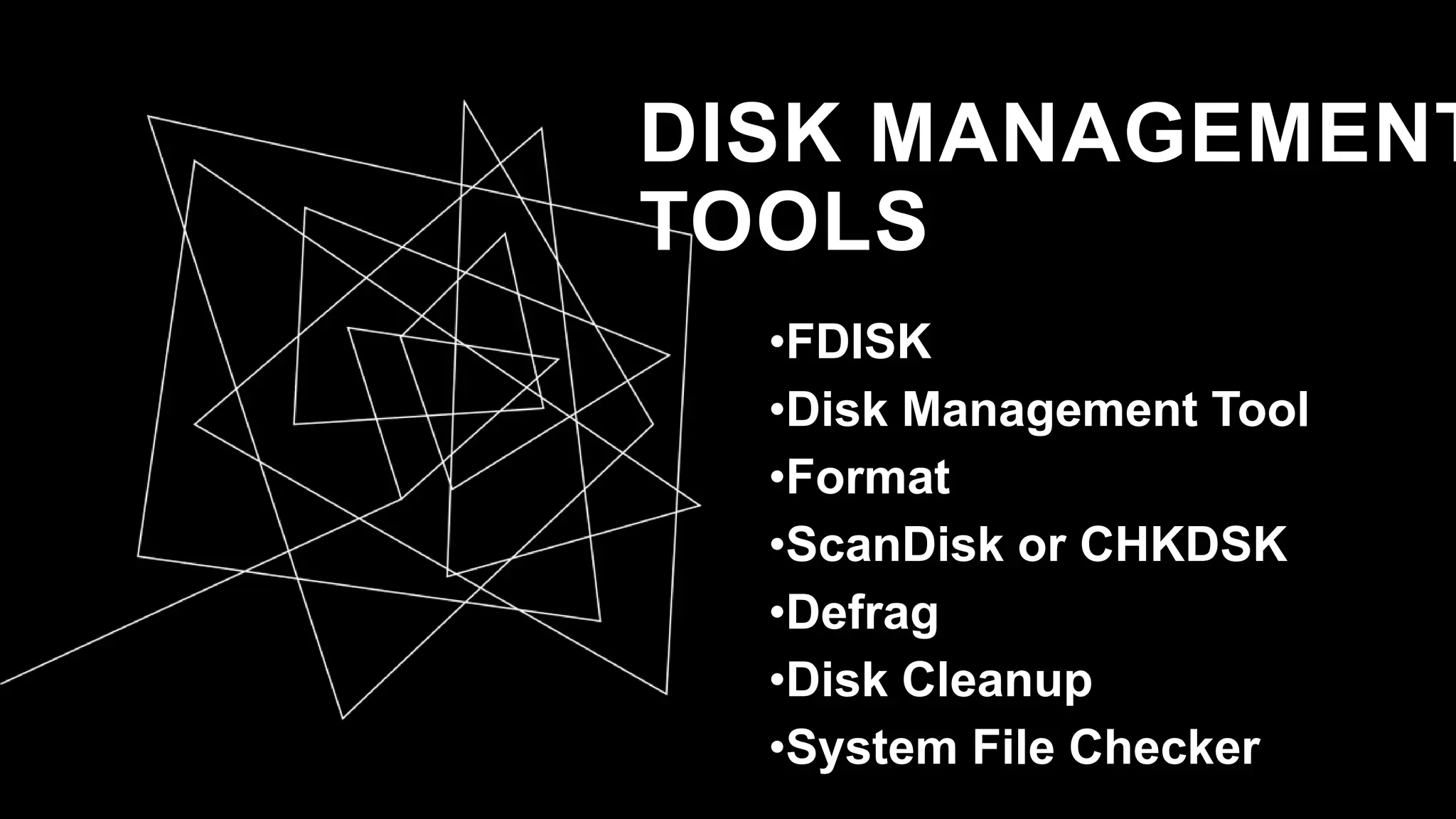
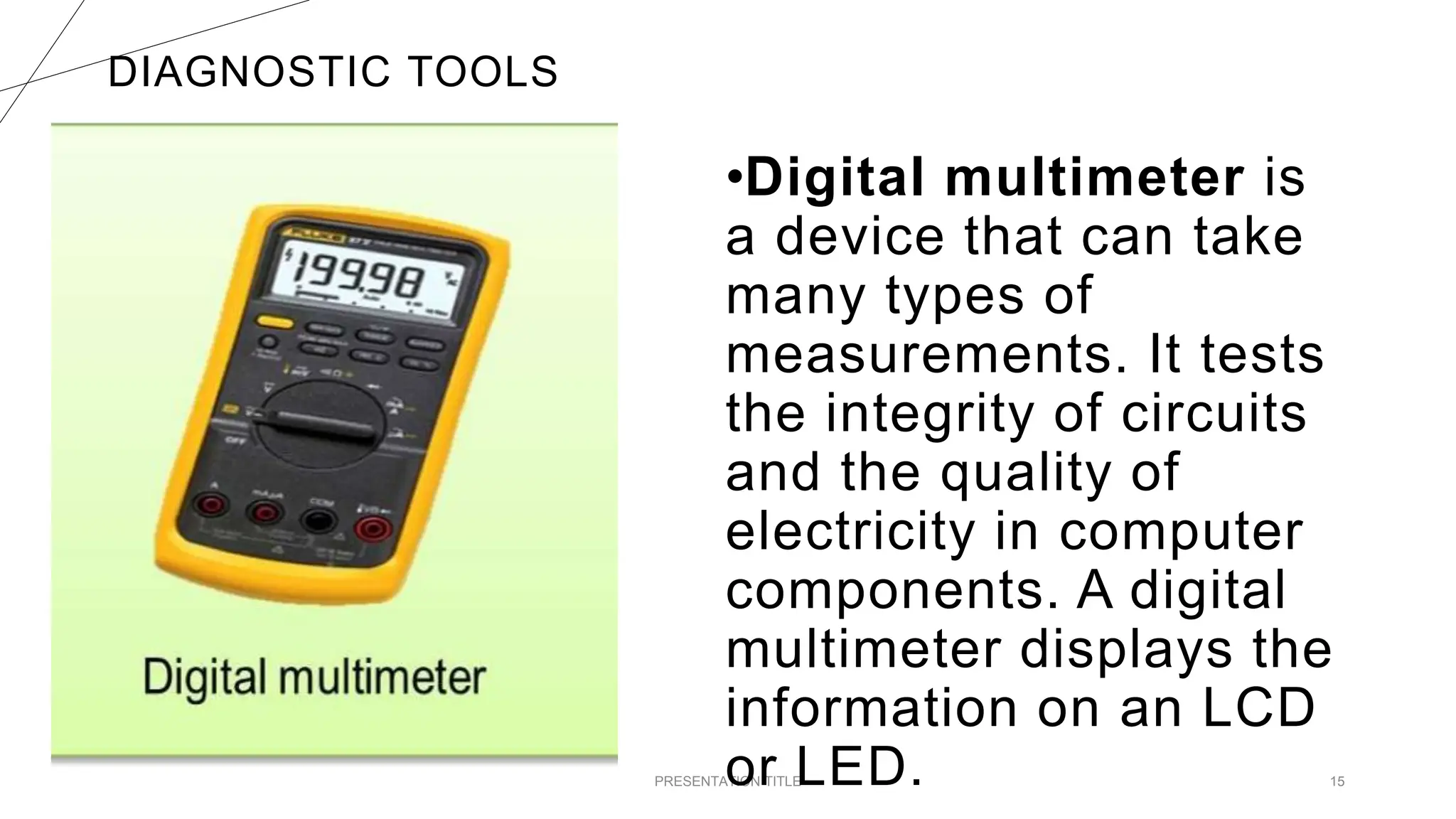
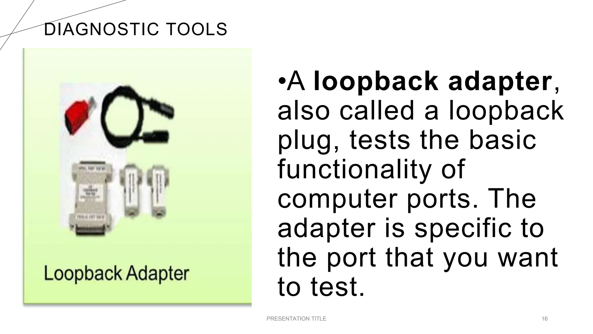
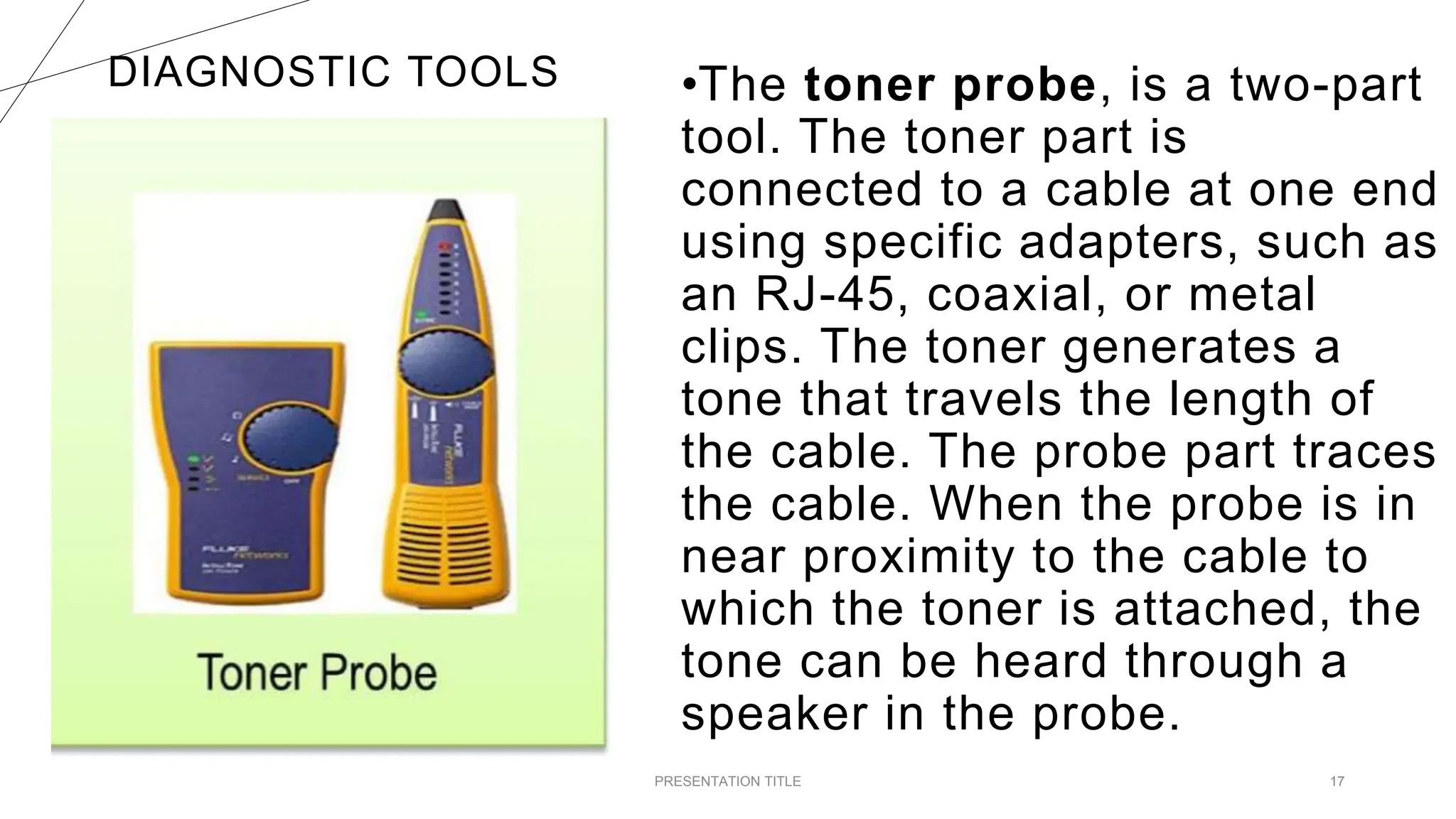
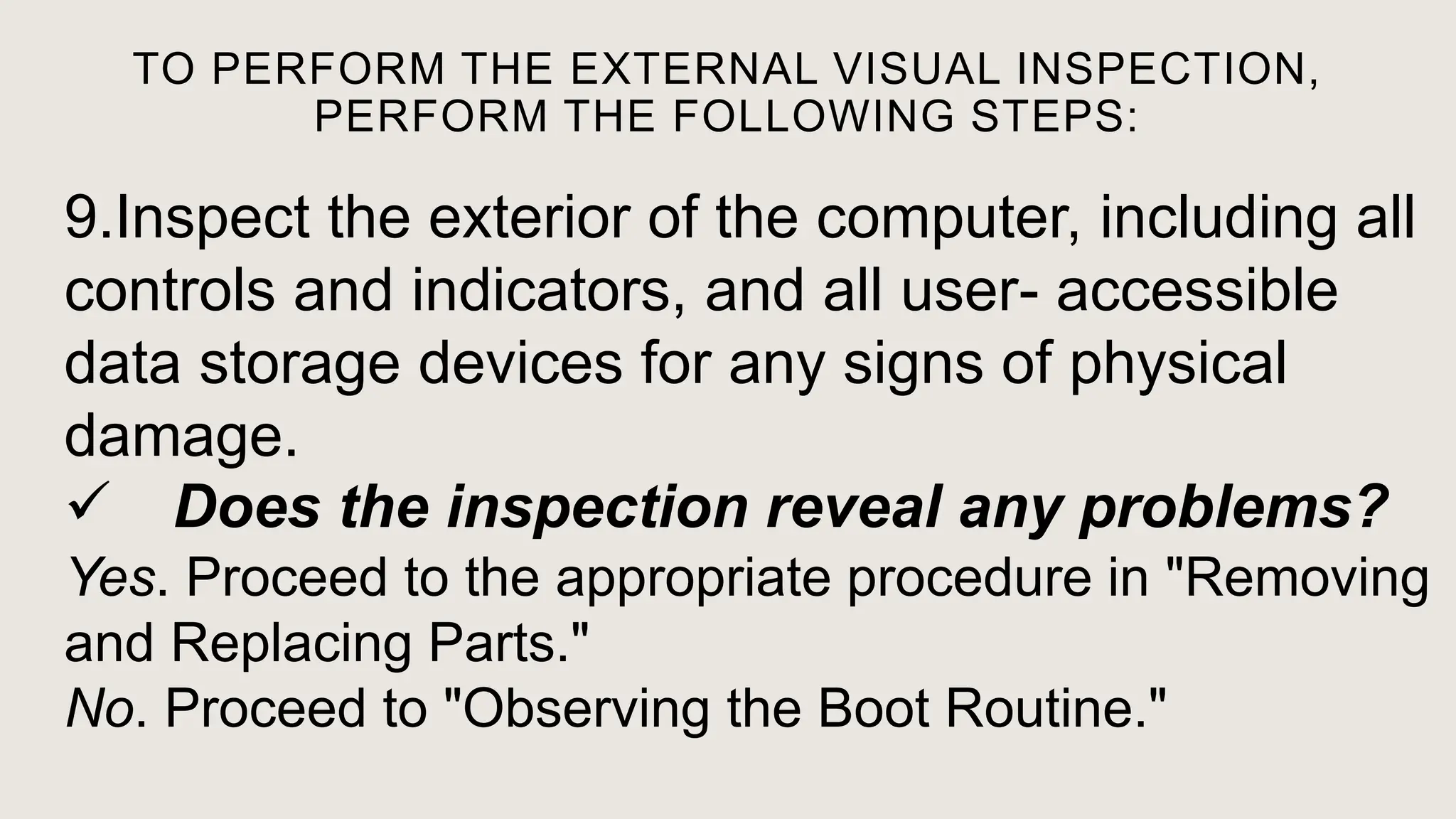
QUARTER 3
SET UP USER ACCESS IN ACCORDANCE
WITH OPERATING SYSTEM FEATURES
CAN YOU TELL SOMETHING ABOUT THE PRESENTED
TOOLS?
PRESENTATION TITLE 2
AS COMPUTER
TECHNICIANS, WHY DO
WE NEED TO
UNDERSTAND THE GOOD
PRACTICES DEMANDED
BY LAW?
3
4
TESTING INSTALLED
EQUIPMENT / DEVICES
(COMPONENTS)
THE USE OF DIAGNOSTIC
TOOLS IN TESTING INSTALLED
HARDWARE COMPONENTS AND
OTHER PERIPHERALS
5
DIAGNOSTIC TOOLS ARE USED TO
TEST AND DIAGNOSE EQUIPMENT. Meaning
DIAGNOSTIC TOOLS
1.Digital Multimeter
2.Loopback Adapter
3.Toner probe
LIKE HARDWARE TOOLS, THERE ARE A VARIETY OF
SOFTWARE TOOLS THAT CAN BE USED TO HELP
TECHNICIANS PINPOINT AND TROUBLESHOOT
PROBLEMS.
MANY OF THESE TOOLS ARE FREE AND SEVERAL
COME WITH THE WINDOWS OPERATING SYSTEM.
8
Software tools
DISK MANAGEMENT TOOLS
Software tools help diagnose computer and network
problems and determine which computer device is not
functioning correctly.
A technician must be able to use a range of software
tools to diagnose problems, maintain hardware, and
protect the data stored on a computer.
PRESENTATION TITLE 9
DISK MANAGEMENT TOOLS
You must be able to identify which
software to use in different situations.
Disk management tools help detect
and correct disk errors, prepare a disk
for data storage, and remove
unwanted files.
PRESENTATION TITLE 10
DISK MANAGEMENT
TOOLS
•FDISK
•Disk Management Tool
•Format
•ScanDisk or CHKDSK
•Defrag
•Disk Cleanup
•System File Checker
MAKE A GROUP
REPORTING
PRESENTATION TITLE 13
DIAGNOSTIC TOOLS
1.Digital Multimeter
2.Loopback Adapter
3.Toner probe
REPORTING
PRESENTATION TITLE 14
DISK MANAGEMENT
TOOLS
1. FDISK
2. Disk Management Tool
3. Format
4. ScanDisk or CHKDSK
5. Defrag
6. Disk Cleanup
7. System File Checker
DIAGNOSTIC TOOLS
PRESENTATION TITLE 15
•Digital multimeter is
a device that can take
many types of
measurements. It tests
the integrity of circuits
and the quality of
electricity in computer
components. A digital
multimeter displays the
information on an LCD
or LED.
DIAGNOSTIC TOOLS
PRESENTATION TITLE 16
•A loopback adapter,
also called a loopback
plug, tests the basic
functionality of
computer ports. The
adapter is specific to
the port that you want
to test.
DIAGNOSTIC TOOLS
PRESENTATION TITLE 17
•The toner probe, is a two-part
tool. The toner part is
connected to a cable at one end
using specific adapters, such as
an RJ-45, coaxial, or metal
clips. The toner generates a
tone that travels the length of
the cable. The probe part traces
the cable. When the probe is in
near proximity to the cable to
which the toner is attached, the
tone can be heard through a
speaker in the probe.
DISK MANAGEMENT TOOLS
18
•FDISK: A command-line tool that
creates and deletes partitions on a
hard drive. The FDISK tool is not
available in Windows XP, Vista, or 7.
It has been replaced with the Disk
Management tool
PRESENTATION TITLE 19
•Disk Management
Tool: Initializes disks,
creates partitions, and
formats partitions.
DISK MANAGEMENT TOOLS
20
•Format: Prepares a hard
drive to store information.
PRESENTATION TITLE 21
•ScanDisk or CHKDSK: Checks the
integrity of files and folders on a hard drive
by scanning the file system. These tools
might also check the disk surface for
physical errors.
DISK MANAGEMENT TOOLS
22
•Defrag: Optimizes
space on a hard drive to
allow faster access to
programs and data.
PRESENTATION TITLE 23
•Disk Cleanup: Clears space
on a hard drive by searching for
files that can be safely deleted.
DISK MANAGEMENT TOOLS
24
•System File Checker
(SFC): A command-line
tool that scans the
operating system
critical files and
replaces files that are
corrupted.
REVIEW….
WHAT IS
DIAGNOSTIC
TOOL?
t
WHAT ARE THE
THREE
DIAGNOSTIC
TOOLS?
WHAT IS DISK
MANAGEMENT?
t
WHAT ARE THE 7
DISK
MANAGEMENT
TOOLS?
ASSIGNMENT.
(NOTEBOOK)
WHY DO WE NEED TO
FAMILIARIZE THE TOOLS
PRESENTED?
t
TEST
PROCEDURE
PRESENTATION TITLE 32
A TEST PROCEDURE IS A SET OF STEPS TO
GUIDE YOU THROUGH WHAT NEEDS TO BE
DONE TO THOROUGHLY TEST THE
INSTALLATION. IT IS DESIGNED TO HELP
YOU WORK MORE EFFECTIVELY AND TO
MAKE SURE YOU TEST EVERYTHING THAT
NEEDS TESTING. TEST PROCEDURES ARE
CREATED IN-HOUSE AND COULD INCLUDE
THESE STEPS
PRESENTATION TITLE 33
GATHERING TEST INFORMATION.
THE FIRST STEP IS TO RUN THE TESTS
REQUIRED BY THE PROCEDURE AND FIND
OUT WHAT HAPPENS. YOU SHOULD
RECORD ALL THE RESULTS OF YOUR TESTS
IN A LOG SO THAT YOU KNOW WHICH PASS
AND WHICH FAIL, THEREBY REQUIRING
FURTHER ACTION.
1 PRESENTATION TITLE 34
VALIDATING THE TEST
INFORMATION.
THE NEXT STEP IS TO CHECK THE DATA
YOU GATHERED FROM THE TESTS TO
MAKE SURE IT IS CORRECT. THIS IS
USUALLY DONE BY RUNNING THE
TESTS AGAIN.
2 PRESENTATION TITLE 35
THIS STEP IS IMPORTANT BECAUSE YOU
NEED TO BE ABLE TO RECOGNIZE WHEN A
TEST SHOWS PROBLEMS OR IS
SUCCESSFUL. FOR EXAMPLE, IF PING IS
USED TO TEST A NETWORK CONNECTION
THEN ‘REQUEST TIMED OUT’ SHOWS THE
TEST WAS NOT SUCCESSFUL.
3 PRESENTATION TITLE 36
RESPONDING TO TEST
INFORMATION.
THE FINAL STEP IS AN IMPORTANT END TO
TESTING. YOU NEED TO CHECK THE
SPECIFICATION FOR THE INSTALLATION TO
MAKE SURE THAT IT HAS BEEN MET. FOR
EXAMPLE, IF A USER REQUESTED AN
UPGRADE TO MAKE THEIR DISPLAY RUN AT
1920 X 1200, THEN THE ICT PROFESSIONAL
SHOULD CHECK THAT THE GRAPHICS CARD
AND SCREEN CAN DO THIS.
4 PRESENTATION TITLE 37
CHECKING APPLICATION
EXTERNAL VISUAL
INSPECTION
PRESENTATION TITLE 38
THE EXTERNAL VISUAL INSPECTION CONSISTS
OF A QUICK INSPECTION OF THE EXTERIOR OF
THE COMPUTER, THE MONITOR, THE
KEYBOARD, ANY PERIPHERALS, AND CABLES.
WHILE PERFORMING THE VISUAL INSPECTION,
MAKE ANY NECESSARY CORRECTIONS.
39
TO PERFORM THE EXTERNAL VISUAL INSPECTION,
PERFORM THE FOLLOWING STEPS:
1. Turn off the computer, the monitor, and all
peripherals.
2. Verify that all power cables are properly
connected to the computer, the monitor and
peripherals, and their power sources.
TO PERFORM THE EXTERNAL VISUAL INSPECTION,
PERFORM THE FOLLOWING STEPS:
3. Verify that the keyboard and mouse interface
cables are firmly attached to the proper connectors
on the back of the computer.
• For a PS/2-compatible mouse, the keyboard and mouse
interface cable connectors are identical except for their labels.
•For a serial mouse, the mouse interface cable must be
firmly attached to one of the serial
port connectors, and its captive screws must be secure enough
to ensure a firm
connection.
TO PERFORM THE EXTERNAL VISUAL INSPECTION,
PERFORM THE FOLLOWING STEPS:
4.Verify that network
cables (if present) are
properly attached.
TO PERFORM THE EXTERNAL VISUAL INSPECTION,
PERFORM THE FOLLOWING STEPS:
5.Verify that any devices attached to the serial and
parallel port connectors are properly
connected. Each of the serial and parallel port
interface cables must be firmly attached to an
appropriate connector on the back of the computer
as well as to the interface connector on the device.
The captive screws that secure these connectors
at each end of the interface cable must be secure
TO PERFORM THE EXTERNAL VISUAL INSPECTION,
PERFORM THE FOLLOWING STEPS:
6. Verify that the video interface cable is
firmly attached to the video connector on
the back panel or to a video expansion
card, and also to the connector on the
back of the monitor. For proper connection
of the video monitor, see the
documentation for the monitor.
TO PERFORM THE EXTERNAL VISUAL INSPECTION,
PERFORM THE FOLLOWING STEPS:
7. Inspect all external monitor controls for any
obvious damage or improper settings. For
proper settings of the video monitor controls,
see the documentation for the monitor.
8. Inspect the keyboard to ensure that no keys
are sticking. If one or more keys are sticking, it
may be necessary to replace the keyboard.
TO PERFORM THE EXTERNAL VISUAL INSPECTION,
PERFORM THE FOLLOWING STEPS:
9.Inspect the exterior of the computer, including all
controls and indicators, and all user- accessible
data storage devices for any signs of physical
damage.
 Does the inspection reveal any problems?
Yes. Proceed to the appropriate procedure in "Removing
and Replacing Parts."
No. Proceed to "Observing the Boot Routine."
OBSERVING
THE BOOT
ROUTINE
PRESENTATION TITLE 47
AFTER YOU HAVE PERFORMED AN
EXTERNAL VISUAL INSPECTION AS
DESCRIBED IN THE PREVIOUS
SECTION, YOU SHOULD BOOT THE
SYSTEM AND, WHILE THE BOOT
ROUTINE IS RUNNING, OBSERVE THE
SYSTEM FOR ANY INDICATIONS OF
PROBLEMS. 48
 NOTE : MOST OF THE STEPS IN THIS
PROCEDURE REQUIRE OBSERVATION
OF SYSTEM FUNCTIONS AND
INDICATIONS, SOME OF WHICH CAN
OCCUR SIMULTANEOUSLY. IT MAY BE
NECESSARY TO REBOOT THE SYSTEM
SEVERAL TIMES TO COMPLETE ALL OF
THESE STEPS. 49
TO OBSERVE PROBLEM INDICATIONS DURING THE BOOT ROUTINE, PERFORM
THE FOLLOWING STEPS:
1. If the system is off, turn on all
peripherals and the computer.
2. Check the power supply fan. Does
the fan run normally?
Yes. Proceed to step 3.
No. Troubleshoot the system power supply.
TO OBSERVE PROBLEM INDICATIONS DURING THE BOOT ROUTINE, PERFORM
THE FOLLOWING STEPS:
3. Watch the <Num Lock>, <Caps Lock>, and
<Scroll Lock> indicators on the upper-right corner
of the keyboard. After all three indicators flash
momentarily, and following a long pause
(approximately 30 seconds), the Num Lock
indicator should light up and remain on (unless the
Num Lock option is set to Off in the System Setup
program).
TO OBSERVE PROBLEM INDICATIONS DURING THE BOOT ROUTINE, PERFORM
THE FOLLOWING STEPS:
 Do these indicators flash on and off within
approximately 10 seconds after the boot
routine starts?
Yes. Proceed to step 4.
No. Troubleshoot the system power supply. If the
troubleshooting procedure indicates that the
system power supply is operational, troubleshoot
the memory.
TO OBSERVE PROBLEM INDICATIONS DURING THE BOOT ROUTINE, PERFORM
THE FOLLOWING STEPS:
4. During the boot routine, observe the
system for any of the following indications:
Beep codes — A beep code is a series of
beeps that indicates an error condition.
System error messages — these
messages can indicate problems or
provide status information.
TO OBSERVE PROBLEM INDICATIONS DURING THE BOOT ROUTINE, PERFORM
THE FOLLOWING STEPS:
Diskette-drive and hard-disk drive access
indicators — These indicators light up in
response to data being transferred to or from
the drives. If either of these indicators fails to
light up during the boot routine, troubleshoot
the diskette drive or hard-disk drive
subsystem, as appropriate.
TO OBSERVE PROBLEM INDICATIONS DURING THE BOOT ROUTINE, PERFORM
THE FOLLOWING STEPS:
5. Observe the monitor screen
for the Diagnostics menu.
INTERNAL
VISUAL
INSPECTION
PRESENTATION TITLE 56
NOTICE: Before you proceed with
the internal visual inspection
described in this section, ensure
that the user has saved all open
files and exited all open application
programs if possible.
A simple visual inspection of a computer’s
interior hardware can often lead to the
source of a problem, such as a loose
expansion card, cable connector, or
mounting screw. To perform the internal
visual inspection, perform the following
steps:
1. Turn off the system, including any
attached peripherals, and disconnect all the
AC power cables from electrical outlets.
CAUTION: Before beginning to work inside
the computer, disconnect the power supply
from the power source and the power
supply cables from the power supply.
2. Remove the computer’s right
side cover.
 CAUTION: The heat sink assembly can get
extremely hot during system operations. Be sure
that it has had sufficient time to cool before
touching it.
 CAUTION: When handling the heat sink
assembly, take care to avoid sharp edges on the
heat sink.
3. Verify that the chips, expansion
cards, and SEC cartridge and heat
sink assembly or assemblies are
fully seated in their sockets or
connectors.
4. To ensure that the chips are
fully seated in their sockets,
press firmly on the top of each
chip.
5. Verify that all jumpers
are set correctly.
6. Check all cable
connectors inside the
computer to verify that they
are firmly attached to their
appropriate connectors.
7. Reinstall the computer
cover.
8. Reconnect the
computer and any
attached peripherals to
their power sources, and
turn them on.
EVALUATION
PRESENTATION TITLE 67
I. DIRECTIONS: IDENTIFY WHAT IS BEING ASKED. CHOOSE YOUR ANSWERS INSIDE THE BOX .
68
Digital multimeter
loopback adapter
Disk Management Tool
Software tools
Windows 7 boot disk
System File Checker (SFC)
test procedure
Disk Clean up
Beep codes
Defrag
Format
System error messages
_______ 1. These messages can indicate
problems or provide status information.
PRESENTATION TITLE 69
I-True or False :Directions: Write
TRUE if the statement is correct and
FALSE otherwise.
1.Before you proceed with
the internal visual
inspection, it is ok that the
user has not saved all open
files and exited all open
application programs.
PRESENTATION TITLE 70
2. Scan Disk clears
space on a hard drive
by searching for files
that can be safely
deleted.
PRESENTATION TITLE 71
2. Scan Disk clears
space on a hard drive
by searching for files
that can be safely
deleted.
PRESENTATION TITLE 72
3. As computer technician you will need a
good understanding of the health and
safety regulations from later on in your
career, so that you understand the good
practices demanded by law.
PRESENTATION TITLE 73
4. Software tools help
detect and correct disk
errors, prepare a disk for
data storage, and remove
unwanted files.
PRESENTATION TITLE 74
5. When the probe is in near
proximity to the cable to which
the toner is attached, the tone
can be heard through a
speaker in the probe.
PRESENTATION TITLE 75
6. The FDISK tool is available
in Windows XP, Vista, or 7.
PRESENTATION TITLE 76
7. Disk Management Tool is
designed to help you work
more effectively and to make
sure you test everything that
needs testing.
PRESENTATION TITLE 77
8. The final step is an
important end to testing. You
do not need to check the
specification for the installation
to make sure that it has been
met. PRESENTATION TITLE 78
9. Before beginning to work
inside the computer, connect
the power supply from the
power source and the power
supply cables from the power
supply. PRESENTATION TITLE 79
10. A digital multimeter
displays the information on an
LCD or LED.
PRESENTATION TITLE 80
PRESENTATION TITLE 81
II-Identification: Directions:
Arrange and label from 1-5 the
steps in observing problem
indications during the boot routine.
__________1. Check the power supply fan. Does the fan run normally?
__________2. Observe the monitor screen for the Diagnostics menu.
__________3. During the boot routine, observe the system for any
of the following indications: beep codes, system error
messages and diskette-drive and hard-disk drive access
indicators.
__________4. If the system is off, turn on all peripherals and the
computer.
__________5. Watch the <Num Lock>, <Caps Lock>, and <Scroll Lock>
indicators on the upper-
right corner of the keyboard.
PRESENTATION TITLE 82
PRESENTATION TITLE 83

PPT - CSS Q3- MODULE 1 handtools, esd tools, cleaning tools diagnostic tools

  • 1.
    QUARTER 3 SET UPUSER ACCESS IN ACCORDANCE WITH OPERATING SYSTEM FEATURES
  • 2.
    CAN YOU TELLSOMETHING ABOUT THE PRESENTED TOOLS? PRESENTATION TITLE 2
  • 3.
    AS COMPUTER TECHNICIANS, WHYDO WE NEED TO UNDERSTAND THE GOOD PRACTICES DEMANDED BY LAW? 3
  • 4.
    4 TESTING INSTALLED EQUIPMENT /DEVICES (COMPONENTS)
  • 5.
    THE USE OFDIAGNOSTIC TOOLS IN TESTING INSTALLED HARDWARE COMPONENTS AND OTHER PERIPHERALS 5
  • 6.
    DIAGNOSTIC TOOLS AREUSED TO TEST AND DIAGNOSE EQUIPMENT. Meaning
  • 7.
  • 8.
    LIKE HARDWARE TOOLS,THERE ARE A VARIETY OF SOFTWARE TOOLS THAT CAN BE USED TO HELP TECHNICIANS PINPOINT AND TROUBLESHOOT PROBLEMS. MANY OF THESE TOOLS ARE FREE AND SEVERAL COME WITH THE WINDOWS OPERATING SYSTEM. 8 Software tools
  • 9.
    DISK MANAGEMENT TOOLS Softwaretools help diagnose computer and network problems and determine which computer device is not functioning correctly. A technician must be able to use a range of software tools to diagnose problems, maintain hardware, and protect the data stored on a computer. PRESENTATION TITLE 9
  • 10.
    DISK MANAGEMENT TOOLS Youmust be able to identify which software to use in different situations. Disk management tools help detect and correct disk errors, prepare a disk for data storage, and remove unwanted files. PRESENTATION TITLE 10
  • 11.
    DISK MANAGEMENT TOOLS •FDISK •Disk ManagementTool •Format •ScanDisk or CHKDSK •Defrag •Disk Cleanup •System File Checker
  • 12.
  • 13.
    REPORTING PRESENTATION TITLE 13 DIAGNOSTICTOOLS 1.Digital Multimeter 2.Loopback Adapter 3.Toner probe
  • 14.
    REPORTING PRESENTATION TITLE 14 DISKMANAGEMENT TOOLS 1. FDISK 2. Disk Management Tool 3. Format 4. ScanDisk or CHKDSK 5. Defrag 6. Disk Cleanup 7. System File Checker
  • 15.
    DIAGNOSTIC TOOLS PRESENTATION TITLE15 •Digital multimeter is a device that can take many types of measurements. It tests the integrity of circuits and the quality of electricity in computer components. A digital multimeter displays the information on an LCD or LED.
  • 16.
    DIAGNOSTIC TOOLS PRESENTATION TITLE16 •A loopback adapter, also called a loopback plug, tests the basic functionality of computer ports. The adapter is specific to the port that you want to test.
  • 17.
    DIAGNOSTIC TOOLS PRESENTATION TITLE17 •The toner probe, is a two-part tool. The toner part is connected to a cable at one end using specific adapters, such as an RJ-45, coaxial, or metal clips. The toner generates a tone that travels the length of the cable. The probe part traces the cable. When the probe is in near proximity to the cable to which the toner is attached, the tone can be heard through a speaker in the probe.
  • 18.
    DISK MANAGEMENT TOOLS 18 •FDISK:A command-line tool that creates and deletes partitions on a hard drive. The FDISK tool is not available in Windows XP, Vista, or 7. It has been replaced with the Disk Management tool
  • 19.
    PRESENTATION TITLE 19 •DiskManagement Tool: Initializes disks, creates partitions, and formats partitions.
  • 20.
    DISK MANAGEMENT TOOLS 20 •Format:Prepares a hard drive to store information.
  • 21.
    PRESENTATION TITLE 21 •ScanDiskor CHKDSK: Checks the integrity of files and folders on a hard drive by scanning the file system. These tools might also check the disk surface for physical errors.
  • 22.
    DISK MANAGEMENT TOOLS 22 •Defrag:Optimizes space on a hard drive to allow faster access to programs and data.
  • 23.
    PRESENTATION TITLE 23 •DiskCleanup: Clears space on a hard drive by searching for files that can be safely deleted.
  • 24.
    DISK MANAGEMENT TOOLS 24 •SystemFile Checker (SFC): A command-line tool that scans the operating system critical files and replaces files that are corrupted.
  • 25.
  • 26.
  • 27.
  • 28.
  • 29.
    WHAT ARE THE7 DISK MANAGEMENT TOOLS?
  • 30.
  • 31.
    WHY DO WENEED TO FAMILIARIZE THE TOOLS PRESENTED? t
  • 32.
  • 33.
    A TEST PROCEDUREIS A SET OF STEPS TO GUIDE YOU THROUGH WHAT NEEDS TO BE DONE TO THOROUGHLY TEST THE INSTALLATION. IT IS DESIGNED TO HELP YOU WORK MORE EFFECTIVELY AND TO MAKE SURE YOU TEST EVERYTHING THAT NEEDS TESTING. TEST PROCEDURES ARE CREATED IN-HOUSE AND COULD INCLUDE THESE STEPS PRESENTATION TITLE 33
  • 34.
    GATHERING TEST INFORMATION. THEFIRST STEP IS TO RUN THE TESTS REQUIRED BY THE PROCEDURE AND FIND OUT WHAT HAPPENS. YOU SHOULD RECORD ALL THE RESULTS OF YOUR TESTS IN A LOG SO THAT YOU KNOW WHICH PASS AND WHICH FAIL, THEREBY REQUIRING FURTHER ACTION. 1 PRESENTATION TITLE 34
  • 35.
    VALIDATING THE TEST INFORMATION. THENEXT STEP IS TO CHECK THE DATA YOU GATHERED FROM THE TESTS TO MAKE SURE IT IS CORRECT. THIS IS USUALLY DONE BY RUNNING THE TESTS AGAIN. 2 PRESENTATION TITLE 35
  • 36.
    THIS STEP ISIMPORTANT BECAUSE YOU NEED TO BE ABLE TO RECOGNIZE WHEN A TEST SHOWS PROBLEMS OR IS SUCCESSFUL. FOR EXAMPLE, IF PING IS USED TO TEST A NETWORK CONNECTION THEN ‘REQUEST TIMED OUT’ SHOWS THE TEST WAS NOT SUCCESSFUL. 3 PRESENTATION TITLE 36 RESPONDING TO TEST INFORMATION.
  • 37.
    THE FINAL STEPIS AN IMPORTANT END TO TESTING. YOU NEED TO CHECK THE SPECIFICATION FOR THE INSTALLATION TO MAKE SURE THAT IT HAS BEEN MET. FOR EXAMPLE, IF A USER REQUESTED AN UPGRADE TO MAKE THEIR DISPLAY RUN AT 1920 X 1200, THEN THE ICT PROFESSIONAL SHOULD CHECK THAT THE GRAPHICS CARD AND SCREEN CAN DO THIS. 4 PRESENTATION TITLE 37 CHECKING APPLICATION
  • 38.
  • 39.
    THE EXTERNAL VISUALINSPECTION CONSISTS OF A QUICK INSPECTION OF THE EXTERIOR OF THE COMPUTER, THE MONITOR, THE KEYBOARD, ANY PERIPHERALS, AND CABLES. WHILE PERFORMING THE VISUAL INSPECTION, MAKE ANY NECESSARY CORRECTIONS. 39
  • 40.
    TO PERFORM THEEXTERNAL VISUAL INSPECTION, PERFORM THE FOLLOWING STEPS: 1. Turn off the computer, the monitor, and all peripherals. 2. Verify that all power cables are properly connected to the computer, the monitor and peripherals, and their power sources.
  • 41.
    TO PERFORM THEEXTERNAL VISUAL INSPECTION, PERFORM THE FOLLOWING STEPS: 3. Verify that the keyboard and mouse interface cables are firmly attached to the proper connectors on the back of the computer. • For a PS/2-compatible mouse, the keyboard and mouse interface cable connectors are identical except for their labels. •For a serial mouse, the mouse interface cable must be firmly attached to one of the serial port connectors, and its captive screws must be secure enough to ensure a firm connection.
  • 42.
    TO PERFORM THEEXTERNAL VISUAL INSPECTION, PERFORM THE FOLLOWING STEPS: 4.Verify that network cables (if present) are properly attached.
  • 43.
    TO PERFORM THEEXTERNAL VISUAL INSPECTION, PERFORM THE FOLLOWING STEPS: 5.Verify that any devices attached to the serial and parallel port connectors are properly connected. Each of the serial and parallel port interface cables must be firmly attached to an appropriate connector on the back of the computer as well as to the interface connector on the device. The captive screws that secure these connectors at each end of the interface cable must be secure
  • 44.
    TO PERFORM THEEXTERNAL VISUAL INSPECTION, PERFORM THE FOLLOWING STEPS: 6. Verify that the video interface cable is firmly attached to the video connector on the back panel or to a video expansion card, and also to the connector on the back of the monitor. For proper connection of the video monitor, see the documentation for the monitor.
  • 45.
    TO PERFORM THEEXTERNAL VISUAL INSPECTION, PERFORM THE FOLLOWING STEPS: 7. Inspect all external monitor controls for any obvious damage or improper settings. For proper settings of the video monitor controls, see the documentation for the monitor. 8. Inspect the keyboard to ensure that no keys are sticking. If one or more keys are sticking, it may be necessary to replace the keyboard.
  • 46.
    TO PERFORM THEEXTERNAL VISUAL INSPECTION, PERFORM THE FOLLOWING STEPS: 9.Inspect the exterior of the computer, including all controls and indicators, and all user- accessible data storage devices for any signs of physical damage.  Does the inspection reveal any problems? Yes. Proceed to the appropriate procedure in "Removing and Replacing Parts." No. Proceed to "Observing the Boot Routine."
  • 47.
  • 48.
    AFTER YOU HAVEPERFORMED AN EXTERNAL VISUAL INSPECTION AS DESCRIBED IN THE PREVIOUS SECTION, YOU SHOULD BOOT THE SYSTEM AND, WHILE THE BOOT ROUTINE IS RUNNING, OBSERVE THE SYSTEM FOR ANY INDICATIONS OF PROBLEMS. 48
  • 49.
     NOTE :MOST OF THE STEPS IN THIS PROCEDURE REQUIRE OBSERVATION OF SYSTEM FUNCTIONS AND INDICATIONS, SOME OF WHICH CAN OCCUR SIMULTANEOUSLY. IT MAY BE NECESSARY TO REBOOT THE SYSTEM SEVERAL TIMES TO COMPLETE ALL OF THESE STEPS. 49
  • 50.
    TO OBSERVE PROBLEMINDICATIONS DURING THE BOOT ROUTINE, PERFORM THE FOLLOWING STEPS: 1. If the system is off, turn on all peripherals and the computer. 2. Check the power supply fan. Does the fan run normally? Yes. Proceed to step 3. No. Troubleshoot the system power supply.
  • 51.
    TO OBSERVE PROBLEMINDICATIONS DURING THE BOOT ROUTINE, PERFORM THE FOLLOWING STEPS: 3. Watch the <Num Lock>, <Caps Lock>, and <Scroll Lock> indicators on the upper-right corner of the keyboard. After all three indicators flash momentarily, and following a long pause (approximately 30 seconds), the Num Lock indicator should light up and remain on (unless the Num Lock option is set to Off in the System Setup program).
  • 52.
    TO OBSERVE PROBLEMINDICATIONS DURING THE BOOT ROUTINE, PERFORM THE FOLLOWING STEPS:  Do these indicators flash on and off within approximately 10 seconds after the boot routine starts? Yes. Proceed to step 4. No. Troubleshoot the system power supply. If the troubleshooting procedure indicates that the system power supply is operational, troubleshoot the memory.
  • 53.
    TO OBSERVE PROBLEMINDICATIONS DURING THE BOOT ROUTINE, PERFORM THE FOLLOWING STEPS: 4. During the boot routine, observe the system for any of the following indications: Beep codes — A beep code is a series of beeps that indicates an error condition. System error messages — these messages can indicate problems or provide status information.
  • 54.
    TO OBSERVE PROBLEMINDICATIONS DURING THE BOOT ROUTINE, PERFORM THE FOLLOWING STEPS: Diskette-drive and hard-disk drive access indicators — These indicators light up in response to data being transferred to or from the drives. If either of these indicators fails to light up during the boot routine, troubleshoot the diskette drive or hard-disk drive subsystem, as appropriate.
  • 55.
    TO OBSERVE PROBLEMINDICATIONS DURING THE BOOT ROUTINE, PERFORM THE FOLLOWING STEPS: 5. Observe the monitor screen for the Diagnostics menu.
  • 56.
  • 57.
    NOTICE: Before youproceed with the internal visual inspection described in this section, ensure that the user has saved all open files and exited all open application programs if possible.
  • 58.
    A simple visualinspection of a computer’s interior hardware can often lead to the source of a problem, such as a loose expansion card, cable connector, or mounting screw. To perform the internal visual inspection, perform the following steps:
  • 59.
    1. Turn offthe system, including any attached peripherals, and disconnect all the AC power cables from electrical outlets. CAUTION: Before beginning to work inside the computer, disconnect the power supply from the power source and the power supply cables from the power supply.
  • 60.
    2. Remove thecomputer’s right side cover.  CAUTION: The heat sink assembly can get extremely hot during system operations. Be sure that it has had sufficient time to cool before touching it.  CAUTION: When handling the heat sink assembly, take care to avoid sharp edges on the heat sink.
  • 61.
    3. Verify thatthe chips, expansion cards, and SEC cartridge and heat sink assembly or assemblies are fully seated in their sockets or connectors.
  • 62.
    4. To ensurethat the chips are fully seated in their sockets, press firmly on the top of each chip.
  • 63.
    5. Verify thatall jumpers are set correctly.
  • 64.
    6. Check allcable connectors inside the computer to verify that they are firmly attached to their appropriate connectors.
  • 65.
    7. Reinstall thecomputer cover.
  • 66.
    8. Reconnect the computerand any attached peripherals to their power sources, and turn them on.
  • 67.
  • 68.
    I. DIRECTIONS: IDENTIFYWHAT IS BEING ASKED. CHOOSE YOUR ANSWERS INSIDE THE BOX . 68 Digital multimeter loopback adapter Disk Management Tool Software tools Windows 7 boot disk System File Checker (SFC) test procedure Disk Clean up Beep codes Defrag Format System error messages _______ 1. These messages can indicate problems or provide status information.
  • 69.
    PRESENTATION TITLE 69 I-Trueor False :Directions: Write TRUE if the statement is correct and FALSE otherwise.
  • 70.
    1.Before you proceedwith the internal visual inspection, it is ok that the user has not saved all open files and exited all open application programs. PRESENTATION TITLE 70
  • 71.
    2. Scan Diskclears space on a hard drive by searching for files that can be safely deleted. PRESENTATION TITLE 71
  • 72.
    2. Scan Diskclears space on a hard drive by searching for files that can be safely deleted. PRESENTATION TITLE 72
  • 73.
    3. As computertechnician you will need a good understanding of the health and safety regulations from later on in your career, so that you understand the good practices demanded by law. PRESENTATION TITLE 73
  • 74.
    4. Software toolshelp detect and correct disk errors, prepare a disk for data storage, and remove unwanted files. PRESENTATION TITLE 74
  • 75.
    5. When theprobe is in near proximity to the cable to which the toner is attached, the tone can be heard through a speaker in the probe. PRESENTATION TITLE 75
  • 76.
    6. The FDISKtool is available in Windows XP, Vista, or 7. PRESENTATION TITLE 76
  • 77.
    7. Disk ManagementTool is designed to help you work more effectively and to make sure you test everything that needs testing. PRESENTATION TITLE 77
  • 78.
    8. The finalstep is an important end to testing. You do not need to check the specification for the installation to make sure that it has been met. PRESENTATION TITLE 78
  • 79.
    9. Before beginningto work inside the computer, connect the power supply from the power source and the power supply cables from the power supply. PRESENTATION TITLE 79
  • 80.
    10. A digitalmultimeter displays the information on an LCD or LED. PRESENTATION TITLE 80
  • 81.
    PRESENTATION TITLE 81 II-Identification:Directions: Arrange and label from 1-5 the steps in observing problem indications during the boot routine.
  • 82.
    __________1. Check thepower supply fan. Does the fan run normally? __________2. Observe the monitor screen for the Diagnostics menu. __________3. During the boot routine, observe the system for any of the following indications: beep codes, system error messages and diskette-drive and hard-disk drive access indicators. __________4. If the system is off, turn on all peripherals and the computer. __________5. Watch the <Num Lock>, <Caps Lock>, and <Scroll Lock> indicators on the upper- right corner of the keyboard. PRESENTATION TITLE 82
  • 83.

Editor's Notes

  • #5 As computer technician you will need a good understanding of the health and safety regulations from early on in your career, so that you understand the good practices demanded by law. In particular, you need to:  report any accidents   take reasonable care of your own health and safety when moving heavy components   not cause any electrical hazards   make sure that workstations meet safety requirements.   You need to adhere to health and safety regulations as they will help to protect you and others and will avoid any unnecessary legal action for reckless and unsafe working practices. If you identify any health and safety problems, you should tell your line manager or the health and safety representative immediately. The most basic test is to switch the system on to check it starts without errors. ICT professionals are also likely to use tools and utilities to check that all is well with the system after an installation.
  • #8 Hardware diagnostic tools: Make a group to report on these tools.
  • #9 Make a group to report on these ter
  • #12 Hardware diagnostic tools: Make a group to report on these tools.
  • #19 Make a group to report on these ter
  • #21 Make a group to report on these ter
  • #23 Make a group to report on these ter
  • #25 Make a group to report on these ter