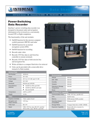
4630 North Avenue n Oceanside CA 92056 n 760.945.0230 n www.interfacedisplays.com
Data Sheet
ds_DataRec_
20550-01.pdf
Page 1 of 2
Jan-14-13
Power-Switching
Data Recorder
General Data
Part Number 20550-01
Power 50 V DC
Power Supply 28 V to 12 V DC and 5 V DC
Voltage 28 V DC
Standards DO160 and AS9100
Panel Buttons/
Switches
n On/Off for INS and CDU
n On/Off for MCSG and radar
n Record On/Off
Temperature -40°F to +85°F
Weight 4.6 lbs
Video
Graphics Controller Video capture board
Navigation and
Radar Interface
1553 bus
Video Input RS-170
Signal USB, 1553 bus data, RS-422, and On/
Off for INS, radar, MCSG, and CDU
Environmental
Altitude DO160
EMI / EMC DO160
Humidity DO160
Vibration DO160
Operating & Storage
Temperature
DO160
Shock DO160
Embedded PC Capability
Communication Ports USB, 1553 bus, and RS-422
CPU Intel® Atom
Memory 8GB internal, 8GB recorded
Operating System
Compatibility
Windows® XP
Storage Media Compact flash drive (4GB–128GB)
Expansion Capability Removable drive instead of a
flash module
Interface’s power-switching data recorder was
designed to document radar and navigation
information to be reviewed on a conveniently
located CPU at flight completion.
The functionality of the unit includes:
n On/Off function for the mission computer
symbol generator (MCSG) and radar
n On/Off function for an inertial
navigation system (INS)
n On/Off function for recording
n Records radar video
n Records 1553 bus data to and from bus
controller to remote terminals
n Records 1553 bus data to both mission bus
and navigation bus
n Writes all data to a compact flash drive for retrieval
n Units can be provided with a removable drive
instead of a flash module.
4630 North Avenue n Oceanside CA 92056 n 760.945.0230 n www.interfacedisplays.com
Pin Function Destination
J1 1 Switch 4-4 Spare
2 Switch 4-10 Spare
3 USB 5V USB to MFD
4 Data+ USB to MFD
5 Data- USB to MFD
6 GND USB to MFD
7 GND Ethernet to AC
8 1553A+ (M) 1553 Mission Bus
9 1553A- (M) 1553 Mission Bus
10 GND 1553 Mission Bus
11 1553B+ (M) 1553 Mission Bus
12 1553B- (M) 1553 Mission Bus
13 GND 1553 Navigation Bus
14 1553A+ (N) 1553 Navigation Bus
15 1553A- (N) 1553 Navigation Bus
16 GND 1553 Navigation Bus
17 1553B+ (N) 1553 Navigation Bus
18 1553B- (N) 1553 Navigation Bus
19 GND 1553 Navigation Bus
20 5 V AC Dimming from AC
21 5 V AC Dimming from AC
22 Spare
23 Spare
24 Switch 1-1 On/Off DTR, MFD
25 Switch 1-8 On/Off DTR, MFD
26 Switch 1-4 On//Off INS
27 Switch 1-10 On/Off INS
28 Switch 3-1 Data Record On
29 Switch 3-8 Data Record On
30 28 V DC Power from AC
31 28 V DC RTN Power from AC
32 Switch 2-1 On/Off Radar
33 Switch 2-8 On/Off Radar
34 Switch 2-4 On/Off MCSG
35 Switch 2-10 On/Off MCSG
36 Switch 4-1 Spare
37 Switch 4-8 Spare
38 ETX+ Ethernet to AC
39 ETX- Ethernet to AC
40 RTX+ Ethernet to AC
41 RTX- Ethernet to AC
J2 RCA 1a Video In MFD BAY2-1
RCA 1b Video RTN MFD2-2
J3 RCA 2a Video Out
RCA 2b Video Out RTN
J4 RCA 3a Spare
RCA 3b Spare
J5 RCA 4a Spare
RCA 4b Spare
ds_DataRec_
20550-01.pdf
Page 2 of 2
Jan-14-13
Data Sheet
E
Text
shown
for ref
only
Door
latch
Blank
plate
Switch guard to
be mounted on
all switches
RECORD
MCSG/
RADAR
MFD/
INS
(A)
(A)
(A)
Compact flash
door
4X DZUS
fasteners
(A)
(A) Write
indicator
lamp
1
(A)
(A)
(A)
Switch
guard
(A)
2 3
(A)
(A)
(A)
(A)
(A)
(A)
(A)
(A)
4X Amphenol
31-2225
connector
J1
J2 J3 J4 J5
J2 thru J5:
function TBD
Located approx
where shown
M83723/72R2041N
connector;
mating connector
M83723/75R2041N
FrontRightSideBack
(A) Dimensions available upon request.

Power-Switching Data Recorder Data Sheet (Interface Displays)

  • 1.
    4630 North Avenuen Oceanside CA 92056 n 760.945.0230 n www.interfacedisplays.com Data Sheet ds_DataRec_ 20550-01.pdf Page 1 of 2 Jan-14-13 Power-Switching Data Recorder General Data Part Number 20550-01 Power 50 V DC Power Supply 28 V to 12 V DC and 5 V DC Voltage 28 V DC Standards DO160 and AS9100 Panel Buttons/ Switches n On/Off for INS and CDU n On/Off for MCSG and radar n Record On/Off Temperature -40°F to +85°F Weight 4.6 lbs Video Graphics Controller Video capture board Navigation and Radar Interface 1553 bus Video Input RS-170 Signal USB, 1553 bus data, RS-422, and On/ Off for INS, radar, MCSG, and CDU Environmental Altitude DO160 EMI / EMC DO160 Humidity DO160 Vibration DO160 Operating & Storage Temperature DO160 Shock DO160 Embedded PC Capability Communication Ports USB, 1553 bus, and RS-422 CPU Intel® Atom Memory 8GB internal, 8GB recorded Operating System Compatibility Windows® XP Storage Media Compact flash drive (4GB–128GB) Expansion Capability Removable drive instead of a flash module Interface’s power-switching data recorder was designed to document radar and navigation information to be reviewed on a conveniently located CPU at flight completion. The functionality of the unit includes: n On/Off function for the mission computer symbol generator (MCSG) and radar n On/Off function for an inertial navigation system (INS) n On/Off function for recording n Records radar video n Records 1553 bus data to and from bus controller to remote terminals n Records 1553 bus data to both mission bus and navigation bus n Writes all data to a compact flash drive for retrieval n Units can be provided with a removable drive instead of a flash module.
  • 2.
    4630 North Avenuen Oceanside CA 92056 n 760.945.0230 n www.interfacedisplays.com Pin Function Destination J1 1 Switch 4-4 Spare 2 Switch 4-10 Spare 3 USB 5V USB to MFD 4 Data+ USB to MFD 5 Data- USB to MFD 6 GND USB to MFD 7 GND Ethernet to AC 8 1553A+ (M) 1553 Mission Bus 9 1553A- (M) 1553 Mission Bus 10 GND 1553 Mission Bus 11 1553B+ (M) 1553 Mission Bus 12 1553B- (M) 1553 Mission Bus 13 GND 1553 Navigation Bus 14 1553A+ (N) 1553 Navigation Bus 15 1553A- (N) 1553 Navigation Bus 16 GND 1553 Navigation Bus 17 1553B+ (N) 1553 Navigation Bus 18 1553B- (N) 1553 Navigation Bus 19 GND 1553 Navigation Bus 20 5 V AC Dimming from AC 21 5 V AC Dimming from AC 22 Spare 23 Spare 24 Switch 1-1 On/Off DTR, MFD 25 Switch 1-8 On/Off DTR, MFD 26 Switch 1-4 On//Off INS 27 Switch 1-10 On/Off INS 28 Switch 3-1 Data Record On 29 Switch 3-8 Data Record On 30 28 V DC Power from AC 31 28 V DC RTN Power from AC 32 Switch 2-1 On/Off Radar 33 Switch 2-8 On/Off Radar 34 Switch 2-4 On/Off MCSG 35 Switch 2-10 On/Off MCSG 36 Switch 4-1 Spare 37 Switch 4-8 Spare 38 ETX+ Ethernet to AC 39 ETX- Ethernet to AC 40 RTX+ Ethernet to AC 41 RTX- Ethernet to AC J2 RCA 1a Video In MFD BAY2-1 RCA 1b Video RTN MFD2-2 J3 RCA 2a Video Out RCA 2b Video Out RTN J4 RCA 3a Spare RCA 3b Spare J5 RCA 4a Spare RCA 4b Spare ds_DataRec_ 20550-01.pdf Page 2 of 2 Jan-14-13 Data Sheet E Text shown for ref only Door latch Blank plate Switch guard to be mounted on all switches RECORD MCSG/ RADAR MFD/ INS (A) (A) (A) Compact flash door 4X DZUS fasteners (A) (A) Write indicator lamp 1 (A) (A) (A) Switch guard (A) 2 3 (A) (A) (A) (A) (A) (A) (A) (A) 4X Amphenol 31-2225 connector J1 J2 J3 J4 J5 J2 thru J5: function TBD Located approx where shown M83723/72R2041N connector; mating connector M83723/75R2041N FrontRightSideBack (A) Dimensions available upon request.