Download as PDF, PPTX

![Controllers modules
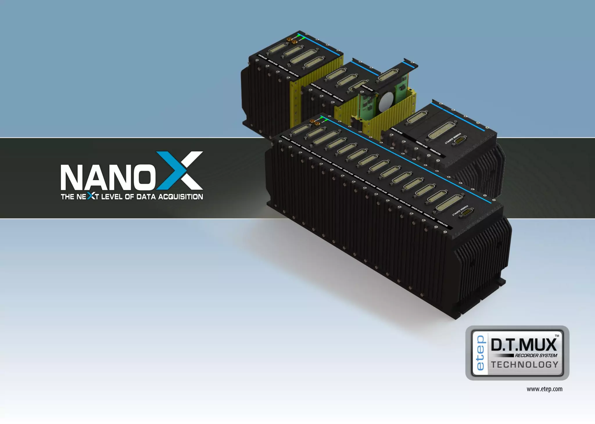
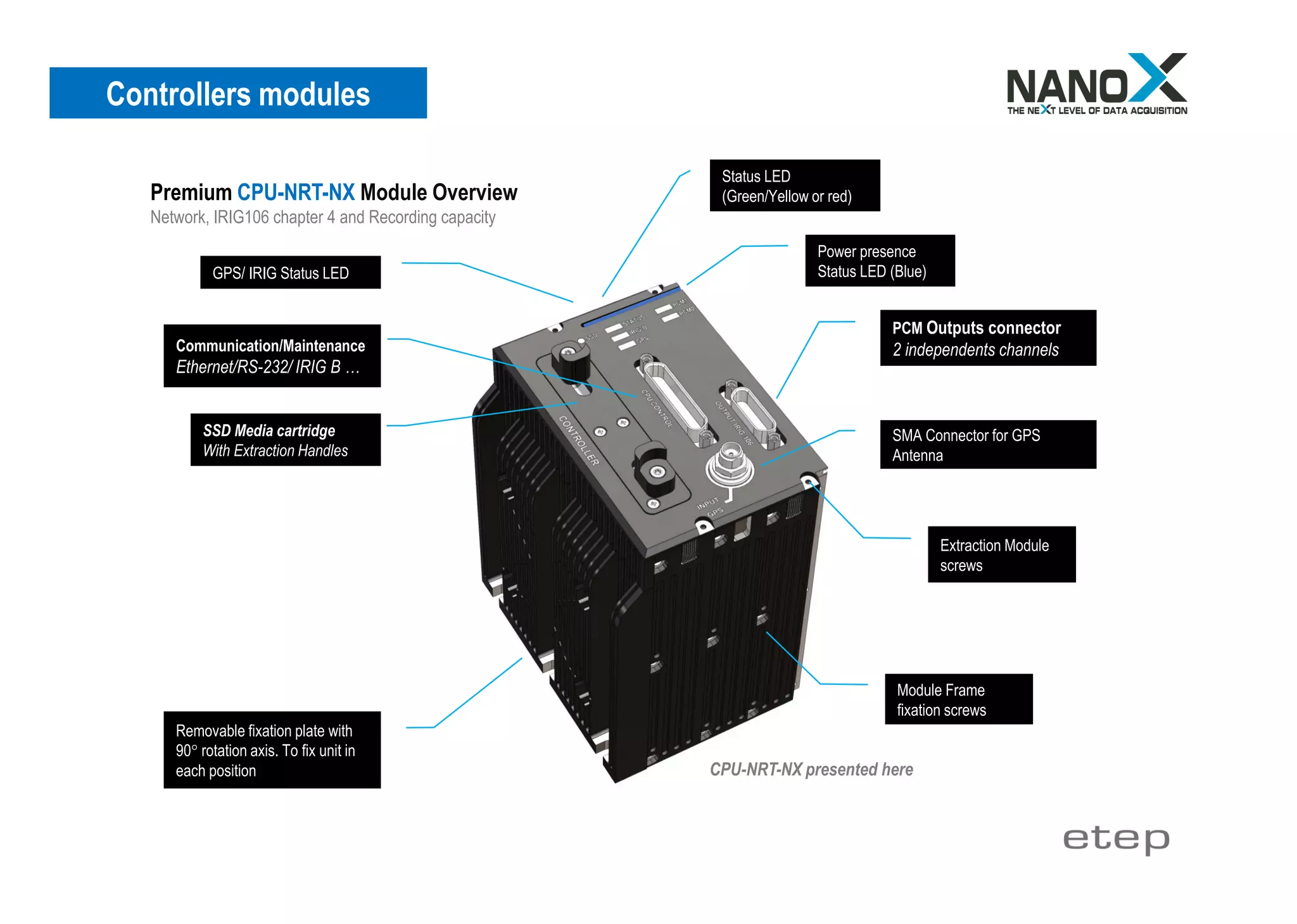
Status LED
(Green/Yellow or red)
GPS/ IRIG Status LED
Removable fixation plate with
90° rotation axis. To fix unit in
each position
Communication/Maintenance connector
Ethernet/RS-232/ IRIG B …
Module Frame
fixation screws
Extraction Module
screws
SMA Connector for GPS Antenna
Power presence
Status LED (Blue)
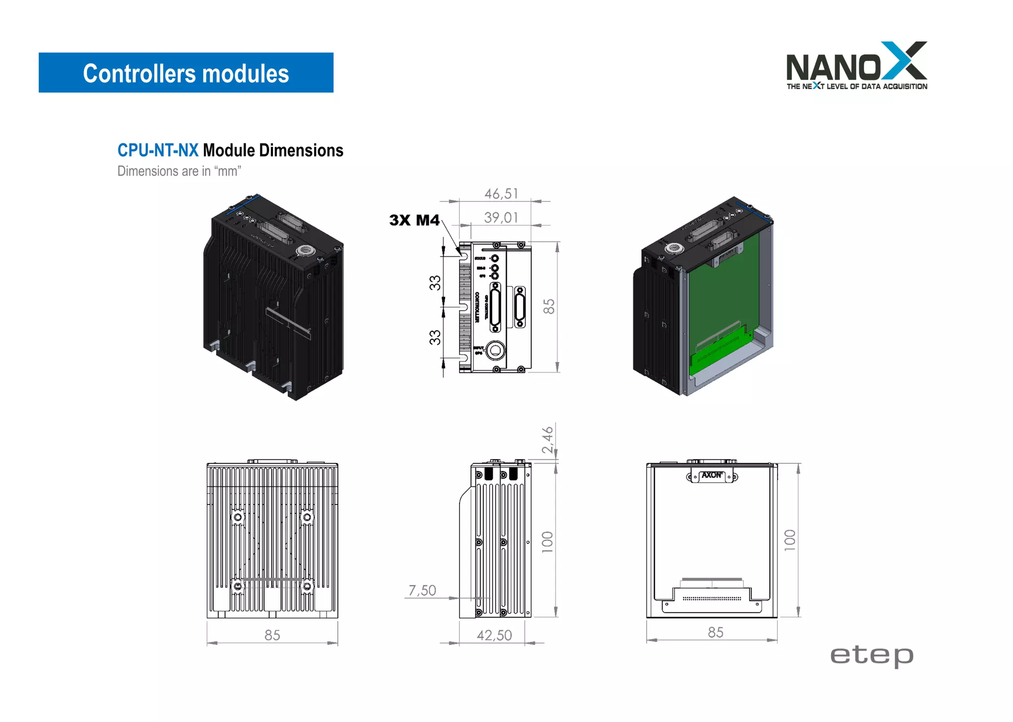
The NanoX Controllers are available in four different
version following your need, this one can integrate only
some basic functionalities or integrate transmission
and recording functionalities to transform your data
acquisition system to a real and powerful data
recorder.
Three mains controllers configurations:
[CPU-N-NX] Network capacity (For Master/Satellite(s) system).
[CPU-NR-NX] Network & Recording capacity.
[CPU-NT-NX] Network & IRIG 106, chapter 4 capacity.
Premium configuration:
[CPU-NRT-NX] Network, Recording and IRIG 106 chapter 4 capacity.
CPU-N-NX presented here
CPU-N-NX Module Overview
Network capacity (For Master/Satellite(s) system).](https://image.slidesharecdn.com/nanoxoverview-190626132756/75/NanoX-Overview-4-2048.jpg)
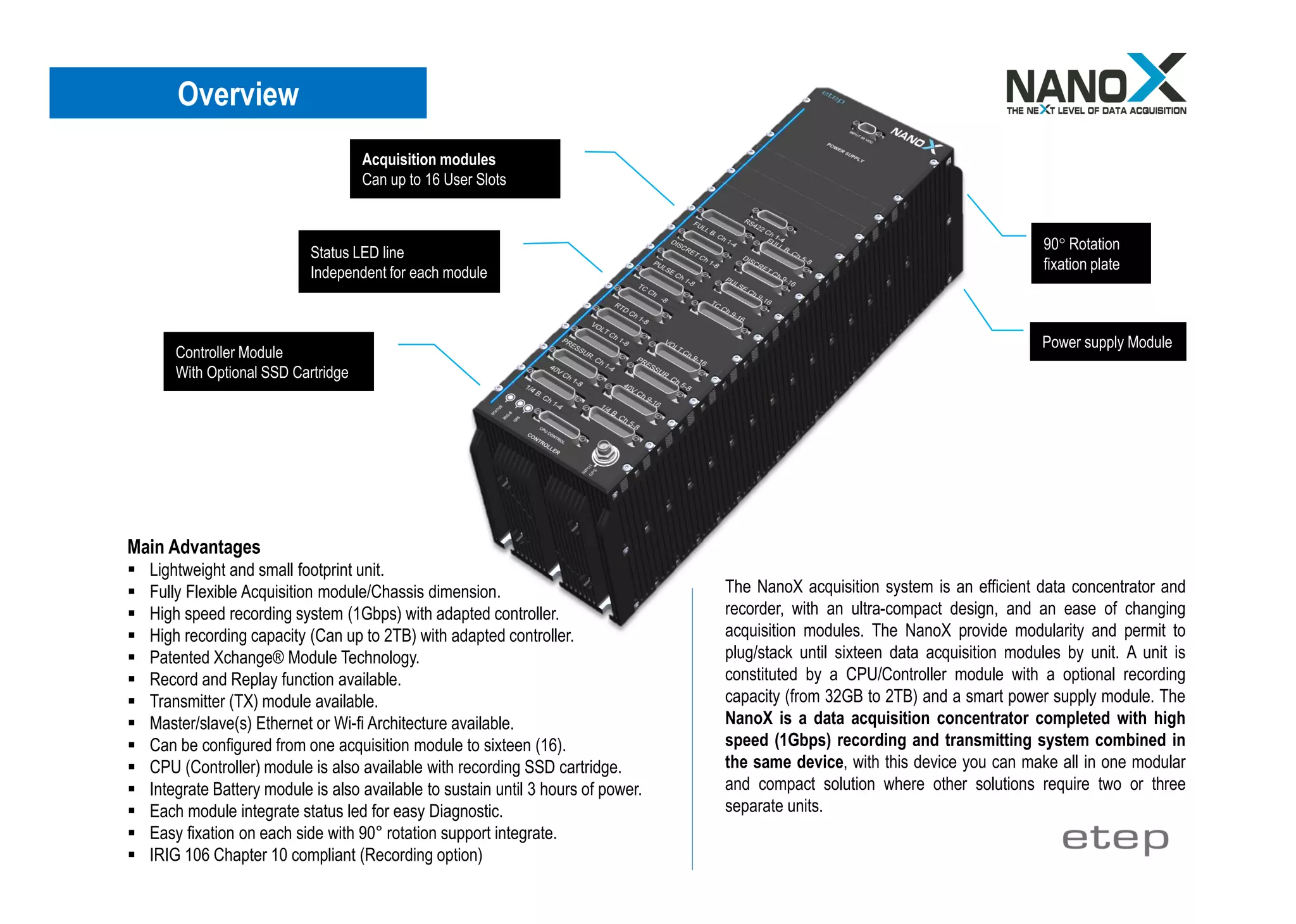
![Features/Utility channels
▪ Audio input
▪ Irig B Time input
▪ GPS input (Time, Position…)
▪ Support IEEE 1588 Time v2
▪ Discrete; ON/OFF and ON/OFF record
▪ Tricolor status outputs LED
▪ CPU, IRIG B, GPS status LED
RS 232 Communication
▪ Port for configuration
▪ Port for maintenance
Gigabit Ethernet
▪ Configuration/Control/Status/Download (from SSD)
▪ Real time transmitting for Real time visualization
▪ Network link with NanoX Satellites units
▪ PTP v2 Grandmaster Clock
Wi-Fi 802.11g [OPTION]
▪ Configuration/Status/Download (from SSD)
▪ Network link with NanoX Satellites units
▪ Real time transmitting (To master Unit/ To decom software).
Discrete used to the NanoX functioning
▪ Discrete; ON/OFF and ON/OFF record
▪ Tricolor outputs LED
▪ Outputs: 2 cathodes and anode for operating green, orange, red.
▪ Intensity outputs for LED: 20 mA max.
Audio channel
▪ Input: 1 volt efficient.
▪ Sample frequency 31.25KHz
▪ Band pass: 0 to 14.7KHz
▪ Input impedance: 1 MΩ
Input Connector
▪ MICRO D (MIL-DTL-83513) for data Input/output
▪ SMA for GPS input
Recoding Capacity
From 32GB to 2TB
Available with CPU-NR-NX or CPU-NRT-NX only.
Time stamping/Synchronization
▪ Internal Time/IRIG B Time
▪ Time accuracy 1 µsec
▪ GPS Time
▪ IEEE 1588 (PTP v2) –Precision Time Protocol
▪ Time Offset programmable
Irig B channel
▪ Input: Sinus 1000 Hz, modulation level 1/3- 3/3.
▪ Output IRIG B time generation (1pps TTL).
▪ Modulation: 8Volts P to P max.
▪ To 500mVolts P to P min.
▪ Input Impedance greater than 10 KΩ
▪ Loss of the Irig B, time continuous to progress on internal base time
▪ Second, minutes, Hours and days.
GPS Function
▪ SMA independent input.
▪ Second, minutes, Hours and days (UTC).
▪ GPS data GPRMC format (Latitude, Longitude, Ground speed)
▪ Satellite acquisition less than 50 Seconds (Clear Sky)
▪ Output IRIG B time generation from GPS (1pps TTL).
▪ NMEA output at a rate of 1Hz
▪ Compatible with GPS Patch Antenna
Internal Sensors
▪ Temperature sensor / Pressure sensor / Humidity sensor
Master/Slave(s) link
▪ By Gigabit Ethernet (GbE) with IEEE 1588 Time (Precision Time Protocol)
▪ By Wi-Fi 802.11g [OPTION]
Controllers modules](https://image.slidesharecdn.com/nanoxoverview-190626132756/75/NanoX-Overview-9-2048.jpg)
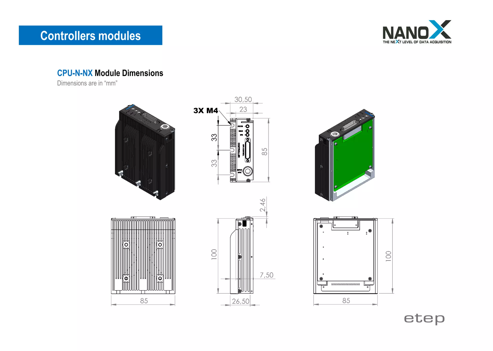
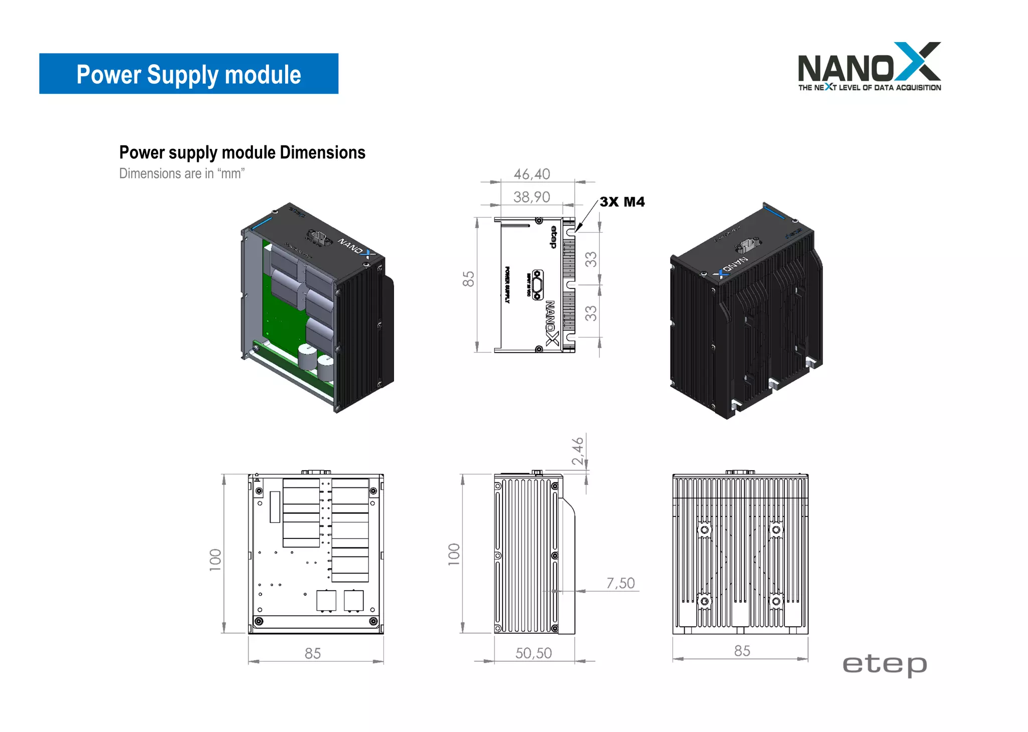
![Power Supply module
[POWER-NX] module
The power supply module is constituted by two electrical circuits
and is conform to MIL-STD-704F, one circuit DC-DC Converter
card, and another one is Ultra capacitor circuit who protect
NanoX installation from power interruption about 100
milliseconds. There is no battery and therefore no preventive
maintenance for power down protection. These modules are also
able to be powered by battery if aircraft power is not available.
▪ Can support 16 different user modules.
▪ Until 130 Watts of power distribution.
▪ Compliant MIL-STD-704F standard.
▪ Powerful Ultra-capacitor to prevent power cut.
▪ MICRO D (MIL-DTL-83513) connector.
▪ Can be Extended with Battery module
Module Connector
Type MICRO D (MIL-DLT-83513)
Power presence
Status LED
Removable fixation plate with
90° rotation axis. To fix unit in
each positionModule Frame
fixation screws
MIL-STD-704F qualified, this module assures over voltage protection and
permit to protect and assure data safety during acquisition or recording in
case of power failure. There is no battery and therefore no preventive
maintenance, for power down protection. These modules are also able to
be powered by battery if aircraft power is not available.
Temperature Management: Power supply module is also the seat of a
smart and powerful Temperature control processor who permit the
protection of all unit in case of aggressive temperature environment, this
one monitors the temperature of each module and operate heating or
cooling process following the environment encountered.](https://image.slidesharecdn.com/nanoxoverview-190626132756/75/NanoX-Overview-11-2048.jpg)
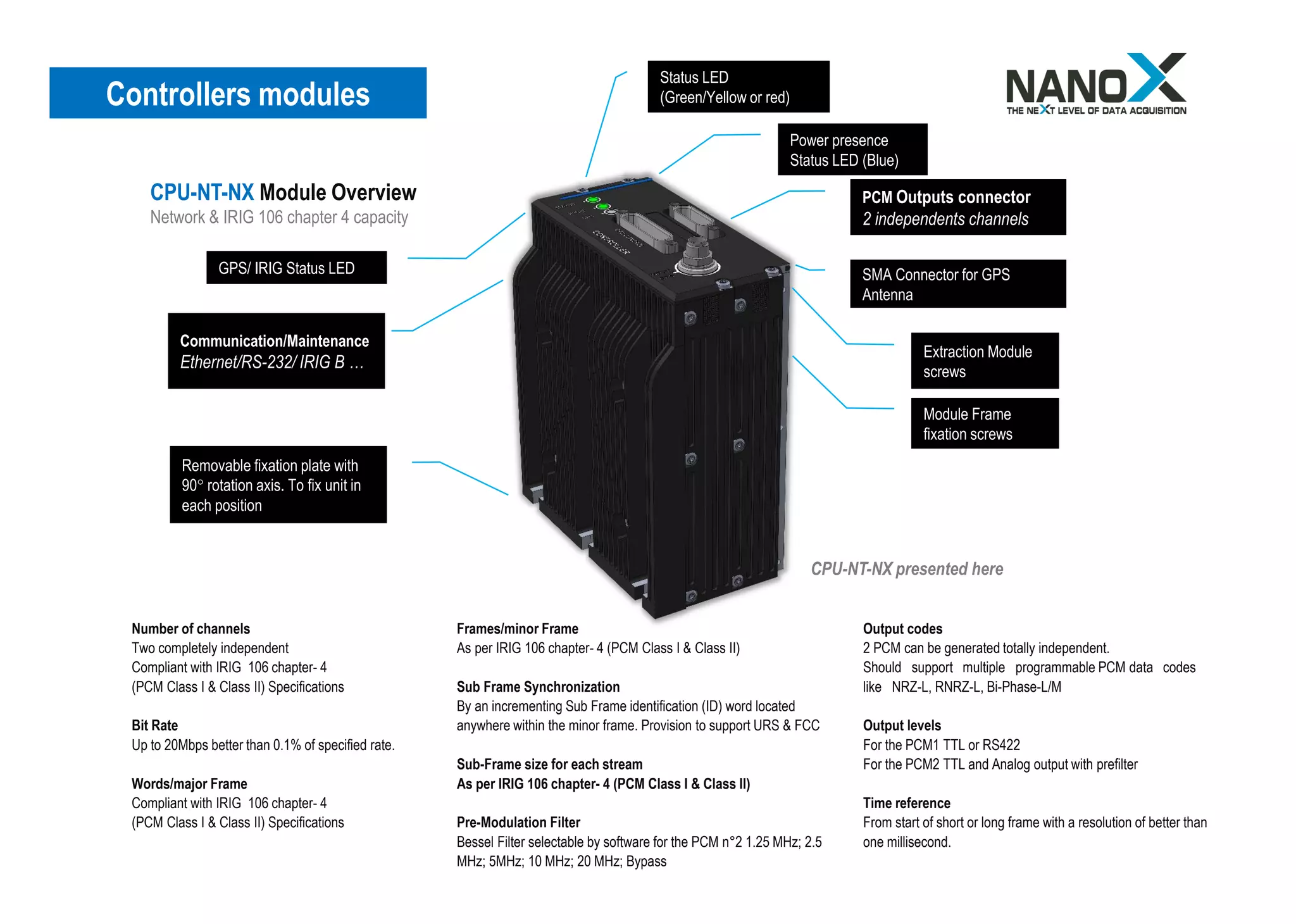
![Environmental
Vibration
MIL-STD-810G method 514.4
0.04 g² of 5 to 2000 Hz,
1 hour per axis (3 axis)
Linear Acceleration
MIL STD 810F,
15g for one minute in six directions.
Shocks
MIL-STD-810F method 516.5/516.3
100g, 11ms (6 axis) in functioning
Operating Temperature
- 40°C to + 71°C.
MIL-STD-810G method 502.5 procedure II
MIL-STD-810G method 501.5 procedure II
Extreme of temperature (Short period)
- 55° C to 85°C [Short period no destructive]
Test MIL STD 810F
Extreme temperature cannot guarantee data integrity
Humidity in use
5% to 95 % without condensation
MIL STD 810F
Electromagnetic compatibility (EMI)
MIL STD 461 Rev. G (2015)
CE101 Power leads 30Hz to 10KHz
CE102 Power leads 10KHz to 10MHZ
RE101 Magnetic field 30Hz to 100KHz
RE102 Electric field 10KHz to 18GHz
Altitude and decompression
Min: -1500 feet, max: 60,000 feet
With 12.000 feet/minute
(420Kpa/minute), MIL STD 810G.
Altitude max. Storage
No limit
Storage temperature
- 55°C to + 90°C
Humidity in storage
5% to 95 % without condensation
MIL-STD-810G method 507.4
Aircraft Electrical Power Characteristics
MIL-STD-704 Rev. F (2004)
Prevent power down < 60 milliseconds](https://image.slidesharecdn.com/nanoxoverview-190626132756/75/NanoX-Overview-14-2048.jpg)


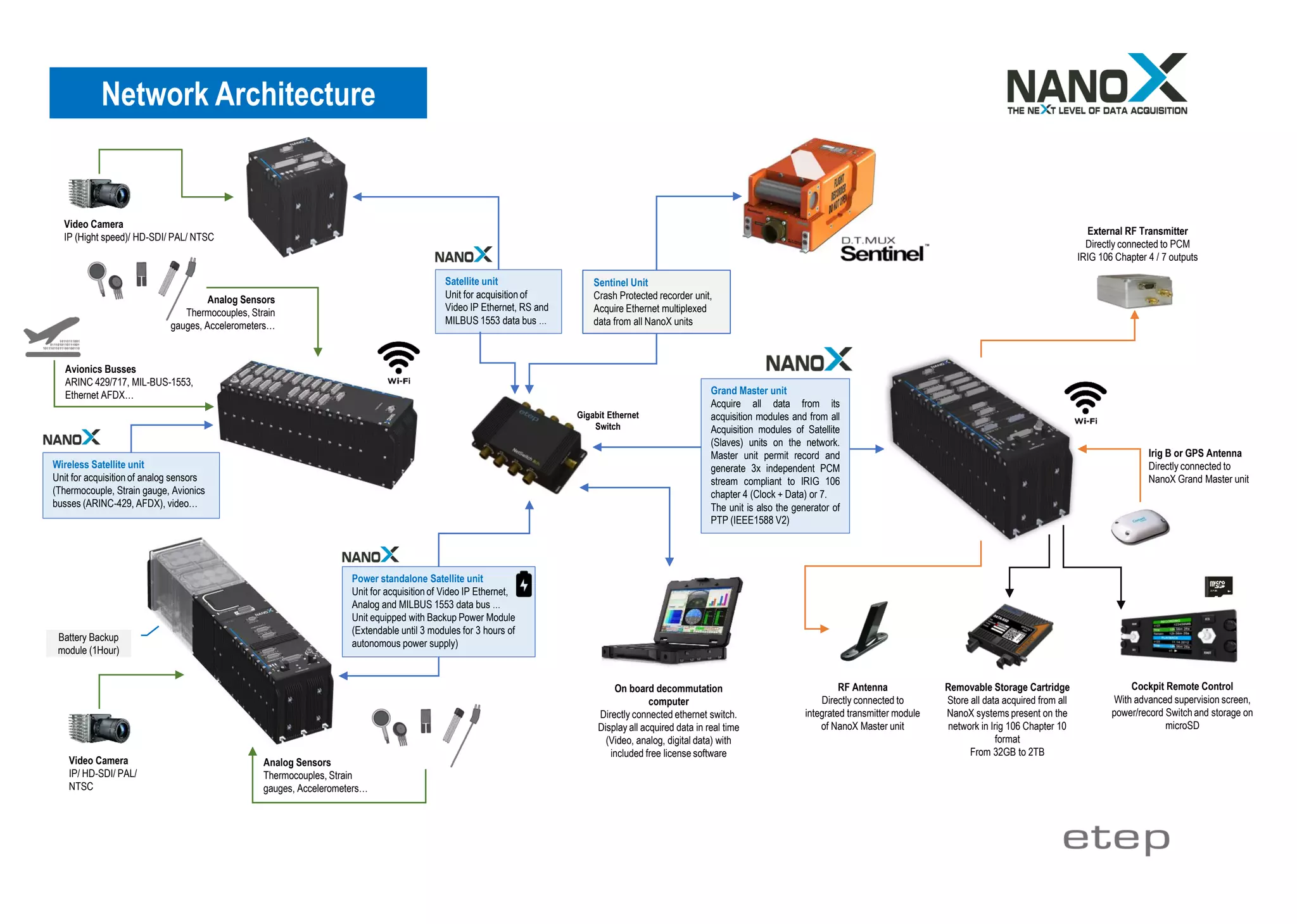


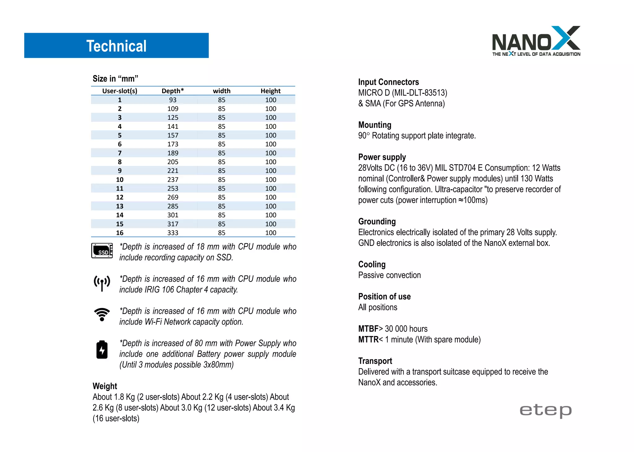
The Nanox acquisition system is a compact and modular data concentrator capable of supporting up to 16 user slots and offering high-speed recording (1 Gbps) with capacities ranging from 32GB to 2TB. It includes features such as an easy module swap design, built-in power supply with ultra-capacitors for backup, and compliance with various military standards for durability. The system is intended for flexible and efficient data acquisition in challenging environments, allowing for quick maintenance and adaptability to user needs.


