SlideShare a Scribd company logo
Name: Israel Vega
High School: Immokalee High School
Research Advisor: Dr. Kevin S. Jones, University of Florida, Gainesville
Research Site: Department of Materials Science, University of Florida, Gainesville
ABSTRACT
With ever shrinking transistors, integrated circuits continue to have more computing power
to perform faster computations. According to Moore’s Law, the number of transistor’s per
square inch in integrated circuits doubles every year. For this trend to continue,
semiconductor materials must be improved to fabricate smaller faster transistors . That is
why there is a high interest of using novel materials, specifically N-type InAs grown on Si. N-
type InAs has a higher concentration of free electrons, since dopants are introduced to
modify its electrical properties. InAs has a high electron mobility and narrow band gap that
allows fast transfer of electrons to operate signals. InAs and Si both have a diamond cubic
crystalline structure which is ideal ,because similar crystal lattices between semiconductors
will minimize defects such as vacancies and misalignments in the arrangement of atoms in
the crystal. Defects in crystal lattice degrade the performance of the semiconductor
conductivity. InAs has a larger diamond cubic structure than Si which limits its performance
to be used in transistors. N-type MOCVD thin films of InAs were annealed at a higher
temperature than they were grown in to observe changes in their structure. Samples of
annealed and non-annealed InAs were analyzed for their electrical properties by using Hall
Effect Measurements to determine conductivity, carrier concentration, electron mobility,
resistivity, and sheet resistance. Plan view TEM observations were conducted to analyze the
samples microstructure for differences in defect density.
INTRODUCTION
All of electronic devices are made up of transistors that amplify or block electrical signals
which operate in a binary system of on and off signals. With many networking transistors,
signals can be sent, stored and translated into complex combinations to perform operations
on your electronic device. Transistors are made of semiconductor material which uses both
its conductive and insulating properties to amplify or block electrical signals in devices. Over
the years, the number of transistors on electrical circuits grows and the size of the transistors
shrinks. Smaller and numerous transistors establishes more computing power to operate
more electrical signals. This exponential rate is known as Moore's law and for this
observation to hold true, semiconductor materials must be improved for smaller and faster
transistors, which is why there is a high interest of using N-type InAs on Si. N-type InAs has
high electron mobility and a narrow band gap to allow faster transfer of electrons. InAs and Si
both have a diamond cubic crystalline structure; however InAs has a larger diamond cubic
structure than Si which limits its performance to be used as a semiconductor. In this project,
grown thin films of InAs were analyzed for the effects of annealing on the InAs’s conductivity,
carrier concentration, and electron mobility.
RESULTSMETHOD
Samples of N-Type InAs grown on Si wafer were prepared in 1cm² squares for Hall Effect
Measurement and Plane View TEM observation. A non-annealed sample served as a control
that had MOCVD InAs grown on Si between 300°C and 350°C and was analyzed for its
electrical properties by conducting a Hall Effect Measurement by setting the sample on a four
probe Hall Effect sensor. Each corner was coated with the soft metal Indium to connect
contacts with the four probes. It’s important that the contacts on each of the corners are
ohmic to receive an accurate reading from Hall Effect measurement and can be determined
by using a curve tracer. These samples need to be coated by an atomic layer deposition of
Aluminum Oxide to keep the Arsenide from evaporating during the annealing process. The
sample is then annealed in a furnace at 550 °C for 10 minutes with Argon purging to keep the
sample from reacting with the atmosphere at this high temperature. The sample is then left
to cool at room temperature. After cooling, the annealed sample is bathed in a buffered
oxide etch with hydrofluoric acid for 10 minutes to remove the Aluminum Oxide coating. The
annealed sample is bathed in water to remove the acid and then dried. A Hall Effect
Measurement is conducted on the annealed sample to analyze conductivity, carrier
concentration, electron mobility, resistivity and sheet resistance. Both annealed and non-
annealed samples are prepared for Plane-view TEM analysis. Using a Focused Ion Beam, the
samples will have a small surface of its InAs etched off to analyze for defect density by TEM
analysis. It’s important to have very thin samples for Plan-view TEM analysis. If the sample is
too thick, the electrons won’t be able to pass right through the sample and not properly view
internal defects.
DISCUSSION
Hall Effect Measurements show that annealed samples have higher sheet resistance and
lower mobility than non-annealed samples. In fact, the average mobility of non-annealed
InAs was -29.633 (cm2/Vs), average sheet number was -2.6E13 (cm-2) and the average sheet
resistance was 8,283.5 (Ohm/cm2). The average mobility of the annealed sample was -
27.4383(cm2/Vs), average sheet number was -3.0945E13 (cm-2) and average sheet
resistance was 13,189.5 (Ohm/cm2). This a 7% decrease of mobility in the annealed sample,
19% increase in sheet number, and a 59% increase in sheet resistance. The Hall Effect
Analysis also shows miniscule change in the amount of carriers, which suggests annealing at
550°C does not deactivate or activate dopants. The decrease in mobility of the annealed
sample can be seen in the TEM images. Strains and defects are still distributed across the
annealed sample. Because the annealed sample has a lower mobility than the non-annealed,
there must be a higher defect concentration in the annealed sample than the non-annealed.
Effects of Annealing in Indium Arsenide Grown on Silicon
Semiconductor
Annealing is a type of heating treatment that can relieve the stresses and strains in the crystal
lattice of semiconductors. The intense heat diffuses the arrangement of atoms and rearranges
the crystal lattice. This heat treatment alters the electrical properties and can reduce
crystallographic defects in semiconductors. InAs grown on Si has a high interest to be used in
semiconductor material since it has a narrow band gap and high electron mobility. InAs and Si
both have a diamond cubic crystal structure; however InAs has a larger diamond cubic structure
than Si. The difference in size lattices between the InAs and Si limits its electrical properties
because it will cause variances in its structure. The heat treatment given to InAs grown Si did
not improve its electrical properties. There was lower mobility due to more defects in the crystal
lattice and higher sheet resistance. Since InAs has a larger diamond cubic structure than Si, InAs
has to stress and strain to grow onto the small Si crystal lattice. TEM images of the annealing
treatment suggest that the stresses in the InAs were relieved, which caused defects to form as
the crystal lattice diffused and rearranged. Any heat treatment in the fabrication of growing
InAs on Si should be avoided. Heat treatment has a negative effect on the mobility and
resistance in thin 20 nanometer InAs grown on Si.

More Related Content

What's hot

ECS 2008 Presentaion
ECS 2008 PresentaionECS 2008 Presentaion
ECS 2008 Presentaion
pinkfans5
 
DavidLaFehrEEResearchProject
DavidLaFehrEEResearchProjectDavidLaFehrEEResearchProject
DavidLaFehrEEResearchProject
David LaFehr
 
Design Study on Nuclear Transportation Cask
Design Study on Nuclear Transportation CaskDesign Study on Nuclear Transportation Cask
Design Study on Nuclear Transportation Cask
Zhi
 
02 insulators and conductors
02 insulators and conductors02 insulators and conductors
02 insulators and conductors
mrtangextrahelp
 

What's hot (20)

Dielectric materials
Dielectric materialsDielectric materials
Dielectric materials
 
Microwave ceramics
Microwave ceramicsMicrowave ceramics
Microwave ceramics
 
UNDERGROUND CABLE
UNDERGROUND CABLEUNDERGROUND CABLE
UNDERGROUND CABLE
 
ECS 2008 Presentaion
ECS 2008 PresentaionECS 2008 Presentaion
ECS 2008 Presentaion
 
Conductors and insulators
Conductors and insulatorsConductors and insulators
Conductors and insulators
 
DavidLaFehrEEResearchProject
DavidLaFehrEEResearchProjectDavidLaFehrEEResearchProject
DavidLaFehrEEResearchProject
 
Electrical Conductor
Electrical ConductorElectrical Conductor
Electrical Conductor
 
Types of Circuit Breakers
Types of Circuit BreakersTypes of Circuit Breakers
Types of Circuit Breakers
 
Chemical pipe earthing
Chemical pipe earthingChemical pipe earthing
Chemical pipe earthing
 
Lightnng protection as Per IEC 62305 Presentaton by JMV LPS LTD
Lightnng protection  as Per IEC 62305 Presentaton by JMV LPS LTDLightnng protection  as Per IEC 62305 Presentaton by JMV LPS LTD
Lightnng protection as Per IEC 62305 Presentaton by JMV LPS LTD
 
Conductors and its types
Conductors and its typesConductors and its types
Conductors and its types
 
Characteristics of cables
Characteristics of cablesCharacteristics of cables
Characteristics of cables
 
Design Study on Nuclear Transportation Cask
Design Study on Nuclear Transportation CaskDesign Study on Nuclear Transportation Cask
Design Study on Nuclear Transportation Cask
 
Types of insulator
Types of insulatorTypes of insulator
Types of insulator
 
Electrical Engineering Material Part-I
Electrical Engineering Material Part-IElectrical Engineering Material Part-I
Electrical Engineering Material Part-I
 
02 insulators and conductors
02 insulators and conductors02 insulators and conductors
02 insulators and conductors
 
Syamsir Abduh-Proteksi petir-2003
Syamsir Abduh-Proteksi petir-2003Syamsir Abduh-Proteksi petir-2003
Syamsir Abduh-Proteksi petir-2003
 
Conductors and Insulators | Physics
Conductors and Insulators | PhysicsConductors and Insulators | Physics
Conductors and Insulators | Physics
 
Self Potential Method (Electrical Survey)
Self Potential Method (Electrical Survey)Self Potential Method (Electrical Survey)
Self Potential Method (Electrical Survey)
 
Significance Of Resistance Temperature Device
Significance Of Resistance Temperature DeviceSignificance Of Resistance Temperature Device
Significance Of Resistance Temperature Device
 

Similar to Poster

2001 field based scanning tunneling microscope manipulation of antimony dimer...
2001 field based scanning tunneling microscope manipulation of antimony dimer...2001 field based scanning tunneling microscope manipulation of antimony dimer...
2001 field based scanning tunneling microscope manipulation of antimony dimer...
pmloscholte
 
Yutong Liu - Final Report - Anodized Aluminium Oxide (AAO)
Yutong Liu - Final Report - Anodized Aluminium Oxide (AAO)Yutong Liu - Final Report - Anodized Aluminium Oxide (AAO)
Yutong Liu - Final Report - Anodized Aluminium Oxide (AAO)
Yutong Liu
 
Highly thermally conductive dielectric coatings produced by Plasma Electrolyt...
Highly thermally conductive dielectric coatings produced by Plasma Electrolyt...Highly thermally conductive dielectric coatings produced by Plasma Electrolyt...
Highly thermally conductive dielectric coatings produced by Plasma Electrolyt...
Tamires Tah
 
Microelectrodes ch01
Microelectrodes ch01Microelectrodes ch01
Microelectrodes ch01
Mukesh Samta
 
2015NNINreuRA_King
2015NNINreuRA_King2015NNINreuRA_King
2015NNINreuRA_King
Andrew King
 
The effect of magnetic field direction on thermoelectric and thermomagnetic c...
The effect of magnetic field direction on thermoelectric and thermomagnetic c...The effect of magnetic field direction on thermoelectric and thermomagnetic c...
The effect of magnetic field direction on thermoelectric and thermomagnetic c...
Muhammid Al-Baghdadi
 

Similar to Poster (20)

Improving the Dielectric properties of SAMs
Improving the Dielectric properties of SAMsImproving the Dielectric properties of SAMs
Improving the Dielectric properties of SAMs
 
J010126267
J010126267J010126267
J010126267
 
Aluminum Oxide-Silver Nanoparticle Interfaces for Memristive Applications
Aluminum Oxide-Silver Nanoparticle Interfaces for Memristive ApplicationsAluminum Oxide-Silver Nanoparticle Interfaces for Memristive Applications
Aluminum Oxide-Silver Nanoparticle Interfaces for Memristive Applications
 
Annealing and Microstructural Characterization of Tin-Oxide Based Thick Film ...
Annealing and Microstructural Characterization of Tin-Oxide Based Thick Film ...Annealing and Microstructural Characterization of Tin-Oxide Based Thick Film ...
Annealing and Microstructural Characterization of Tin-Oxide Based Thick Film ...
 
2001 field based scanning tunneling microscope manipulation of antimony dimer...
2001 field based scanning tunneling microscope manipulation of antimony dimer...2001 field based scanning tunneling microscope manipulation of antimony dimer...
2001 field based scanning tunneling microscope manipulation of antimony dimer...
 
Yutong Liu - Final Report - Anodized Aluminium Oxide (AAO)
Yutong Liu - Final Report - Anodized Aluminium Oxide (AAO)Yutong Liu - Final Report - Anodized Aluminium Oxide (AAO)
Yutong Liu - Final Report - Anodized Aluminium Oxide (AAO)
 
properties of nanomaterials
properties of nanomaterialsproperties of nanomaterials
properties of nanomaterials
 
dokumen.tips_physics-investigatory-project-on-ohms-law-58f9dcf82b4f5.pptx
dokumen.tips_physics-investigatory-project-on-ohms-law-58f9dcf82b4f5.pptxdokumen.tips_physics-investigatory-project-on-ohms-law-58f9dcf82b4f5.pptx
dokumen.tips_physics-investigatory-project-on-ohms-law-58f9dcf82b4f5.pptx
 
Highly thermally conductive dielectric coatings produced by Plasma Electrolyt...
Highly thermally conductive dielectric coatings produced by Plasma Electrolyt...Highly thermally conductive dielectric coatings produced by Plasma Electrolyt...
Highly thermally conductive dielectric coatings produced by Plasma Electrolyt...
 
The Albedo of Metallic Nanoparticles Computed from FDTD
The Albedo of Metallic Nanoparticles Computed from FDTDThe Albedo of Metallic Nanoparticles Computed from FDTD
The Albedo of Metallic Nanoparticles Computed from FDTD
 
Fabrication and characterization of nickel
Fabrication and characterization of nickelFabrication and characterization of nickel
Fabrication and characterization of nickel
 
Microelectrodes ch01
Microelectrodes ch01Microelectrodes ch01
Microelectrodes ch01
 
2015NNINreuRA_King
2015NNINreuRA_King2015NNINreuRA_King
2015NNINreuRA_King
 
Physics Project.docx.pptx
Physics Project.docx.pptxPhysics Project.docx.pptx
Physics Project.docx.pptx
 
The effect of magnetic field direction on thermoelectric and thermomagnetic c...
The effect of magnetic field direction on thermoelectric and thermomagnetic c...The effect of magnetic field direction on thermoelectric and thermomagnetic c...
The effect of magnetic field direction on thermoelectric and thermomagnetic c...
 
Studies on in-Doped Zno Transparent Conducting thin Films
Studies on in-Doped Zno Transparent Conducting thin FilmsStudies on in-Doped Zno Transparent Conducting thin Films
Studies on in-Doped Zno Transparent Conducting thin Films
 
Scanning Tunneling Microscope
Scanning Tunneling MicroscopeScanning Tunneling Microscope
Scanning Tunneling Microscope
 
Ultrasonic welding of titanium alloy TiAl6V4 to aluminium alloy AA6111
Ultrasonic welding of titanium alloy TiAl6V4 to aluminium alloy AA6111Ultrasonic welding of titanium alloy TiAl6V4 to aluminium alloy AA6111
Ultrasonic welding of titanium alloy TiAl6V4 to aluminium alloy AA6111
 
1-s2.0-S1369800114000055-main
1-s2.0-S1369800114000055-main1-s2.0-S1369800114000055-main
1-s2.0-S1369800114000055-main
 
DC Conductivity of Composite Silicon Thin Films
DC Conductivity of Composite Silicon Thin FilmsDC Conductivity of Composite Silicon Thin Films
DC Conductivity of Composite Silicon Thin Films
 

Poster

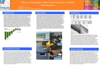
  • 1. Name: Israel Vega High School: Immokalee High School Research Advisor: Dr. Kevin S. Jones, University of Florida, Gainesville Research Site: Department of Materials Science, University of Florida, Gainesville ABSTRACT With ever shrinking transistors, integrated circuits continue to have more computing power to perform faster computations. According to Moore’s Law, the number of transistor’s per square inch in integrated circuits doubles every year. For this trend to continue, semiconductor materials must be improved to fabricate smaller faster transistors . That is why there is a high interest of using novel materials, specifically N-type InAs grown on Si. N- type InAs has a higher concentration of free electrons, since dopants are introduced to modify its electrical properties. InAs has a high electron mobility and narrow band gap that allows fast transfer of electrons to operate signals. InAs and Si both have a diamond cubic crystalline structure which is ideal ,because similar crystal lattices between semiconductors will minimize defects such as vacancies and misalignments in the arrangement of atoms in the crystal. Defects in crystal lattice degrade the performance of the semiconductor conductivity. InAs has a larger diamond cubic structure than Si which limits its performance to be used in transistors. N-type MOCVD thin films of InAs were annealed at a higher temperature than they were grown in to observe changes in their structure. Samples of annealed and non-annealed InAs were analyzed for their electrical properties by using Hall Effect Measurements to determine conductivity, carrier concentration, electron mobility, resistivity, and sheet resistance. Plan view TEM observations were conducted to analyze the samples microstructure for differences in defect density. INTRODUCTION All of electronic devices are made up of transistors that amplify or block electrical signals which operate in a binary system of on and off signals. With many networking transistors, signals can be sent, stored and translated into complex combinations to perform operations on your electronic device. Transistors are made of semiconductor material which uses both its conductive and insulating properties to amplify or block electrical signals in devices. Over the years, the number of transistors on electrical circuits grows and the size of the transistors shrinks. Smaller and numerous transistors establishes more computing power to operate more electrical signals. This exponential rate is known as Moore's law and for this observation to hold true, semiconductor materials must be improved for smaller and faster transistors, which is why there is a high interest of using N-type InAs on Si. N-type InAs has high electron mobility and a narrow band gap to allow faster transfer of electrons. InAs and Si both have a diamond cubic crystalline structure; however InAs has a larger diamond cubic structure than Si which limits its performance to be used as a semiconductor. In this project, grown thin films of InAs were analyzed for the effects of annealing on the InAs’s conductivity, carrier concentration, and electron mobility. RESULTSMETHOD Samples of N-Type InAs grown on Si wafer were prepared in 1cm² squares for Hall Effect Measurement and Plane View TEM observation. A non-annealed sample served as a control that had MOCVD InAs grown on Si between 300°C and 350°C and was analyzed for its electrical properties by conducting a Hall Effect Measurement by setting the sample on a four probe Hall Effect sensor. Each corner was coated with the soft metal Indium to connect contacts with the four probes. It’s important that the contacts on each of the corners are ohmic to receive an accurate reading from Hall Effect measurement and can be determined by using a curve tracer. These samples need to be coated by an atomic layer deposition of Aluminum Oxide to keep the Arsenide from evaporating during the annealing process. The sample is then annealed in a furnace at 550 °C for 10 minutes with Argon purging to keep the sample from reacting with the atmosphere at this high temperature. The sample is then left to cool at room temperature. After cooling, the annealed sample is bathed in a buffered oxide etch with hydrofluoric acid for 10 minutes to remove the Aluminum Oxide coating. The annealed sample is bathed in water to remove the acid and then dried. A Hall Effect Measurement is conducted on the annealed sample to analyze conductivity, carrier concentration, electron mobility, resistivity and sheet resistance. Both annealed and non- annealed samples are prepared for Plane-view TEM analysis. Using a Focused Ion Beam, the samples will have a small surface of its InAs etched off to analyze for defect density by TEM analysis. It’s important to have very thin samples for Plan-view TEM analysis. If the sample is too thick, the electrons won’t be able to pass right through the sample and not properly view internal defects. DISCUSSION Hall Effect Measurements show that annealed samples have higher sheet resistance and lower mobility than non-annealed samples. In fact, the average mobility of non-annealed InAs was -29.633 (cm2/Vs), average sheet number was -2.6E13 (cm-2) and the average sheet resistance was 8,283.5 (Ohm/cm2). The average mobility of the annealed sample was - 27.4383(cm2/Vs), average sheet number was -3.0945E13 (cm-2) and average sheet resistance was 13,189.5 (Ohm/cm2). This a 7% decrease of mobility in the annealed sample, 19% increase in sheet number, and a 59% increase in sheet resistance. The Hall Effect Analysis also shows miniscule change in the amount of carriers, which suggests annealing at 550°C does not deactivate or activate dopants. The decrease in mobility of the annealed sample can be seen in the TEM images. Strains and defects are still distributed across the annealed sample. Because the annealed sample has a lower mobility than the non-annealed, there must be a higher defect concentration in the annealed sample than the non-annealed. Effects of Annealing in Indium Arsenide Grown on Silicon Semiconductor Annealing is a type of heating treatment that can relieve the stresses and strains in the crystal lattice of semiconductors. The intense heat diffuses the arrangement of atoms and rearranges the crystal lattice. This heat treatment alters the electrical properties and can reduce crystallographic defects in semiconductors. InAs grown on Si has a high interest to be used in semiconductor material since it has a narrow band gap and high electron mobility. InAs and Si both have a diamond cubic crystal structure; however InAs has a larger diamond cubic structure than Si. The difference in size lattices between the InAs and Si limits its electrical properties because it will cause variances in its structure. The heat treatment given to InAs grown Si did not improve its electrical properties. There was lower mobility due to more defects in the crystal lattice and higher sheet resistance. Since InAs has a larger diamond cubic structure than Si, InAs has to stress and strain to grow onto the small Si crystal lattice. TEM images of the annealing treatment suggest that the stresses in the InAs were relieved, which caused defects to form as the crystal lattice diffused and rearranged. Any heat treatment in the fabrication of growing InAs on Si should be avoided. Heat treatment has a negative effect on the mobility and resistance in thin 20 nanometer InAs grown on Si.