Poster
•
0 likes•127 views

The historic Checkered House Bridge in Richmond, Vermont underwent a widening project to expand its width from 20 feet to 30 feet. Engineers from Finley Engineering Group developed a innovative system to widen the bridge by cutting and moving the entire north truss chord 12.5 feet using a hydraulic jack and roller system. Over two days, the 65-ton north truss was carefully moved into its new position at a rate of 2 feet per hour. Approximately 120 tons of new steel was added to join the trusses in the widened section while preserving 80% of the original bridge's steel members. The $13.9 million project is scheduled to reopen the bridge to traffic in June 2013 while maintaining the bridge's historic integrity.

Recommended
More Related Content
What's hot
What's hot (20)
Similar to Poster
Similar to Poster (20)
Poster
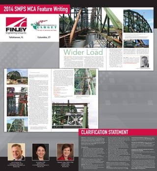
- 1. Columbia, CTTallahassee, FL A historic Vermont bridge gets a second life, thanks to a widening project facilitated by a hydraulic jack side-launching system. Wider LoadWHEN THE HISTORIC, 350-ft-long steel truss Checkered House Bridge was built in 1929 across the Winooski River in Richmond, Vt., it replaced yet another historic bridge: an 1800s-era wooden covered bridge that was severely damaged in the Great Flood of 1927. Over time, however, the massive steel structure had been restricted to increasingly lower load limits. This eliminated a major and convenient option for commercial trucks to service the area—just minutes from Burlington in Chittenden County, the most populated county in the state—for nearly two decades. After considering various alternatives and public input, the Vermont Agency of Transportation (VTrans) decided to keep the bridge in place and upgrade it to modern standards, which included expanding the curb-to-curb width from 20 ft. to 30 ft. “The steel trusses are in very good shape, except for the flooring members and decking, so it still has a significant life span,” explains Carolyn Carlson, structures project manager with VTrans. “Being able to reuse the bridge for its original intent in its original location definitely came into play.” Carlson has been involved with this bridge since 1990, when the concrete deck was originally considered for replacement. She notes that this is the first time a steel truss bridge of this magni- tude has been widened by separating a truss and reattaching it using new steel supports. The project also marks VTrans’ second 40 MODERN STEEL CONSTRUCTION DECEMBER 2012 BY JERRY PFUNTNER, P.E. DECEMBER 2012 MODERN STEEL CONSTRUCTION 41 ➤ design-build project ever and includes the reconstruction and realignment of Route 2, Kenyon Road and Johnnie Brook Road. The Checkered House Bridge is the state’s only Pennsylvania through-truss bridge, which is based on the Pratt truss and characterized by half-length struts or ties in the top, bottom or both parts of the panels. “Part of the challenge was to be able to clearly delineate the original, aged, green historic steel members from the new ones—similar to small homestead farm- houses with distinct additions over time that dot the Vermont landscape,” Carlson says. “Rather than a symmetrical look that mimics the original design, there is a vis- ible distinction that preserves and adds to history at the same time.” The design-build team of CHA and Harrison and Burrowes brought in ➤ Jerry Pfuntner is project manager for Finley Engineering Group in Tallahassee, Fla., an engineering firm with specialized expertise in complex bridge projects. Pfuntner conceptualized and developed the specialized falsework and hydraulic launching system for the Checkered House Bridge. He can be reached at jerry.pfuntner@finleyengineeringgroup.com. ➤ Tallahassee-based Finley Engineering Group (FINLEY) early in the bid process. “Due to the historical significance of the bridge, we had to develop a way to preserve as much of the original truss as possible, maintaining all portals and sway frames, while widening the structure and increasing load carrying capacity,” says David Vieni, P.E., project engineer with CHA. The FINLEY-designed jack and roller side-launching system allowed the team to save 80% of the original truss, Fitzgerald & Halliday, Inc.Fitzgerald & Halliday, Inc. Jared Katz Jared Katz The curb-to-curb width of the bridge was expanded from 20 ft. to 30 ft. The entire north truss chord was moved 12 ft, 6 in. Ten specially designed 18-in. stroke capacity hydraulic ram systems were placed on the top and bottom chords and at each abutment, and provided carefully monitored con- stant pressure to nudge the 65-ton north truss on Hilman rollers to its new location. reducing the need for additional steel. The 36-month, $13.9 million project is on schedule to have the bridge open for traffic in June 2013.Approximately 120 tons of new steel was added for the widening project. Hydraulic Help FINLEY developed and implemented the concept to widen the truss bridge by cutting and carefully moving the entire north truss chord 12 ft, 6 in. To maintain the historical integ- rity of the original bridge, nearly all of its steel members were retained and new structural bracing members were installed within the widened portion only. The innovative falsework and jacking system allowed the north truss to be moved, with lateral support being provided from the south truss system. The south truss was designed to support the entire existing truss bracing members with the aid of the falsework system, which stabilized the eccentric self- weight, wind loading and jacking forces through the many phases of the north truss jacking operation. The hydraulic side-launch jacking system also helped trans- port the north truss, facilitated fit-up of the new bracing mem- bers and provided a means to adjust the camber of the north truss. The side-launching was completed in 1.5 days, achieving a launching rate of 2 ft per hour. “When we got started on the project, FINLEY visited the site and proposed the cut and launch idea to the project team,” explains Mark Klingbeil, vice president of operations with Har- rison and Burrowes. “We all worked together to tweak the con- cept, and then Jerry went to work on the design and construc- tion sequencing for the move of the north truss.” “There was nothing easy about this project,” he continues. “We had to work with old shop drawings that could not be veri- fied until we actually disconnected the north truss. In the end, the old drawings turned out to be fairly accurate and the fit-up pretty routine with the help of the hydraulic rams.” A team of 25 people from the design-build team were all on-site the day of the big move to carefully monitor 10 critical connection points that, when cut free, would expose the truss to potential distortion and twisting. Four transverse beams on both the upper and lower chords were the workhorses for sta- bility for the north and south trusses. Once supports were in place, the north truss was cut free by removing bolts and rivets. Ten specially designed 18-in. stroke capacity hydraulic ram sys- tems were placed on the top and bottom chords and at each abut- ment, and provided carefully monitored constant pressure to nudge the 65-ton north truss on Hilman rollers to its new location. Move- ment had to be carefully orchestrated, and the team had to advance the support brackets for the jacks with every 12 in. of movement. After doing the heavy work of moving the north truss into position, FINLEY’s launching system was kept on-site to help make minor adjustments to get everything in line for the recon- nection of the new steel with the relocated north truss. “As we installed new members, we could remove temporary support members,” explains Klingbeil. ➤ ➤ ➤ 42 MODERN STEEL CONSTRUCTION DECEMBER 2012 Erecting the new steel. Approximately 120 tons were added. The bridge, before the separation. A team of 25 people from the design-build team were all on-site the day of the big move to carefully monitor 10 critical connection points that, when cut free, would expose the truss to potential distortion and twisting. Allphotosthisspread:JaredKatz DECEMBER 2012 MODERN STEEL CONSTRUCTION 43 The new steel members were installed within the widened portion only to join the two chords in a distinctly visible way, and the corroded floor beams and stringers were replaced. Incorporating the new sections of the structure with the old members was complex. The temporary works design called for clamping existing members with bracketing connections to preserve the old steel members’ integrity and used post- tensioning bars to apply a clamping force. The project team concurs that the design-build process was key to this project’s success.It allowed the team to work closely together using creativity and innovation to develop the best design and con- struction approach to meet the owner’s needs in the most effective and safest manner,while providing the optimum value for taxpayers. “It was like a big puzzle, putting together lots of pieces,” recalls Vieni. “There was a lot of anticipation of what could go wrong. In the end, there wasn’t a lot to talk about, thanks to the efforts of all involved, and that is a good thing.” Owner Vermont Agency of Transportation Structural Engineers Finley Engineering Group, Tallahassee, Fla. CHA, Albany, N.Y. General Contractor Harrison and Burrowes, Glenmont, N.Y. Steel Team Steel Fabricator STS Steel, Inc., Schenectady, N.Y. (AISC Member/AISC Certified Fabricator/NSBA Member) ➤➤ The side-launching was completed in 1.5 days, achieving a launching rate of 2 ft per hour. New top members. Distinction: To distinguish the piece from other steel bridge projects, FINLEY focused on incremental launching sequencing and specialized design of equipment featuring the Checkered House Bridge located in Richmond, Vermont. This side-launch of a truss was the first time such a technique had been tried on such a large bridge and only the second design-build project for the owner. Planning Process • Identified domestic and international target audience which is large bridge contractors, engineers and public agencies of transportation throughout the U.S. who have the need to construct bridges over inaccessible or environmentally protected waterways and other obstacles in a cost-effective and timely manner. • Identified industry associations, print and online publications, and speaker opportunities at conferences. GOAL 1) To secure one feature article in a bridge industry publication describing FINLEY’s complex steel bridge construction engineering capabilities by highlighting its expertise with the relatively new and intricate incremental launching method of bridge construction. RESULTS: 60% of the industry publications responded to the press release with requests for an article. 1. Modern Steel Construction (Online) Steel in the News. Steel Shots: Twelve Feet of Separation Posted by Tasha Weiss on August 10, 2012 at 2:15 PM. http://www.modernsteel.com/SteelInTheNews/?p=1870 2. Modern Steel Construction December 2012. Pages 40-43 (Print). Wider Load by Jerry Pfunter, P.E. 3. Modern Steel Construction December 2012. (Online) See Wider Load by Jerry Pfunter, P.E. A historic Vermont bridge gets a second life, thanks to a widening project facilitated by a hydraulic jack side- launching system. http://www.modernsteel.com/issue. php?date=December_2012 4. National Steel Bridge Alliance Monthly Newsletter. August 2012. http://www.aisc.org/contentNSBA. aspx?id=32216 (Online). Twelve Feet of Separation 5. ENR - News - Bridges-Historic Vermont Span Slides Sideways into the Future, September 10, 2012 page 22 by Johanna Knapschaefer. (Print) 6. ENR.com Publication Date: 9/5/2012. Author: Johanna Knapschaefer. https://enr.construction.com/engineering/ subscription/LoginSubscribe.aspx?cid=23679 (Online). Vermont’s Checkered House Bridge Slides Into the Future GOAL 2) To position FINLEY as a thought leader in incremental launching techniques for steel bridges by securing one presentation at one national or international bridge industry conference. RESULTS: Jerry M. Pfunter, P.E. presented “Incremental Launch Method for Steel Truss Bridge Erection” at the 30th Annual International Bridge Conference, June 2-6, 2013 in Pittsburg, Pennsylvania and the 2014 World Steel Bridge Symposium, March 26-28, 2014 in Toronto, Canada. RETURN ON INVESTMENT: Modern Steel Construction is distributed to 44,222 subscribers. FINLEY’s ROI is $21,164 on that one article alone, not to mention the 1,200 audience members at the two conferences and additional related articles. EVIDENCE OF THE RECOGNITION OF FINLEY’S EXPERTISE BY ITS PEERS: 2014 International Bridge Conference Abba G. Lichtenstein Medal 2014 ACEC Honor Award 2014 Vermont ACEC Engineering Grand Award 2014 FICE Engineering Excellence Award, Grand Conceptor 2013 ZweigWhite Target Marketing and Social Media Awards “This was the first time that I had worked with FINLEY and I was very impressed with the innovative thinking that went into the bridge widening. During the widening, FINLEY was onsite providing technical support which proved to be critical in keeping the launch on schedule. FINLEY’s expertise in both design and construction engineering was invaluable for this “first of its kind” project.” Carolyn W. Carlson, P.E. PDD/Structures Section Vermont Agency of Transportation Jerry M. Pfuntner, P.E. Principal, Senior Bridge Engineer jerry.Pfuntner@finleyengineeringgroup.com 850.894.1600 Ann Schiola, CPSM Marketing Director ann.schiola@finleyengineeringgroup.com 850.544.1633 Theresa M. Casey, FSMPS, CPSM Founding Principal tcasey@on-target.biz 860.228.0163 CLARIFICATION STATEMENT 2014 SMPS MCA Feature Writing