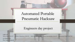
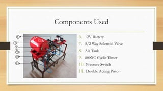
To understand the working of a pneumatic hacksaw and replicating a working prototype.
An Engineers day project for Christ University Faculty of Engineering, Bangalore.
Event name- ICE TECH 2017
Works on the principle of slider-crank mechanism with flywheel, motor and a pulley attached to it.
1. The machine can solve the problem of time consumption.
2. Waste of resources in face of labor cost is reduced.
3. The machine can be used in the industry where it is manufactured, at the packaging sector.
4. And it is used as hardware in large quantity like in fabrication of machine
5. It provide alternative for industries aiming toward reducing human effort
6. It generates sustainable and practical automation solutions for the future industrial development.
Importance of NC & CNC systems as a part of CAM by M.M.RAFIK.M.M. RAFIK
This document discusses numerical control (NC) and computer numerical control (CNC) machine tools. It defines NC as machine tools that are controlled by programmed symbols, numbers and letters to automate operations like spindle speed and tool positioning. CNC machine tools use a computer to perform basic NC functions and allow programming and storage of multiple parts. The document outlines the key elements, types, programming methods and advantages/disadvantages of both NC and CNC machine tools. It concludes by comparing NC and CNC and noting that CNC offers greater flexibility through online programming and editing capabilities.
The document discusses computer numerical control (CNC) machines. It begins by explaining the history of numerical control, which was developed in the 1950s and used coded instructions to automate machine tools. The development of electronics like microprocessors led to computer-based CNC systems with greater flexibility and precision. CNC machines are now used across many industries to automate machining processes. The document outlines the advantages of CNC machines like higher productivity, quality and accuracy compared to manual machine tools. It provides definitions of CNC and describes the typical components and closed-loop control systems used.
The document describes a project report submitted by three students - Suraj Maurya, Neel Shukla, and Nilesh Poojary - for their final year diploma in computer engineering on the topic of a "Mini CNC Plotter". It provides details of the project including an introduction, literature review, objectives, hardware and software requirements, hardware and software explanations, block diagrams, coding, testing procedures, working, applications, and conclusions. The report aims to provide complete information about designing and developing a mini computer numerical control (CNC) plotter.
This presentation summarizes the key characteristics of CNC machines. It describes how CNC machines are automated machine tools controlled by programmed commands stored on a computer. The history of CNC is outlined from its origins in the 1950s to become widely used today. The main types of CNC machines are identified as turning centers, milling centers, vertical machining centers, horizontal machining centers, drilling machines, EDM machines, and laser cutting machines. Programming codes like G-codes and M-codes are discussed as well as how CNC machines work through precise positioning coordinates.
This document discusses low cost automation techniques that can be used to improve productivity in manufacturing while requiring lower capital investments than more advanced automated systems. It introduces the concept of low cost automation as using simple pneumatic, hydraulic, mechanical, and electrical devices to automate existing production machinery. The document outlines several ways to achieve low cost automation, including through the use of mechanisms, pneumatics, electromechanical systems, electro-pneumatic systems, and hydro-pneumatic presses. The goal of low cost automation is to increase productivity and quality while reducing costs and labor needs.
This document describes the design of an automatic hacksaw machine. It contains sections on the working principle, power transmission using V-belts, a list of components including an AC motor, ball bearings, flywheel and pulley, a mechanical analysis of torque and speed ratios, design specifications and materials, and a cost estimation. The machine is designed to reduce the time and labor costs of manual hacksawing by automating the reciprocating motion. It provides the advantages of being easy to use, automatic, able to maintain consistent cutting parameters, and economical compared to manual labor. Limitations include an inability to cut larger diameters or be used for mass production.
The document discusses computer numerical control (CNC), direct numerical control (DNC), and adaptive control systems. It describes how CNC replaced conventional NC by using a computer to store machining programs instead of punched tapes. DNC connects multiple CNC machines to a central computer to facilitate programming and data collection. Adaptive control systems measure output variables during machining and dynamically adjust speeds/feeds to optimize performance based on variability in workpieces and tools.
DNC is a manufacturing system where a central computer controls a number of NC machines in real time through direct connections. The central computer is connected to machine tools and bulk memory for storing NC part programs. It can transmit programs on demand to machines and allows two-way real-time communication and program editing between the computer and machine tools. There are two systems for linking the computer and machines: behind-the-tape-reader and a special machine control unit.
This document discusses automated guided vehicles (AGVs) which are programmed to move materials between workstations on a factory floor. It describes the components, classifications, navigation methods, and control systems of AGVs. It also provides two case studies, one on developing an AGV to change sprinklers in irrigation and another on implementing an AGV system to transport goods in a hospital. The document aims to provide an overview of AGVs, their applications, and examples of their use.
This document describes a project report submitted for the degree of Bachelor of Engineering in Mechanical Engineering. The project involves the design and fabrication of a crankshaft-operated double hacksaw machine. The report includes an introduction outlining the objectives and justification of the project. It also provides a literature review on hacksaw machines and the types of hacksawing. The report then discusses the project methodology, components used, and working of the machine. It concludes with the results, discussion, and scope for future work. The overall aim is to develop an automated hacksaw machine that can cut multiple pieces simultaneously to improve productivity.
1. Numerical control (NC) systems were developed to automate machine tools using programmed sequences of instructions to control machine motions and functions.
2. NC systems use a machine control unit to read numerical input from a program and translate it into mechanical motions of the machine tool.
3. Modern computer numerical control (CNC) systems provide even greater flexibility and precision by using computers to generate and process NC programs and control machine tools.
The presentation discusses a 5-speed gearbox mechanism. It begins by providing background on the history of multi-speed gearboxes, noting that 5-speed transmissions became widespread in the 1980s. It then describes the main components and gearing arrangements in a 5-speed manual transmission. Finally, it explains an automated manual transmission (AMT) system and its advantages over a traditional manual transmission.
This document describes the components and workings of a pneumatic sheet cutting machine. The key components are a pneumatic cylinder, 5/2 direction control foot valve, shearing blade, frame, and air circulating devices. The pneumatic cylinder uses compressed air to move the piston rod and shearing blade in two directions. The 5/2 direction control foot valve controls the direction of air flow to move the cylinder in forward and reverse. Compressed air is stored in an air receiver and distributed through piping to power the cylinder while minimizing pressure drops.
This document provides an introduction to CAD/CAM (Computer Aided Design and Computer Aided Manufacturing). It defines CAD as using computers in the design process and CAM as using computers to plan, manage and control manufacturing operations. CAD/CAM systems support both the design process from conceptualization to documentation, and the manufacturing process from process planning to inspection. The implementation of CAD and CAM tools in an engineering environment can improve flexibility, reduce costs and lead times, and increase productivity, quality and customer service.
*Discretization of a Structure, 1D, 2D and 3D element Meshing, * Element selection criteria, *Refining Mesh,
*Effect of mesh density in critical region,
*Use of Symmetry.
*Element Quality Criterion:-Jacobian, Aspect ratio, Warpage, Minimum and Maximum angles, Average element size, Minimum Length, skewness, Tetra Collapse etc., *Higher Order Element vs Mesh Refinement,
*Geometry Associate Mesh, *Mesh quality,
*Bolted and welded joints representation,
*Mesh independent test.
Fundamentals of CAD/ CAM, Application of computers for Design and Manufacturing, Benefits of CAD/ CAM - Computer peripherals for CAD/ CAM, Design workstation, Graphic terminal, CAD/ CAM software- definition of system software and application software, CAD/ CAM database and structure. Geometric Modeling
Advantages & Limitations of CNC machine tools,Introduction DNC,Component of a DNC system,Principle,Functions of DNC
Types of DNC systems,Comparison between NC, CNC and DNC machine tools
Non-traditional machining techniques remove material using various energy sources besides traditional cutting tools. They are divided into mechanical, electrical, thermal, and chemical techniques. Non-traditional techniques are needed for hard or complex materials, and can machine intricate shapes and deep holes. Selection depends on the part geometry, material properties, machining capabilities, and cost effectiveness. While more expensive initially than traditional techniques, non-traditional machining offers higher precision, surface finish, and ability to machine difficult materials.
shaping, milling and gear cutting machineslaxtwinsme
Shaper – Types of operations. Drilling, reaming, boring, Tapping. Milling operations-types of milling cutter. Gear cutting – forming and generation principle and construction of gear milling ,hobbing and gear shaping processes –finishing of gears.
This document provides information on numerical control (NC) and computer numerical control (CNC) programming. It defines NC as using punched paper tape to control machine tools, while CNC uses a computer and software. The key components of an NC program are described as the part program, coded numbers specifying tool positions, and sequencing positions to machine parts. Advantages of CNC include easier programming, error correction, and increased flexibility compared to NC. Common G-codes and M-codes for controlling axes movement, circular interpolation, cutting parameters, and auxiliary functions are also outlined.
Course Objectives:
Students undergoing this course would
Understand different methods of 3D Printing.
Gain knowledge about simulation of FDM process
Estimate time and material required for manufacturing a 3D component
Course Outcomes:
Upon the successful completion of course, students will be able to
Explain different types of 3d Printing techniques
Identify parameters for powder binding and jetting process
Determine effective use of ABS material for 3D Printing
Apply principles of mathematics to evaluate the volume of material require.
Module 1:
Introduction to Prototyping, Working of 3D Printer, Types of 3D printing Machines:
Exp 1: Modelling of Engineering component and conversion of STL format.
Exp 2: Slicing of STL file and study of effect of process parameter like layer thickness,
Orientation and infill on build time using software.
Exercise 1 : Component-1
Exercise 2 : Component-2
Module 2:
Exp 1 : 3D Printing of modeled component by varying layer thickness.
Exp 2 : 3D Printing of modeled component by varying orientation.
Exp 3: 3D Printing of modeled component by varying infill.
Module 3:
Study on effect of different materials like ABS, PLA, Resin etc, and dimensional accuracy.
Module 4:
Identifying the defects in 3D Printed components.
Module 5
Exp1: Modelling of component using 3D Scanner of real life object of unknown dimension
in reverse engineering.
Exp 2: 3D Printing of above modeled component.
This document provides an overview of CNC machines. It discusses that CNC machines use a computer to convert a design into numerical codes that control machine tools to precisely shape materials. The history of CNC machines is explored, from early numerically controlled machines to modern CNCs linked directly to computers. Key parts of CNC machines are described along with their advantages in automating production, improving quality and accuracy, and manufacturing complex designs. Applications and some safety considerations are also summarized.
This document discusses different layout configurations for flexible manufacturing systems (FMS). It describes five types of FMS layouts: progressive or line type, loop type, ladder type, open field type, and robot centered type. For each type, it provides a brief explanation of the layout and flow of parts. It also lists some factors that influence the selection of an FMS layout, such as availability of materials and labor, transportation infrastructure, and local business conditions.
This document provides definitions and principles related to locating and clamping in jigs and fixtures design. It defines a jig as a device that holds work and locates the tool path, and a fixture as a device that locates work on a machine table. It discusses locating principles like six point location and 3-2-1 principle. It also covers various locating and clamping devices like pins, buttons, V-locators, and different types of clamps. The document aims to provide fundamental guidelines for effective design of jigs and fixtures.
CNC machines are computer-controlled machine tools that can be programmed to automatically perform tasks like cutting, drilling, grinding, milling, turning, and others. Key elements of a CNC machine include inputs, machine control units, machine tools, drives, feedback devices, and displays. CNC machines are used across industries like aerospace, machinery, automotive, and more to manufacture complex parts for products with high accuracy. Some common applications of CNC machines include engine blocks, aircraft parts, electronic components, and molds.
The document provides an overview and examples of wheel multiple systems used for aircraft wheel assembly. Key features discussed include advanced torque control strategies for socket engagement and synchronization, precision rotary suspension, compact packaging, and customizable solutions. Example applications presented are for mounting aircraft wheels to landing gears by driving multiple nuts evenly spaced around bolt circles to specified torques. Benefits outlined are improved accuracy, productivity, and ergonomics over manual assembly.
Automation for Horizontal Plastic Injection Moulding industries at to pick and place sprue (plastic waste) from plastic IMM to granulator within 8 sec reducing cycle time and thus enhancing productivity.Robot works on electro-pneumatic circuit operated by C programmed micro-controller.Design was validated in CATIA V5. The model works on 2 to 4 bar pressure air compressor with flow controlled.The model was designed for 40 to 65 ton machines. Different existing models were studied, industrial survey of 14 companies was done and by design synthesis, swing arm horizontal prototype was made with 1/2 kg payload for sprue.The robust mild steel body had miter bevel gear for power transmission and Teflon slider on aluminium arm.
The best design innovation was that through gravity use, gripper wrist rotation and vertical descend stroke for sprue release was eliminated in motion sequence by adopting swing arm horizontal robot configuration instead of conventional swing arm vertical movement. Also, effective trajectory planning for swing arm cylinder was done.
IRJET- Review Paper on Stirrup Making MachineIRJET Journal
This document summarizes several research papers on machines for making stirrups. It describes machines that use hydraulic, pneumatic or human power to bend rebar into stirrup shapes. Hydraulic machines can make multiple stirrups at once using hydraulic cylinders for bending and an indexing mechanism. Pneumatic machines use compressed air and pneumatic cylinders to bend the rebar through a series of strokes. One machine is powered by a human-powered flywheel to store energy for the bending process. Overall the document reviews different automated methods for stirrup making that aim to increase productivity over manual methods while reducing labor costs and worker fatigue.
The document summarizes a student project to design and fabricate a pneumatic sheet cutting machine. It includes components like a pneumatic cylinder, directional control valve, flow control valve, and cutting tool. The aim is to develop an effortless machine for small sheet metal cutting tasks. It will provide benefits like lower costs, higher accuracy, and not requiring skilled labor compared to existing manual methods. The design and working of the machine are explained along with a circuit diagram and cost analysis. Research on pneumatic valves is also reviewed from other literature.
This document is a project report on a pneumatic shaper machine. It contains an abstract, table of contents, and begins discussing pneumatic systems and their advantages like high effectiveness, durability, safety, and cost-effectiveness. It describes how pneumatic power will be used in this shaper machine instead of a crank and link mechanism to provide reciprocating motion. The report will continue analyzing components of pneumatic systems like compressors, cylinders, and control valves. It will also discuss the applications and limitations of pneumatic actuation.
This document is a project report on the manufacturing of a hydraulic robotic arm. It was submitted by Bijoy Mondal to fulfill the requirements for a diploma in mechanical engineering from Elitte Institute of Engineering and Management. The report details the components of the robotic arm including hydraulic cylinders, fluid lines, arms, grippers, a chassis, motor, and wheels. It also discusses the principles of hydraulic systems, classification of hydraulic robots, materials used, and the advantages and disadvantages of the design.
The document describes the design of an automatic pneumatic internal pipe scrap removing machine. It uses compressed air to power a pneumatic cylinder with a round file attached, which is used to remove scraps from the inside of pipes. The machine aims to increase efficiency and accuracy by reducing human involvement in the scrap removal process. It works by using compressed air to power the forward and backward stroke of the cylinder and file, which removes pipe scraps automatically. This provides a faster, more consistent method of internal pipe scrap removal compared to manual methods.
IRJET- Development of Ejection System to Improve ProductivityIRJET Journal
This document describes a project to improve the ejection system of an injection molding machine to increase productivity. The existing system uses two ejectors but takes a long time (80 seconds) per cycle. The proposed new system adds two additional ejectors on the front corners. This allows the molded component to be ejected with only one stroke, reducing the cycle time to 54 seconds. Calculations show the production rate increased by 48% with the modified system. Benefits include balanced ejection, eliminating component catching issues, and improved part quality. The objectives are to reduce ejection time, cycle time, and improve production rate and efficiency.
IRJET- Development of Ejection System to Improve ProductivityIRJET Journal
This document describes a project to improve the ejection system of an injection molding machine to increase productivity. The current machine uses two ejectors but it takes a long time and worker effort to remove molded components from the mold. The project aims to add two additional ejectors positioned at the corners of the ejector plate so that only one stroke is needed to eject components. This is expected to reduce ejection time, cycle time, and worker effort, while increasing production rates and part quality. The document provides background on injection molding and discusses the methodology and literature review conducted to support modifying the ejection system.
IJERD (www.ijerd.com) International Journal of Engineering Research and Devel...IJERD Editor
This document summarizes an article that describes automating a milling machine using an electro-pneumatic system. Milling is a common metal cutting process where a rotating cutting tool removes material. The article discusses automating the milling process using pneumatic devices like cylinders, valves, and sensors combined with electrical components like relays and switches. It provides an overview of milling machines and their components. It also discusses the general concepts of designing and developing pneumatic control systems, including functional diagrams, circuit diagrams, and documentation. Finally, it analyzes the costs of manual versus automated milling machines and their production times.
Fabrication of automatic hydraulic bending and bend removing machineIRJET Journal
This document describes the design and fabrication of an automatic hydraulic bending and bend removing machine. The machine uses hydraulics to bend and remove bends from pipes and rods. It consists of a hydraulic jack, die holders, pulley, slider, wiper motor and battery. Pipes are placed in die holders which are bent by the hydraulic jack when activated by the wiper motor and battery power. Bends can be removed by changing the die to a rectangular one. The machine allows for automated and precise bending and removing of bends in an economical manner compared to conventional methods. It has applications in production industries and automotive workshops.
This document describes an e-cycle garbage collector created by three students. It has two main parts: 1) an e-cycle powered by batteries and a hub motor for transportation. 2) A garbage collector attached for cleaning and waste collection. The garbage collector uses a suction motor and filters to collect and store garbage. It has features like variable speed control, a portable collection chamber, and indicators for battery and garbage storage levels. The document provides technical specifications, diagrams of the system design, and highlights how it provides an eco-friendly electric alternative for cleaning and transport.
The document discusses the design of a pneumatic robot for costic recovery in a textile factory. It outlines several objectives for the project, including designing each component mathematically and determining stress analysis. It also discusses limitations like a lack of internet access and cost constraints. Several chapters analyze the design concepts, including two models - one powered by an engine and the other by an electric motor. Design considerations like material selection, working mechanisms, and input parameters are evaluated. Specific component designs are analyzed, such as the column support, shaft, and connecting base and colemun. The document provides details on the problem, objectives, methodology, conceptual designs, and structural analysis of key parts for the pneumatic robot.
This document provides an overview and specifications for the Acrab series lead-free wave soldering machine produced by ETA. It describes the machine's features such as its nozzle, spray control system, cleaning device, temperature protection and control, heating module, conveyor system, spray system, preheating system, soldering system, cooling system and optional configurations. Specifications for dimensions, weight, power requirements, conveyor details and soldering capabilities of the Acrab350 and Acrab450 models are also provided.
Modeling & Thermal Analysis of Radial EngineIRJET Journal
The document describes modeling and thermal analysis of a radial engine. It discusses modeling the main components of the radial engine like the articulated rod, piston, master rod, piston link, etc. in ANSYS. It then describes assembling the components and performing a transient thermal analysis in ANSYS to determine temperatures and thermal stresses over time. The analysis results for components like the piston, master rod, inlet valve, and radial connecting rod made of different materials under varying thermal loads are presented.
Utilization of plc programming for gravity die casting automationeSAT Journals
The document describes utilizing a programmable logic controller to automate a gravity die casting process through PLC programming in order to increase productivity and reduce costs. It details the functional cycle and components used, including pneumatic cylinders, grippers, and a rotary actuator controlled by the PLC. Calculations are provided to determine the cylinder dimensions and cycle time needed for each step of the automated casting process.
The Pneumatics is study of mechanical motion caused by pressurized gases and how this motion can be used to perform engineering tasks.
Pneumatic systems operate on a supply of compressed air which must be available in sufficient quantity and the air used in pneumatic devices is dried and free from moisture so that it does not create any problem to the internal parts of the system and avoid corrosive actions too.
The compressed air is delivered by the compressor which is a machine that takes in air or gas at a certain pressure and delivered the air at a high pressure.
This machine is pneumatic powered machine and electrical energy is used to operate which has low co-efficient of friction and air.
This machine is designed in solid-works software (module 2017).
Similar to Portable Automatic Pneumatic hacksaw (20)
A SYSTEMATIC RISK ASSESSMENT APPROACH FOR SECURING THE SMART IRRIGATION SYSTEMSIJNSA Journal
The smart irrigation system represents an innovative approach to optimize water usage in agricultural and landscaping practices. The integration of cutting-edge technologies, including sensors, actuators, and data analysis, empowers this system to provide accurate monitoring and control of irrigation processes by leveraging real-time environmental conditions. The main objective of a smart irrigation system is to optimize water efficiency, minimize expenses, and foster the adoption of sustainable water management methods. This paper conducts a systematic risk assessment by exploring the key components/assets and their functionalities in the smart irrigation system. The crucial role of sensors in gathering data on soil moisture, weather patterns, and plant well-being is emphasized in this system. These sensors enable intelligent decision-making in irrigation scheduling and water distribution, leading to enhanced water efficiency and sustainable water management practices. Actuators enable automated control of irrigation devices, ensuring precise and targeted water delivery to plants. Additionally, the paper addresses the potential threat and vulnerabilities associated with smart irrigation systems. It discusses limitations of the system, such as power constraints and computational capabilities, and calculates the potential security risks. The paper suggests possible risk treatment methods for effective secure system operation. In conclusion, the paper emphasizes the significant benefits of implementing smart irrigation systems, including improved water conservation, increased crop yield, and reduced environmental impact. Additionally, based on the security analysis conducted, the paper recommends the implementation of countermeasures and security approaches to address vulnerabilities and ensure the integrity and reliability of the system. By incorporating these measures, smart irrigation technology can revolutionize water management practices in agriculture, promoting sustainability, resource efficiency, and safeguarding against potential security threats.
Presentation of IEEE Slovenia CIS (Computational Intelligence Society) Chapte...University of Maribor
Slides from talk presenting:
Aleš Zamuda: Presentation of IEEE Slovenia CIS (Computational Intelligence Society) Chapter and Networking.
Presentation at IcETRAN 2024 session:
"Inter-Society Networking Panel GRSS/MTT-S/CIS
Panel Session: Promoting Connection and Cooperation"
IEEE Slovenia GRSS
IEEE Serbia and Montenegro MTT-S
IEEE Slovenia CIS
11TH INTERNATIONAL CONFERENCE ON ELECTRICAL, ELECTRONIC AND COMPUTING ENGINEERING
3-6 June 2024, Niš, Serbia
KuberTENes Birthday Bash Guadalajara - K8sGPT first impressionsVictor Morales
K8sGPT is a tool that analyzes and diagnoses Kubernetes clusters. This presentation was used to share the requirements and dependencies to deploy K8sGPT in a local environment.
Harnessing WebAssembly for Real-time Stateless Streaming PipelinesChristina Lin
Traditionally, dealing with real-time data pipelines has involved significant overhead, even for straightforward tasks like data transformation or masking. However, in this talk, we’ll venture into the dynamic realm of WebAssembly (WASM) and discover how it can revolutionize the creation of stateless streaming pipelines within a Kafka (Redpanda) broker. These pipelines are adept at managing low-latency, high-data-volume scenarios.
Using recycled concrete aggregates (RCA) for pavements is crucial to achieving sustainability. Implementing RCA for new pavement can minimize carbon footprint, conserve natural resources, reduce harmful emissions, and lower life cycle costs. Compared to natural aggregate (NA), RCA pavement has fewer comprehensive studies and sustainability assessments.
Embedded machine learning-based road conditions and driving behavior monitoringIJECEIAES
Car accident rates have increased in recent years, resulting in losses in human lives, properties, and other financial costs. An embedded machine learning-based system is developed to address this critical issue. The system can monitor road conditions, detect driving patterns, and identify aggressive driving behaviors. The system is based on neural networks trained on a comprehensive dataset of driving events, driving styles, and road conditions. The system effectively detects potential risks and helps mitigate the frequency and impact of accidents. The primary goal is to ensure the safety of drivers and vehicles. Collecting data involved gathering information on three key road events: normal street and normal drive, speed bumps, circular yellow speed bumps, and three aggressive driving actions: sudden start, sudden stop, and sudden entry. The gathered data is processed and analyzed using a machine learning system designed for limited power and memory devices. The developed system resulted in 91.9% accuracy, 93.6% precision, and 92% recall. The achieved inference time on an Arduino Nano 33 BLE Sense with a 32-bit CPU running at 64 MHz is 34 ms and requires 2.6 kB peak RAM and 139.9 kB program flash memory, making it suitable for resource-constrained embedded systems.
Advanced control scheme of doubly fed induction generator for wind turbine us...IJECEIAES
This paper describes a speed control device for generating electrical energy on an electricity network based on the doubly fed induction generator (DFIG) used for wind power conversion systems. At first, a double-fed induction generator model was constructed. A control law is formulated to govern the flow of energy between the stator of a DFIG and the energy network using three types of controllers: proportional integral (PI), sliding mode controller (SMC) and second order sliding mode controller (SOSMC). Their different results in terms of power reference tracking, reaction to unexpected speed fluctuations, sensitivity to perturbations, and resilience against machine parameter alterations are compared. MATLAB/Simulink was used to conduct the simulations for the preceding study. Multiple simulations have shown very satisfying results, and the investigations demonstrate the efficacy and power-enhancing capabilities of the suggested control system.
We have compiled the most important slides from each speaker's presentation. This year’s compilation, available for free, captures the key insights and contributions shared during the DfMAy 2024 conference.
ACEP Magazine edition 4th launched on 05.06.2024Rahul
This document provides information about the third edition of the magazine "Sthapatya" published by the Association of Civil Engineers (Practicing) Aurangabad. It includes messages from current and past presidents of ACEP, memories and photos from past ACEP events, information on life time achievement awards given by ACEP, and a technical article on concrete maintenance, repairs and strengthening. The document highlights activities of ACEP and provides a technical educational article for members.
Electric vehicle and photovoltaic advanced roles in enhancing the financial p...IJECEIAES
Climate change's impact on the planet forced the United Nations and governments to promote green energies and electric transportation. The deployments of photovoltaic (PV) and electric vehicle (EV) systems gained stronger momentum due to their numerous advantages over fossil fuel types. The advantages go beyond sustainability to reach financial support and stability. The work in this paper introduces the hybrid system between PV and EV to support industrial and commercial plants. This paper covers the theoretical framework of the proposed hybrid system including the required equation to complete the cost analysis when PV and EV are present. In addition, the proposed design diagram which sets the priorities and requirements of the system is presented. The proposed approach allows setup to advance their power stability, especially during power outages. The presented information supports researchers and plant owners to complete the necessary analysis while promoting the deployment of clean energy. The result of a case study that represents a dairy milk farmer supports the theoretical works and highlights its advanced benefits to existing plants. The short return on investment of the proposed approach supports the paper's novelty approach for the sustainable electrical system. In addition, the proposed system allows for an isolated power setup without the need for a transmission line which enhances the safety of the electrical network
1. Automated Portable
Pneumatic Hacksaw
Engineers day project
GROUP:
Shibin Babu 1661451 , Philbert Mendonca 1661441 , Akhil Harold 1661402 , Andre Mascarenhas 1661407 , Mohammed Akhil 1661516
GUIDED BY:
Prof. Sajna Panigrahi
2. Contents
Sl. No. TOPIC No. of Slides
1 Why do we need an Automated hacksaw? 1
2 How does it work? 1
3 Components Used 2
4 Comparison (with manual cutting) 1
5 Future work on Project 1
3. Why do we need an Automated hacksaw?
• Reduces the production time with higher production volume.
• Increased safety as there is no need to deal with the blade manually.
• Reduced human error
• Decreased labor cost and number of laborers.
• Pneumatic system is a cheaper, safer and a more flexible alternative to
electric motors and actuators.
4. How does it work?
Battery
800XC
Timer
Air Tank
Pressure
Switch
Compressor
(5/2 Solenoid valve)
(Double acting
Pneumatic
Cylinder)
5. Components Used
1. Air Compressor -10 bar
2. Linear motion bearings with C45
Alloy guideways
3. Hacksaw frame with HCC blade
4. Bench Vise
5. Screw Jack
0
1
1
1
1
2
3
4
5
1
6. Components Used
6. 12V Battery
7. 5/2 Way Solenoid Valve
8. Air Tank
9. 800XC Cyclic Timer
10. Pressure Switch
11. Double Acting Piston
6
7
18
19
10
11
7. Comparison
Material Manual Hacksaw cutting Automated Hacksaw
Al(5mm) 42.16 30.56
Al (25mm) 172.42 160.34
Nylon (12mm) 11.28 8.02
Hollow Mild steel (1mm) 78.42 65.11
Time (in seconds)
8. Future Work on Project
• Use Rectifier to take power from AC source instead of a battery.
• Fully automate the project using Arduino programming.
• Use stepper motor to rise workpiece on vise.
• Use a FSR sensor to activate stepper motor.
• Take input through keypad and display with LCD screen.
• Given input determines how much the machine should cut of the work piece
in centimeter and millimeter.