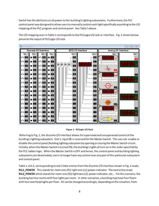
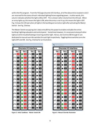
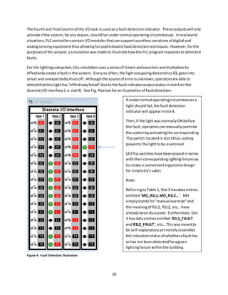
The document describes a PLC program for controlling various subsystems in a building, including lighting, HVAC, access/security, communications, and fire safety/water/plumbing. It provides details on how a PLC could be programmed using ladder logic to control a lighting subsystem with 16 lights over 4 rooms. The PLC program includes a master switch input to enable or disable control of the lighting subsystem. It also allows individual manual control of each light and monitoring of their power status. Tables and figures illustrate the PLC I/O mapping and interface. Similar PLC programs are described for other subsystems.
![4
I. Introduction
A. Smart Buildings
Everysmart buildinghasacontrol room, especiallybuildingslike airports,hospitals,prisonsandpower
plants. These control roomsallowoperatorstomonitorandmanage subsystems remotelyand
sometimesautomatically. Subsystemslike energy,water, plumbing,HVAC,lighting,fire safety,access
and security,elevators,communication,robotsandpower equipmentall requirespecialattention,
because failure in anyone of these subsystemscouldspell disasterunderthe wrongsetof
circumstances. Althougheachsubsystemhasvariable importance,failureisintolerable because
somethingassimple as waterunexpectedly shuttingoff inabuildingcanhave consequencesranging
fromminordiscomforttonuclearmeltdown. The importance of eachsubsystemisentirelydependent
on the type of critical infrastructure that isbeingsupporting.
B. Critical Infrastructure
Critical infrastructurereferstothe infrastructure whoseassets,systemsandnetworks are consideredso
importantto the UnitedStates thattheirdysfunction would bringforthdire consequences fornational
economicsecurity aswell as national publicsafetyorhealth concerns[1]. Accordingtothe United
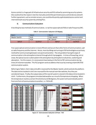
StatesDepartmentof HomelandSecurity,there are 16 differentcritical infrastructuresincludingthe
following:
Nearlyall of the sectorslistedhere,aside fromtransportationsystems,relymostlyonbuildingsor
superstructuresforshelter. Hence,the subsystems comprisingnearly100% of all critical infrastructures
inthe UnitedStatesare subsystemsrelatedtocommercial andindustrial buildings. Formore oncritical
infrastructures,referto[1].
C. SubsystemOverview
Withoutthe implementationof automationandcontrol systemssome of the subsystemstalkedabout
previously are prone tocatastrophicfailure. The followingsection providesinsighttohow each
subsystemcanbe improvedbyimplementingautomationandcontrols. Furthermore,some sections
provide acomparisonbetweensystemshavingautomationandcontrols tosystemslackingautomation
and controls. Here isa listof the subsystems previousmentioned:
Dams
Defense industrial bases
Emergencyservicessector
Energysector
Informationtechnologysectors
Nuclearreactors,materialsandwaste
Transportationsystems sectors
Water andwastewatersystems
Financial servicessector
Foodand agriculture
Governmentfacilities sector
Healthcare andpublichealthsectors
Chemical sector
Commercial facilitiessector
Communicationssector
Critical manufacturingsector](https://image.slidesharecdn.com/28bad397-ee08-4a52-9cf3-900228233f39-160705230210/85/PLC-Building-Automation-and-Control-Systems-5-320.jpg)
![5
1. Access and Security
Since the year2013, there have beenover180 school shootings inthe UnitedStates;hence,accessand
securityisa top concernwhenitcomesto establishingsubsystemswithincritical infrastructure. A good
securitysystemhasbothactive andpassive sensorsusedforremote sensing. Furthermore,automated
alarmingsystems aswell asphysical barriershelpcontribute tothe overall effectivenessof the security
systeminplay. Whenhumansencounterdanger,ourfirstresponse isautomatic,i.e.eitherfightor
flight. Witha properautomationandcontrol system, accessand securitysubsystemsinbuildings may
be able to assistindeterringfuture school shootings,bankrobberies, terroristattacks orsimilaractsof
crime and terror.
2. CommunicationSystems
Aside fromaccessand security,abuilding’scommunication systemisatop subsystemconsideration
because communicationishalf of whatmakes abuildingsmart,the otherhalf beingautomationand
control. Integratingautomationandcontrol techniquesin communicationsystemswithinbuildings may
allowformore robustinternal andexternal formsof communication. Forexample,manual orautomatic
control of the methodsof communicationusedcouldincrease buildingenergyefficiencywhileenabling
a widerrange of possibilitieswhenitcomestointernal orexternal buildingcommunications.
Furthermore,implementingautomationandcontrolsin communicationsystems couldhelp technicians
or buildingoccupantstroubleshootthe systemsduringtimesof unexpectedfailure. Thistopicis
discussedinfurtherdetail inthe PLCsolutioncase study. See Ref [2] or the ZigBee Alliance/BACnet.
3. Elevators and Escalators
Althoughthissubsystemhasnorelevance in singlestorybuildings,itisalmostalwaysreasonforconcern
inbuildingsof twoormore stories. Hospitals,schools,banks,mallsandlibrariesall have elevators or
escalators toaccommodate those who are handicappedorthose whohave beendisabledinsome way
shape or form. Elevatorsor escalatorswithoutautomationorcontrol systemsare notonlydangerous
but alsowasteful inregardstopower andenergy consumption. Inthe case that one or more floors
withinabuildingare onfire,allowingthese systemstoremainoperational isnotonlystupidbutit could
leadto unnecessary lossof life. Furthermore, leavingescalatorsoncontinuously isaproblemdue tothe
fact that cost will goup, energyefficiency will godownand emergency responseorroutine maintenance
will become negligible.
4. Fire Safety
Anotherimportantsubsystem,thatwhichprotectsthe building’sinhabitants,isthe fire safetysystem.
Withoutautomationandcontrol,response toanemergencysituationsuchasa fire wouldbe much
slowerthanif there were sensorsandautomaticproceduresinvolved. Peoplewouldhave torunaround
tryingto findthe fire extinguisherthenrunall the wayback to the fire,whichhasspreaduncontrollably
by that point. Implementingautomationandcontrol featurestoalreadyexistingfire safetysystems
couldnot onlyreactinstantlytofire;moreover,manual operationsof the fire safetysystemcomponents
like the waterlinescouldpreventwastedwaterincasesof false alarm.](https://image.slidesharecdn.com/28bad397-ee08-4a52-9cf3-900228233f39-160705230210/85/PLC-Building-Automation-and-Control-Systems-6-320.jpg)
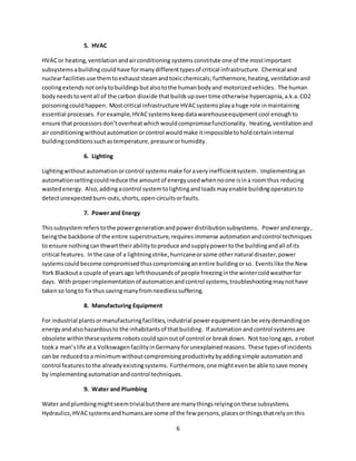
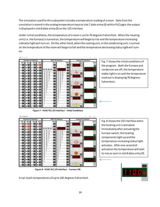
![12
Motor_2 is the exhaustfanmotor,solelyresponsibleforventingthe fumesaccumulatedinthe
combustionchamber. Valve_1isthe gasvalve andis responsible forsupplyingthe furnace burnerswith
fuel forcombustion. See Fig.5belowfora visual representationof a typical heatingunit.
Figure 5: Gas Powered Heating Unit Ref. [2]](https://image.slidesharecdn.com/28bad397-ee08-4a52-9cf3-900228233f39-160705230210/85/PLC-Building-Automation-and-Control-Systems-13-320.jpg)
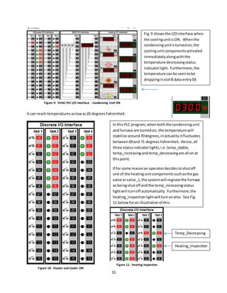
![13
The secondinitial input,i.e.the condensingunit,isresponsibleforcoolingthe building. When
Condensing_Unitisclosed,the coolingcomponentsactivate,i.e.Motor_3,Motor_4, Valve_2and
Valve_3. Motor_3 isresponsibleforthe condensingunitfanmotor,Motor_4 isthe compressorpump
motor,Valve_3and Valve_4are the suctionline andliquidline valves. Valves3and 4 are essentiallythe
twovalvesassociatedwiththe coolantlines. See Fig.6below forthe anatomyof a condensingunit.
Slots1 and2 correspondtothe heatingandcoolingunitsandtheirconstituentcomponents
respectively. Slot3 isusedfor controllingeachof the individual componentswithinthe heatingor
coolingunits. Switches1through7 can be manuallytriggeredtocutoff orrestore powertoone of the
componentsinsuch casesas the motor. For valves,these switcheswill eitheropenorclose a valve with
directinstruction.
Slot4 isdedicatedtothe systemstatusindicators,i.e.the temperature rising,temperaturefallingand
temperature stable statuses. Eachstatus isdiscernedbya lightturningon. Furthermore,there isthe
heatinginspectionstatuswhichmeansone of the heatingunitswitcheshave beenflippedandthere is
the coolinginspectionstatuswhichindicatesthata coolingunitswitchhasbeenflipped, mostlikelyfor
inspectionpurposes. See Table 2above forthe complete I/Omap.
Figure 6: Condensing Cooling Unit Ref. [3]](https://image.slidesharecdn.com/28bad397-ee08-4a52-9cf3-900228233f39-160705230210/85/PLC-Building-Automation-and-Control-Systems-14-320.jpg)
![17
C. Access and SecuritySubsystems
There are twodifferenttypesof securitytechniques,i.e.perimetercontrol andinternal breach.
Perimetercontrol isamethodusedtokeepintruders/perpetratorsoutof the safetyarea,whereas
internal breachsecurityisusedwhenthe intruder/perpetratorhasbreachedthe premises.
Differenttypesof critical infrastructure require differentlevelsof security. Forexample,anairport
requiresmore securitythaneducationalfacilitiesbecause theyare subjecttomore damagesif
perpetrated. Eventhoughitisdifficulttoharborthe truth that casinoshave greatersecuritycounter
measuresthanlocal highschoolsorelementary schools;realityis,statisticssaythatpremiseslike banks,
casinos,airports,prisons,powerplants,etcetera;all require higherstandards andoftentimes harbor
incrediblyexpensive securitysystems toprotecttheirassets;soexpensive that mosteducational
facilitiesare unable toaffordsuchcountermeasures.
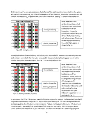
Althoughschoolsare unlikelytoaffordgreatbigsecuritysystems,theycanaffordsome of the basicsas
to preventperimeterbreachesduringafterhours. All securitysystemsbigorsmall runonsome type of
PLC or microcontrolleralongwith24hour supervision. Thissystemwill preventperpetratorsfrom
obtainingaccesstothe safetyareathrougha PLC access control programusingPLCLogix.
The simulationcreatedusingthe PLCLogix software emulatesanelectronickeypaddoorlock. This
device isusedtokeepunwantedsuspectslackingauthorityornecessarycredentialsoutof a designated
area. For example,agunmantryingto gainaccess to a school wouldbe deniedthe opportunity to
wreakhavoc due to the perimeter“accesscontrol”systeminplace. Thatiswhat thisprogramseeksto
do.
Figure 14: Electronic Keypad Lock Ref. [4]](https://image.slidesharecdn.com/28bad397-ee08-4a52-9cf3-900228233f39-160705230210/85/PLC-Building-Automation-and-Control-Systems-18-320.jpg)
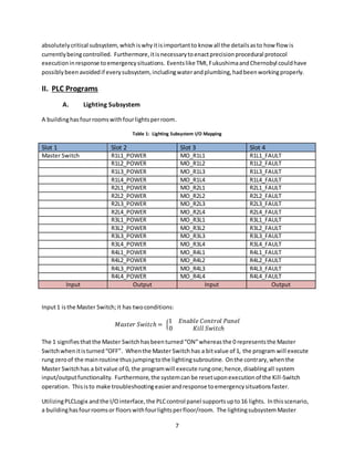
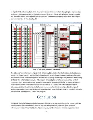
![22
Figures19 and 20 showthe twomaindevicesusedinfire safetysystemswithinbuildings. Fig.19 shows
the waterdispensingnozzle whichisresponsibleforthwartingactive firesandFig.20 showsan ionizing
fire detectorwhichisusedindetectingthe signsof anactive fire. These twodevicesworkinharmonyto
ensure buildingsafetyagainstthreatregardingfire safety. The PLCprogram forthisbuildingsubsystem
shouldallowfora more efficient approachtohandlingbuildingfires. Byallowingformore precise
control of the water,plumbingandfire safetysystem, the situationislesslikelytoresultinloss,i.e.loss
of water,resourcesandlife.
The simulationbuiltintothisprogramruns ona 60 secondtimerthat alternatesbetweentwoscenarios,
1) an ionizingfire detectordetectssmoke and2) an ionizingfiredetectordoesnotdetectsmoke. When
no smoke isdetected,the I/OmaplooksasshowninFig.21 below.
Figure 19: Water Dispersing Nozzle Ref. [5] Figure 10: Ionizing Fire Detector Ref. [6]
Figure 11: Fire Safety Subsystem I/O Rack](https://image.slidesharecdn.com/28bad397-ee08-4a52-9cf3-900228233f39-160705230210/85/PLC-Building-Automation-and-Control-Systems-23-320.jpg)

![25
References
[1] Critical Infrastructure Sectors
https://www.dhs.gov/critical-infrastructure-sectors
[2] Coolingunit
https://www.google.com/search?q=condenser+unit+anatomy&biw=1366&bih=705&source=lnms&tbm
=isch&sa=X&ved=0ahUKEwj-kd65j_vMAhWly4MKHW_fD4UQ_AUIBygB#imgrc=pl-hCZdwfG7tSM%3A
[3] Heatingunit
https://www.google.com/search?biw=1366&bih=705&tbm=isch&sa=1&q=furnace+anatomy&oq=furnac
e+ana&gs_l=img.3.0.0.188580.201657.0.203118.37.16.20.1.3.0.166.1904.1j15.16.0....0...1c.1.64.img..0.
37.2109...0i10j0i10i24.izOMcytuEiQ#imgrc=qZUHA4RAqXuCrM%3A
[4] AccessControl Keypad
https://www.google.com/search?q=keypad+door+lock&espv=2&source=lnms&tbm=isch&sa=X&ved=0a
hUKEwjfsdmEoJbNAhUEbD4KHQiFDM4Q_AUICSgC#imgrc=x_dz4OeLzSGfvM%3A
[5] Water DispersingNozzle
https://www.google.com/url?sa=i&rct=j&q=&esrc=s&source=images&cd=&cad=rja&uact=8&ved=0ahU
KEwjvxJv9maDNAhVS72MKHa_kD8gQjRwIBw&url=http%3A%2F%2Findore.all.biz%2Fwater-sprinkler-
system-g110729&psig=AFQjCNFLaQqW5ZLlNZLuhahhiDBRV7gKFg&ust=1465742318225508
[6] IonizingFire Detector
https://www.google.com/url?sa=i&rct=j&q=&esrc=s&source=images&cd=&cad=rja&uact=8&ved=0ahU
KEwjNke7Dm6DNAhVT1GMKHcDOCtsQjRwIBw&url=http%3A%2F%2Fwww.cableorganizer.com%2Fsmo
ke-detectors%2F&psig=AFQjCNFxjfliyPZSHFSaVHlxI1gWNKWavQ&ust=1465742780592482](https://image.slidesharecdn.com/28bad397-ee08-4a52-9cf3-900228233f39-160705230210/85/PLC-Building-Automation-and-Control-Systems-26-320.jpg)