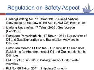
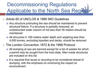
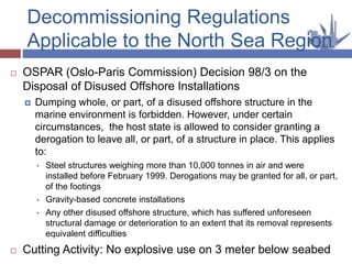
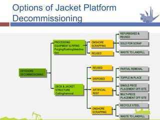
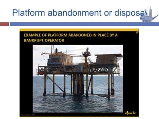
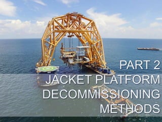
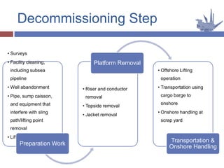
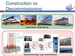
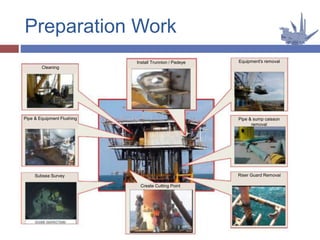
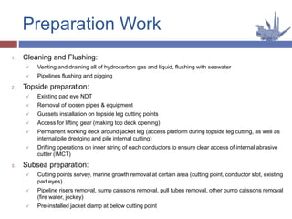
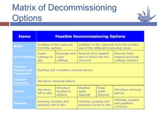
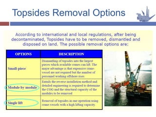
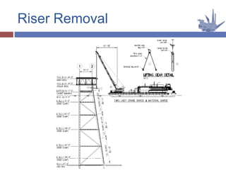
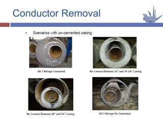
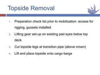
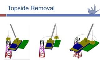
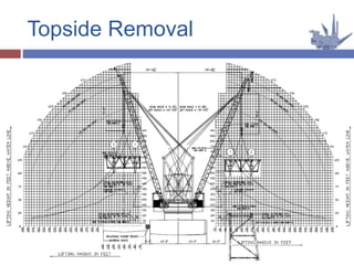
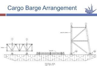
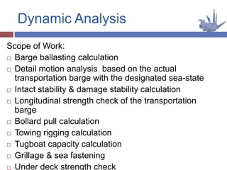
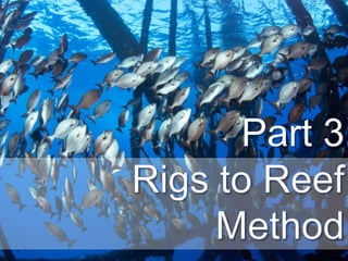
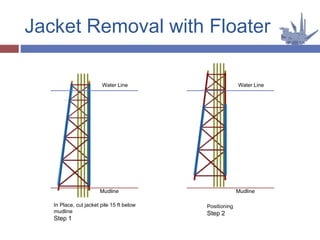
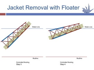
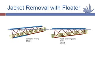
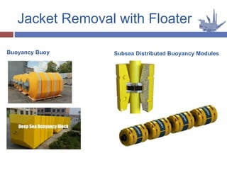
This document discusses various methods and considerations for decommissioning offshore platforms. It begins by outlining regulatory requirements for decommissioning from organizations like the UN and IMO. It then describes the different options for removing platform components like conductors, topsides, and jackets. Conductors can be removed using internal cutting or sectioning. Topsides are typically lifted off intact and transported by cargo barge. Jackets may be fully removed or left partially in place according to regulations. The document also discusses preparations needed like cleaning, surveys and installing lifting points. Transportation involves cargo barges, dynamic analysis, and onshore handling. Leaving platforms as artificial reefs is also evaluated. Overall, the document provides a comprehensive overview of offshore platform

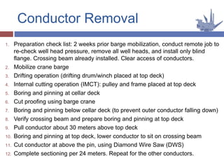
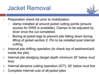


![[4] ptk 2014 2015 offshore constructions](https://cdn.slidesharecdn.com/ss_thumbnails/mhu59qizqiwfpndume0q-signature-e54dc48fc8dff231a3667ed370712382aa80c6605f7be8d156fba02fb451e6f5-poli-141027141817-conversion-gate01-thumbnail.jpg?width=640&height=640&fit=bounds)


