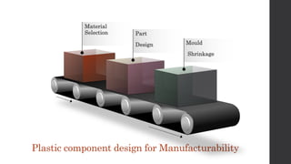
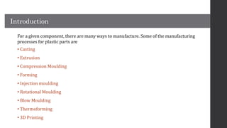
Material
Selection Part
Design Mould
Shrinkage
Plastic component design for Manufacturability
• Plastics component are prevalent in consumer and industrial segments for its strength
to weight ratio, low cost and ease of manufacturability.
• They have a clean surface finish, water and UV resistance, chemical resistance and
corrosion resistance.
• From bumpers in automotive, Computer Peripherals-Mice, keyboards, Medical equipment
for its sterility, mobile components, packaging products – plastic component has its
footprint.
Introduction
Introduction
For a given component, there are many ways to manufacture. Some of the manufacturing
processes for plastic parts are
• Casting
• Extrusion
• Compression Moulding
• Forming
• Injection moulding
• Rotational Moulding
• Blow Moulding
• Thermoforming
• 3D Printing
Material Selection:
• Polymer selection is always a tedious part in the product development phase.
Mostly, product engineers rely on the vendors to advise a suitable variant of
polymer for the product.
• Based on the objectives and requirements pledged by the product’s operation
and working environment – polymers are selected based on the level of
Chemical and UV resistance, Temperature, Heat resistance, Flammability,
Electrical and Mechanical capabilities, required surface finish and assembly
ease suitable material are chosen.
• Due to the day by day developments in polymer resins, the feasibility of
manufacturing process for the material, its availability and cost are taken into
account on selection.
Part Design:
Radius:
• Internal sharp edges have to be avoided while designing the component.
• All corners and edges are to be filleted and provided with the radius based on
the thickness considered and the strength parameters required near the
corners.
• As a general thumb rule, the corners and edges are filleted with a radius of 0.9
to 1.2 times the nominal thickness
Wall Thickness :
• Wall thickness is a primary element for the strength of the component and is
also in the prospect of manufacturability.
• Wall thickness has to be consistent to avoid most of the defects occurring during
the manufacturing processes. In-consistent thicknesses affect mould flow, part
formation and cooling.
• Higher thickness may affect the flow and cooling of the flow. Radius and
Rounded corners in the edges help proper filling in the mould.
Draft Angle:
• Taper in the vertical walls of the component is called the draft angle.
• Positive draft angle enables proper ejection of the component from the die
without damage.
• As a general thumb rule, the draft angle of 1 to 2 degrees is applied to the inner
vertical walls.
Gate Location
• Gates ensures proper resin flow and filling of the cavity in the mould.
• Gates are positioned to effectively fill the cavity in the mould before the resin
cools down.
• Type of gate and its position varies based on the geometric complexity and has a
high impact over the feasibility of producing the component without any
defects.
Ribs
• Plastic components with small wall thickness and requires mechanical strength
– Ribs are provided to reinforce the walls and to reduce shrinking.
• To eliminate white marks, 50 to 70 per cent of the wall thickness is considered
for ribs.
Mould Shrinkage:
• Generally, 20 per cent of the volume gets reduced from the cavity due to
shrinkage while cooling.
• Amorphous material shrinks lesser over crystalline polymers. Some of the
parameters to consider to avoid shrinkage are – Polymer formulation, mould
design, process temperature, melting temperature, cooling temperature,
injection speed, time and pressure.
Conclusion :
• Graphler Technology providing services like 3D to 2D Conversion Services,
• CAD Conversion Services etc.
• We have engineering experts specialized in CAD, FEA Services, Plastic Design,
Plastic Part design, Pressure Vessel Analysis Services, Surface modelling and on 3D
Modelling Services in India etc.

Plastic component design for manufacturability

  • 1.
    Material Selection Part Design Mould Shrinkage Plasticcomponent design for Manufacturability
  • 3.
    • Plastics componentare prevalent in consumer and industrial segments for its strength to weight ratio, low cost and ease of manufacturability. • They have a clean surface finish, water and UV resistance, chemical resistance and corrosion resistance. • From bumpers in automotive, Computer Peripherals-Mice, keyboards, Medical equipment for its sterility, mobile components, packaging products – plastic component has its footprint. Introduction
  • 4.
    Introduction For a givencomponent, there are many ways to manufacture. Some of the manufacturing processes for plastic parts are • Casting • Extrusion • Compression Moulding • Forming • Injection moulding • Rotational Moulding • Blow Moulding • Thermoforming • 3D Printing
  • 5.
    Material Selection: • Polymerselection is always a tedious part in the product development phase. Mostly, product engineers rely on the vendors to advise a suitable variant of polymer for the product. • Based on the objectives and requirements pledged by the product’s operation and working environment – polymers are selected based on the level of Chemical and UV resistance, Temperature, Heat resistance, Flammability, Electrical and Mechanical capabilities, required surface finish and assembly ease suitable material are chosen. • Due to the day by day developments in polymer resins, the feasibility of manufacturing process for the material, its availability and cost are taken into account on selection.
  • 6.
  • 7.
    Radius: • Internal sharpedges have to be avoided while designing the component. • All corners and edges are to be filleted and provided with the radius based on the thickness considered and the strength parameters required near the corners. • As a general thumb rule, the corners and edges are filleted with a radius of 0.9 to 1.2 times the nominal thickness
  • 8.
    Wall Thickness : •Wall thickness is a primary element for the strength of the component and is also in the prospect of manufacturability. • Wall thickness has to be consistent to avoid most of the defects occurring during the manufacturing processes. In-consistent thicknesses affect mould flow, part formation and cooling. • Higher thickness may affect the flow and cooling of the flow. Radius and Rounded corners in the edges help proper filling in the mould.
  • 9.
    Draft Angle: • Taperin the vertical walls of the component is called the draft angle. • Positive draft angle enables proper ejection of the component from the die without damage. • As a general thumb rule, the draft angle of 1 to 2 degrees is applied to the inner vertical walls.
  • 10.
    Gate Location • Gatesensures proper resin flow and filling of the cavity in the mould. • Gates are positioned to effectively fill the cavity in the mould before the resin cools down. • Type of gate and its position varies based on the geometric complexity and has a high impact over the feasibility of producing the component without any defects.
  • 11.
    Ribs • Plastic componentswith small wall thickness and requires mechanical strength – Ribs are provided to reinforce the walls and to reduce shrinking. • To eliminate white marks, 50 to 70 per cent of the wall thickness is considered for ribs.
  • 12.
    Mould Shrinkage: • Generally,20 per cent of the volume gets reduced from the cavity due to shrinkage while cooling. • Amorphous material shrinks lesser over crystalline polymers. Some of the parameters to consider to avoid shrinkage are – Polymer formulation, mould design, process temperature, melting temperature, cooling temperature, injection speed, time and pressure.
  • 13.
    Conclusion : • GraphlerTechnology providing services like 3D to 2D Conversion Services, • CAD Conversion Services etc. • We have engineering experts specialized in CAD, FEA Services, Plastic Design, Plastic Part design, Pressure Vessel Analysis Services, Surface modelling and on 3D Modelling Services in India etc.