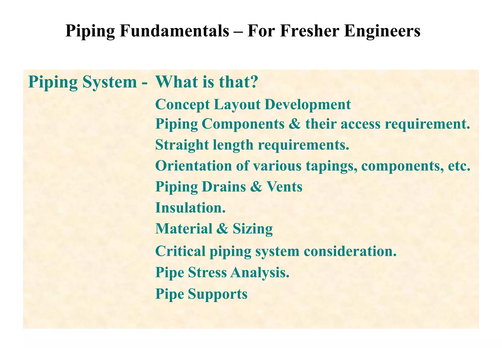
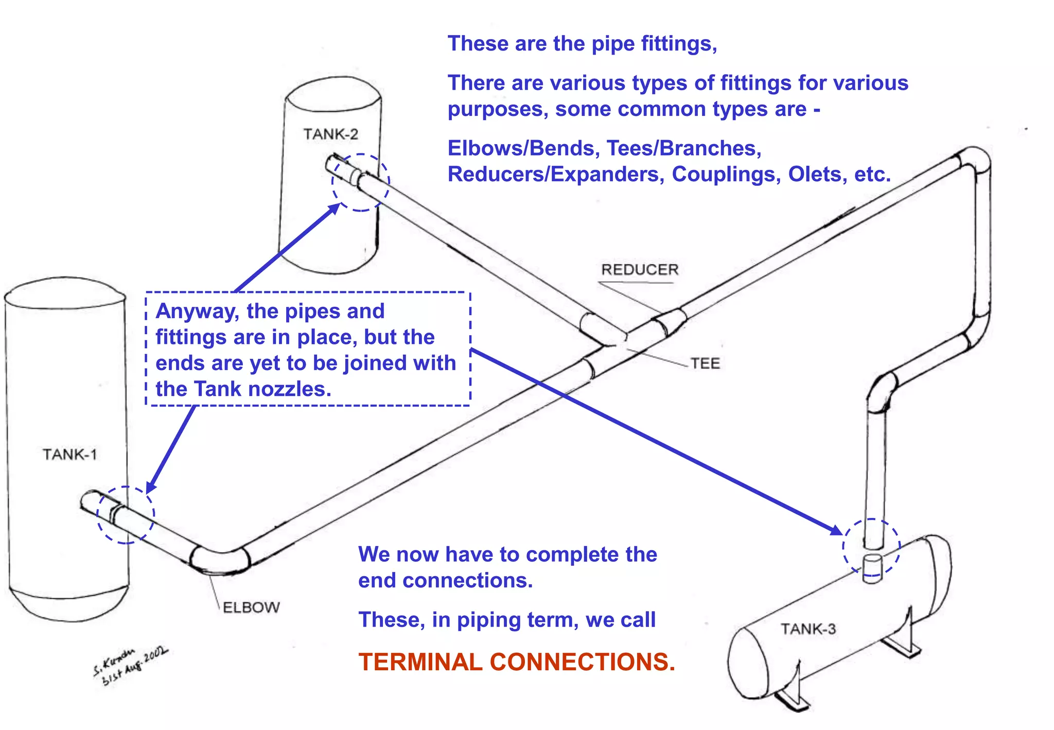
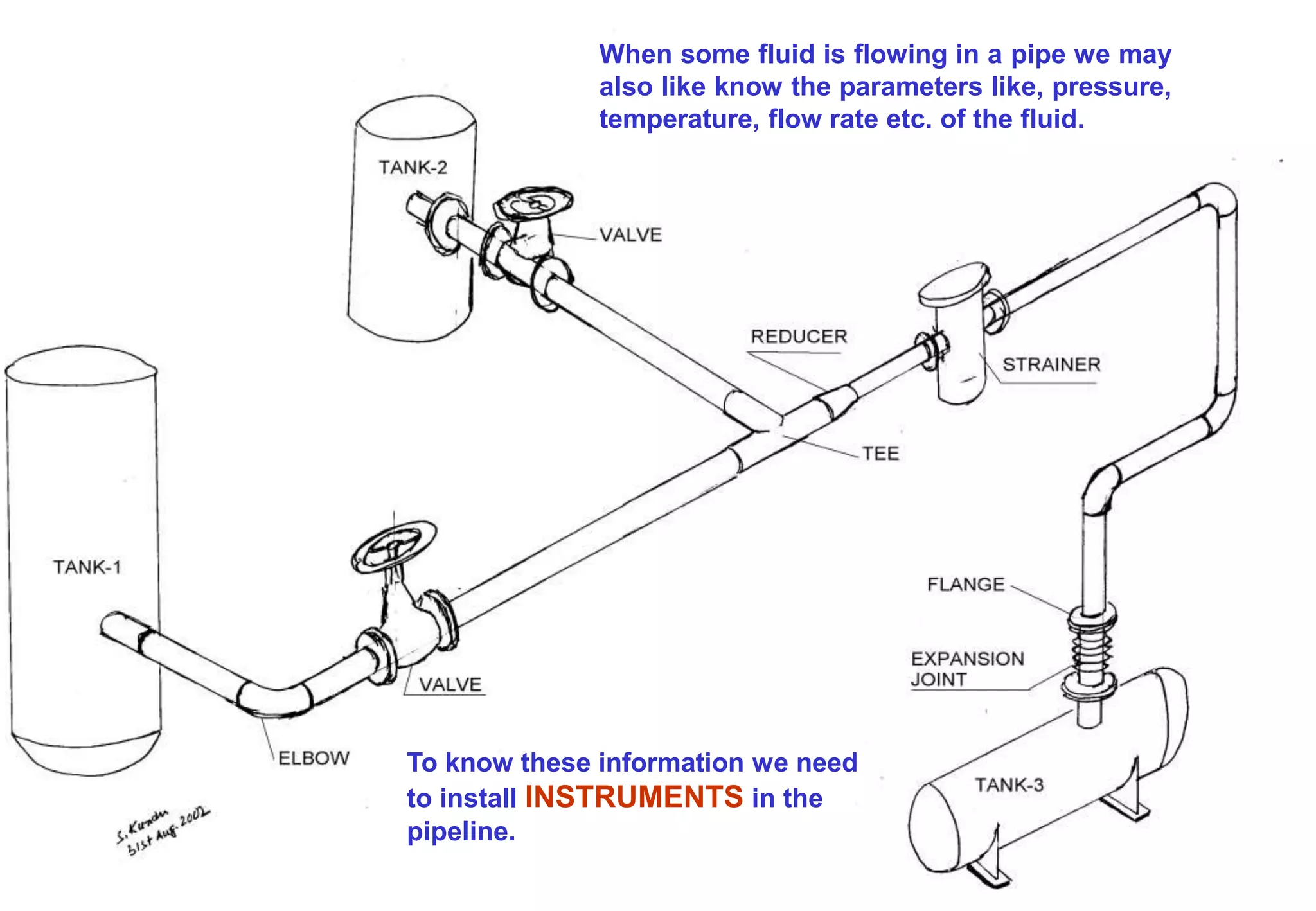
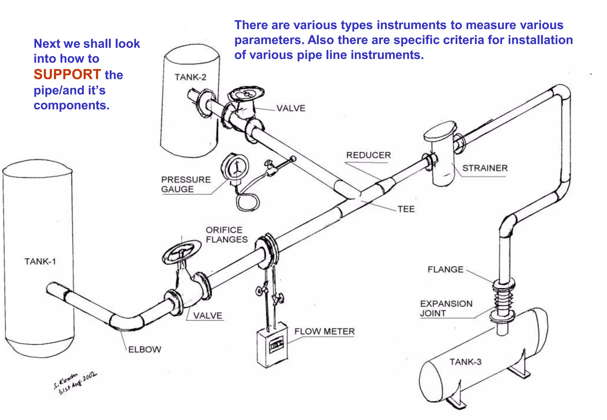
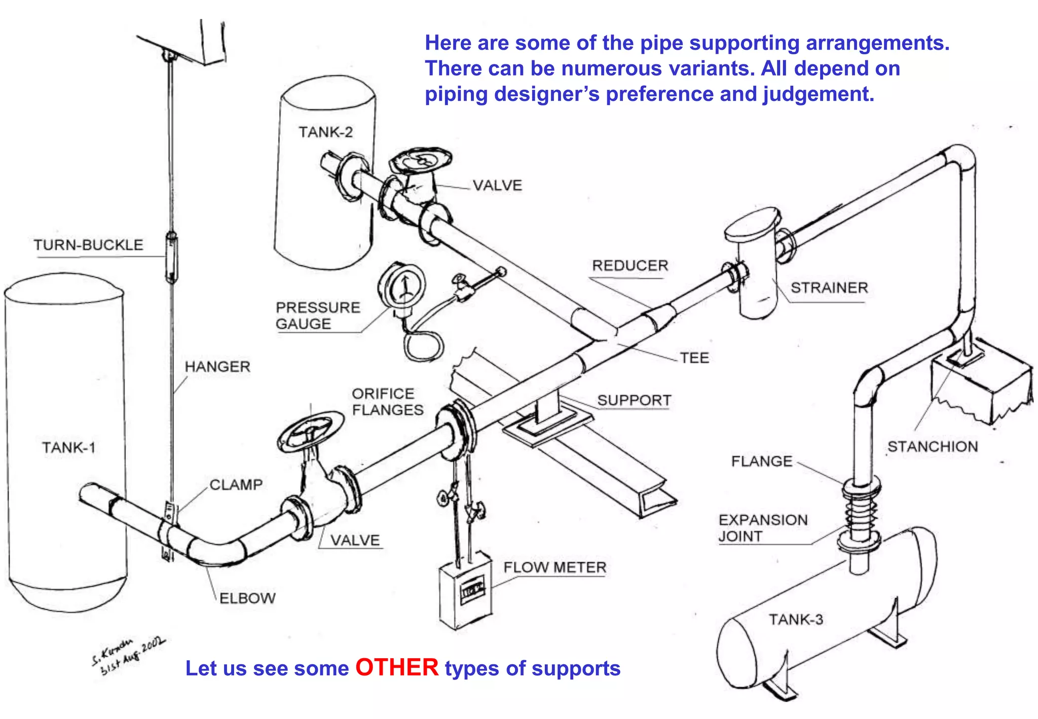
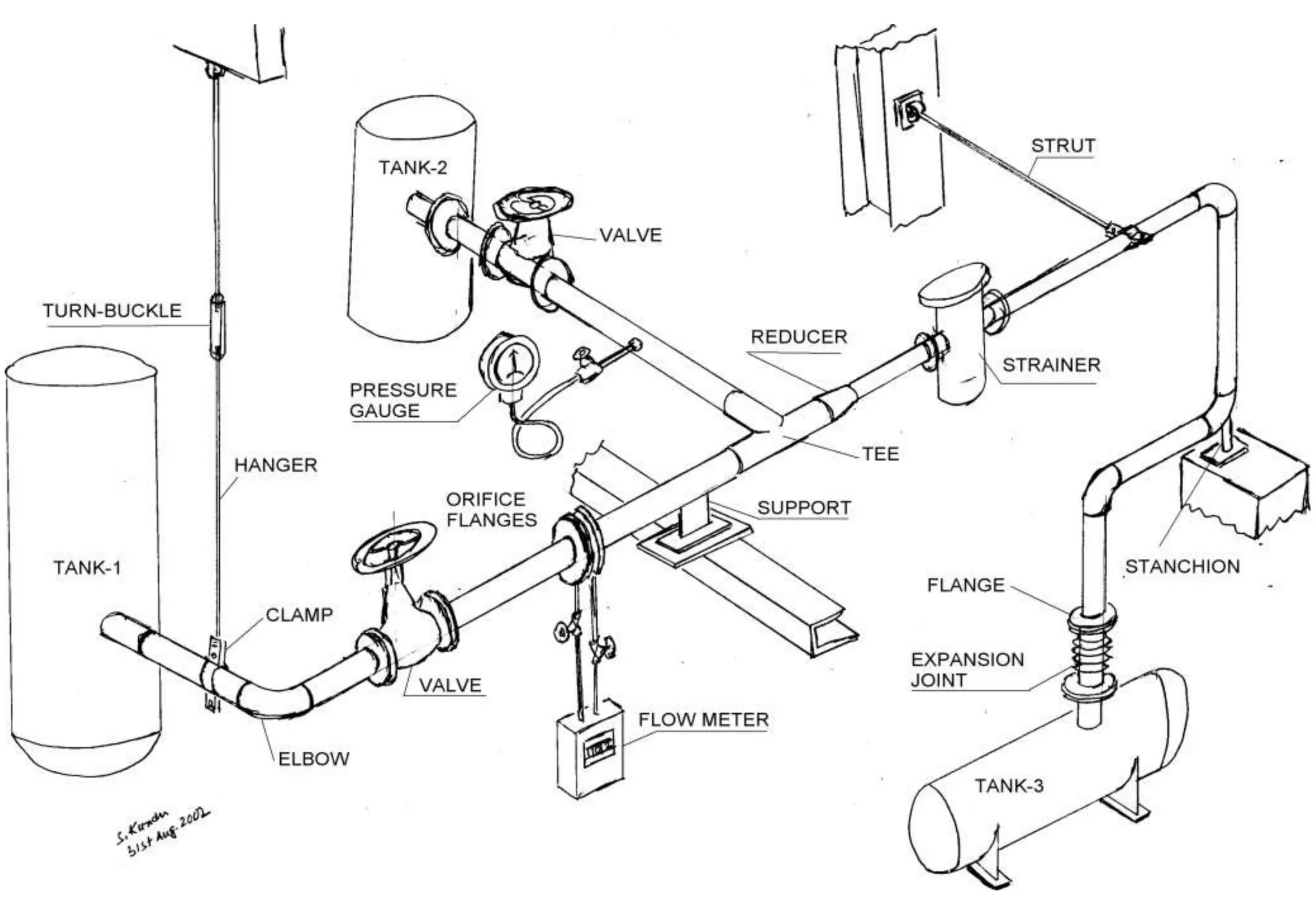
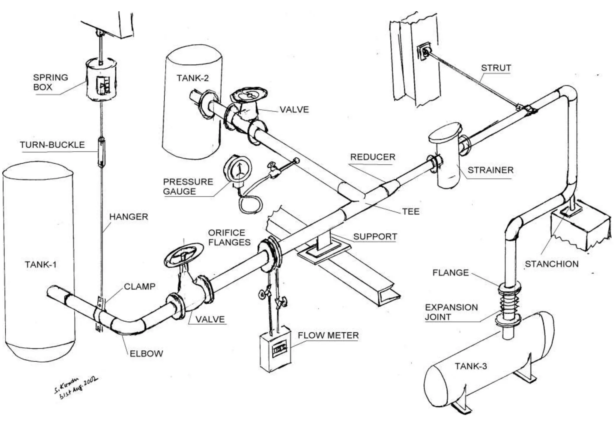
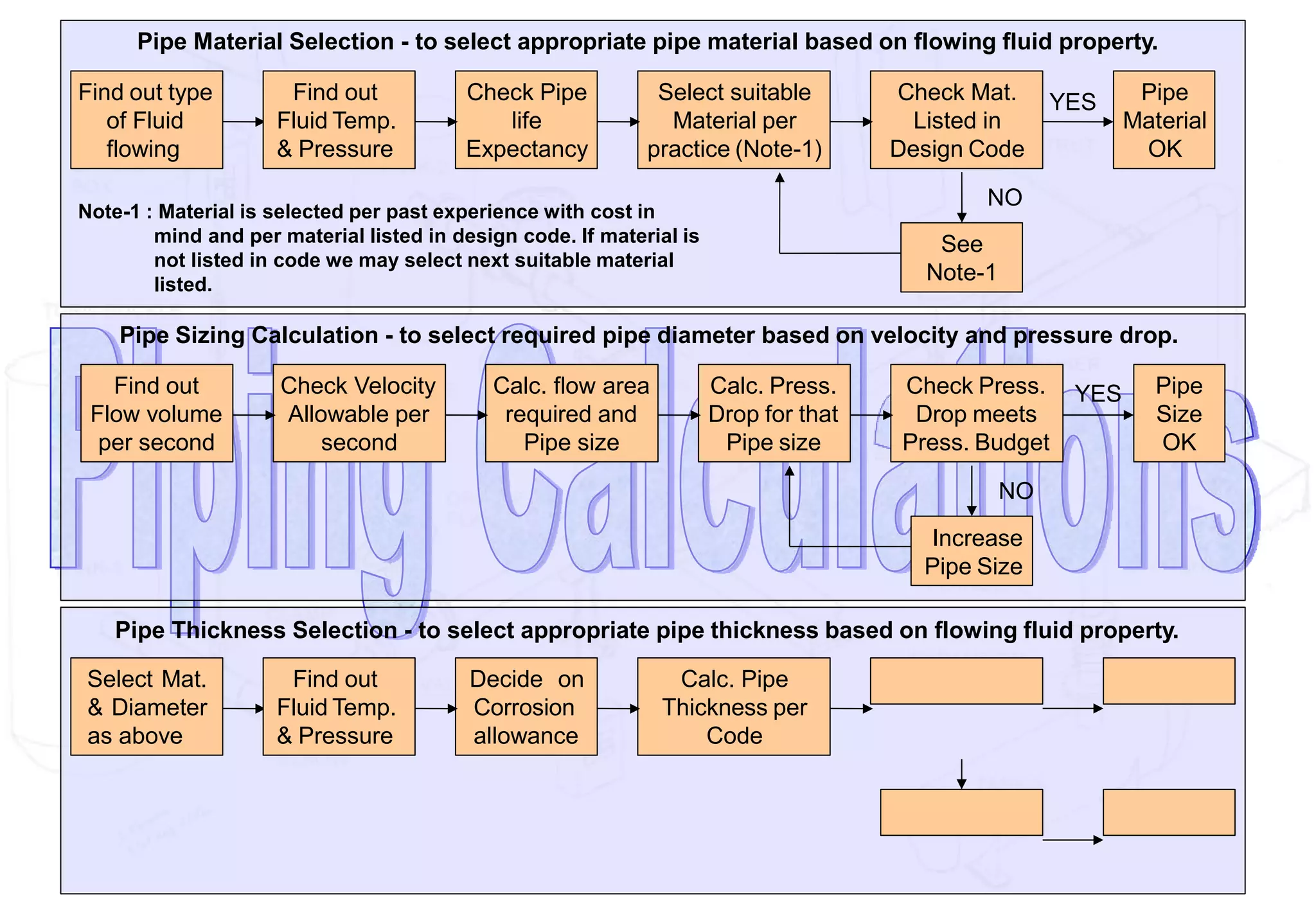
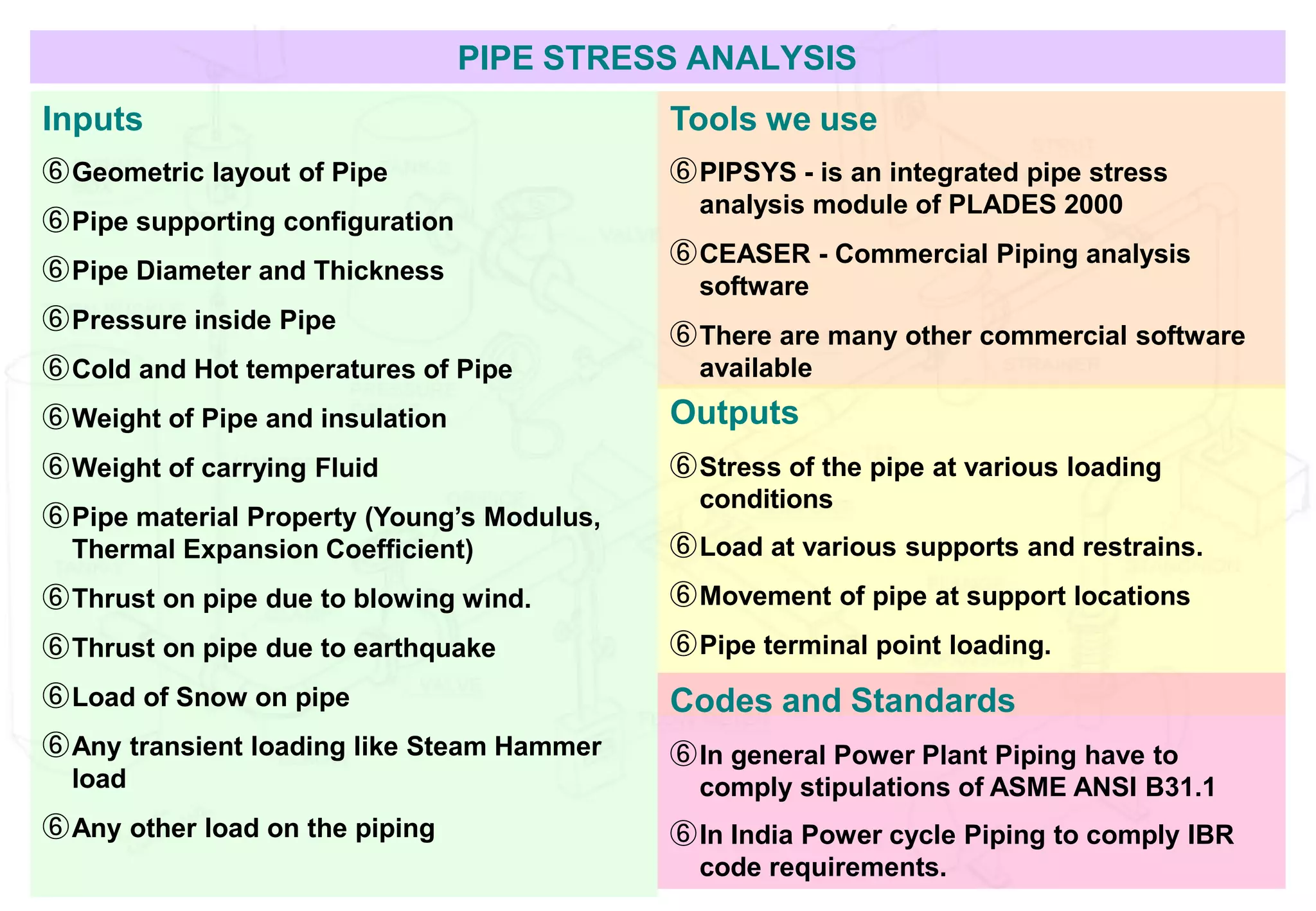
Piping is used to convey liquids, gases, or materials through a process plant. Key considerations for piping design include selecting pipe sizes and materials based on flow properties, installing necessary fittings, valves, instruments and supports, and conducting pipe stress analysis to ensure the piping can withstand pressures and temperatures. Critical high-pressure steam and water lines require special attention to flexibility and stress analysis to safely manage thermal expansion and prevent failures.
Introduction to Piping System
A pipe can be defined as a tube made of metal, plastic, wood, concrete or fiberglass. Pipes are used to carry liquids, gases, slurries, or fine particles. A piping system is generally considered to include the complete interconnection of pipes, including in-line components such as pipe fittings and flanges. Pumps, heat exchanges, valves and tanks are also considered part of piping system. Piping systems are the arteries of our industrial processes and the contribution of piping systems are essential in an industrialized society.
Fig. 1 illustrates the magnitude of piping required in a typical chemical process plant. Piping systems accounts for a significant portion of the total plant cost, at times as much as one-third of the total investment. Piping systems arranged within a very confined area can be a added challenge to piping and support engineers.
Figure 1
The initial design of a piping system is established by the functional requirements of piping a fluid from one point to another. The detailed design is decided by criteria such as type of fluid being transported, allowable pressure drop or energy loss, desired velocity, space limitations, process requirements like free drain or requirement of straight run, stress analysis, temperature of fluid, etc. The supporting of piping systems requires a significant engineering, design, fabrication and erection effort. In some cases, special structures (like structural T or inverted L, cantilevers, U portals, pedestals, etc) must be built solely for the purpose of supporting piping systems.
Piping Material
The material to be used for pipe manufacture must be chosen to suit the operating conditions of the piping system. Guidance of selecting the correct material can be obtained from standard piping codes. As an example, the ASME Code for Pressure Piping contains sections on Power Piping, Industrial Gas and Air Piping, Refinery and Oil Piping, and Refrigeration
Piping Systems. The objective being to ensure that the material used is entirely safe under the operating conditions of pressure, temperature, corrosion, and erosion expected. Some of the materials most commonly used for power plant piping are discussed in the following sections.
Steel – Steel is the most frequently used material for piping. Forged steel is extensively used for fittings while cast steel is primarily used for special applications. Pipe is manufactured in two main categories – seamless and welded.
Cast Iron – Cast iron has a high resistance to corrosion and to abrasion and is used for ash handling systems, sewage lines and underground water lines. It is, however, very brittle and is not suitable for most power plant services. It is made in different grades such as gray cast iron, malleable cast iron and ductile cast iron.
Brass and Copper – Non-ferrous material such as copper and copper alloys are used in power plants in instrumentation and water services where temperature is not a prime factor.
This Presentation is about Fundamentals of Piping it includes following points & Describes its each points as follows:-
1.Concept layout drawing
2.Piping components & their Access Requirements
3.Straight Length Requirements
4.Orientations of various taping and components
5.Piping drains and vents
6.Insulations
7.Material & Sizing
8.Critical piping system consideration
9.pinpe stress analysis
10.Pipe supports
It is a Tubular item made of metal, plastic, glass etc. meant for conveying Liquid, Gas or any thing that flows.
It is a very important component for any industrial plant. And it’s engineering plays a major part in overall engineering of a Plant.
FUNCTION OF PIPING ENGINEERING
• PIPING ENGINEERING TEAM
• PLANT LAYOUT
• LAYOUT
• PIPE FITTINGS CLASSIFICATION
• VALVE CLASSIFICATION BASED ON FUNCTION
• PIPE ROUTING
• STRESS ANALYSIS
• OBJECTIVE
• REQUIREMENTS OF SUPPORTS IN PIPING SYSTEM
• TYPE OF SUPPORTS
• FAMILIARIZATION WITH STRESS SYMBOLS
• MATERIAL ENGINEERING
• BASIS FOR MATERIALS SELECTION
• MATERIAL SELECTION DIAGRAM
• MATERIAL SELECTION AS A FUNCTION OF TEMPERATURE
Here's a presentation on piping engineering in PDF format, now available for all. This presentation covers the basics points of piping for our EPC industry. This presentation covers various aspects of piping engineering
5 Warning Signs Your BMW's Intelligent Battery Sensor Needs AttentionBertini's German Motors
IBS monitors and manages your BMW’s battery performance. If it malfunctions, you will have to deal with an array of electrical issues in your vehicle. Recognize warning signs like dimming headlights, frequent battery replacements, and electrical malfunctions to address potential IBS issues promptly.
Things to remember while upgrading the brakes of your carjennifermiller8137
Upgrading the brakes of your car? Keep these things in mind before doing so. Additionally, start using an OBD 2 GPS tracker so that you never miss a vehicle maintenance appointment. On top of this, a car GPS tracker will also let you master good driving habits that will let you increase the operational life of your car’s brakes.
In this presentation, we have discussed a very important feature of BMW X5 cars… the Comfort Access. Things that can significantly limit its functionality. And things that you can try to restore the functionality of such a convenient feature of your vehicle.
"Trans Failsafe Prog" on your BMW X5 indicates potential transmission issues requiring immediate action. This safety feature activates in response to abnormalities like low fluid levels, leaks, faulty sensors, electrical or mechanical failures, and overheating.
𝘼𝙣𝙩𝙞𝙦𝙪𝙚 𝙋𝙡𝙖𝙨𝙩𝙞𝙘 𝙏𝙧𝙖𝙙𝙚𝙧𝙨 𝙞𝙨 𝙫𝙚𝙧𝙮 𝙛𝙖𝙢𝙤𝙪𝙨 𝙛𝙤𝙧 𝙢𝙖𝙣𝙪𝙛𝙖𝙘𝙩𝙪𝙧𝙞𝙣𝙜 𝙩𝙝𝙚𝙞𝙧 𝙥𝙧𝙤𝙙𝙪𝙘𝙩𝙨. 𝙒𝙚 𝙝𝙖𝙫𝙚 𝙖𝙡𝙡 𝙩𝙝𝙚 𝙥𝙡𝙖𝙨𝙩𝙞𝙘 𝙜𝙧𝙖𝙣𝙪𝙡𝙚𝙨 𝙪𝙨𝙚𝙙 𝙞𝙣 𝙖𝙪𝙩𝙤𝙢𝙤𝙩𝙞𝙫𝙚 𝙖𝙣𝙙 𝙖𝙪𝙩𝙤 𝙥𝙖𝙧𝙩𝙨 𝙖𝙣𝙙 𝙖𝙡𝙡 𝙩𝙝𝙚 𝙛𝙖𝙢𝙤𝙪𝙨 𝙘𝙤𝙢𝙥𝙖𝙣𝙞𝙚𝙨 𝙗𝙪𝙮 𝙩𝙝𝙚 𝙜𝙧𝙖𝙣𝙪𝙡𝙚𝙨 𝙛𝙧𝙤𝙢 𝙪𝙨.
Over the 10 years, we have gained a strong foothold in the market due to our range's high quality, competitive prices, and time-lined delivery schedules.
What Exactly Is The Common Rail Direct Injection System & How Does It WorkMotor Cars International
Learn about Common Rail Direct Injection (CRDi) - the revolutionary technology that has made diesel engines more efficient. Explore its workings, advantages like enhanced fuel efficiency and increased power output, along with drawbacks such as complexity and higher initial cost. Compare CRDi with traditional diesel engines and discover why it's the preferred choice for modern engines.
Symptoms like intermittent starting and key recognition errors signal potential problems with your Mercedes’ EIS. Use diagnostic steps like error code checks and spare key tests. Professional diagnosis and solutions like EIS replacement ensure safe driving. Consult a qualified technician for accurate diagnosis and repair.
Ever been troubled by the blinking sign and didn’t know what to do?
Here’s a handy guide to dashboard symbols so that you’ll never be confused again!
Save them for later and save the trouble!
Core technology of Hyundai Motor Group's EV platform 'E-GMP'Hyundai Motor Group
What’s the force behind Hyundai Motor Group's EV performance and quality?
Maximized driving performance and quick charging time through high-density battery pack and fast charging technology and applicable to various vehicle types!
Discover more about Hyundai Motor Group’s EV platform ‘E-GMP’!
Why Is Your BMW X3 Hood Not Responding To Release CommandsDart Auto
Experiencing difficulty opening your BMW X3's hood? This guide explores potential issues like mechanical obstruction, hood release mechanism failure, electrical problems, and emergency release malfunctions. Troubleshooting tips include basic checks, clearing obstructions, applying pressure, and using the emergency release.
Comprehensive program for Agricultural Finance, the Automotive Sector, and Empowerment . We will define the full scope and provide a detailed two-week plan for identifying strategic partners in each area within Limpopo, including target areas.:
1. Agricultural : Supporting Primary and Secondary Agriculture
• Scope: Provide support solutions to enhance agricultural productivity and sustainability.
• Target Areas: Polokwane, Tzaneen, Thohoyandou, Makhado, and Giyani.
2. Automotive Sector: Partnerships with Mechanics and Panel Beater Shops
• Scope: Develop collaborations with automotive service providers to improve service quality and business operations.
• Target Areas: Polokwane, Lephalale, Mokopane, Phalaborwa, and Bela-Bela.
3. Empowerment : Focusing on Women Empowerment
• Scope: Provide business support support and training to women-owned businesses, promoting economic inclusion.
• Target Areas: Polokwane, Thohoyandou, Musina, Burgersfort, and Louis Trichardt.
We will also prioritize Industrial Economic Zone areas and their priorities.
Sign up on https://profilesmes.online/welcome/
To be eligible:
1. You must have a registered business and operate in Limpopo
2. Generate revenue
3. Sectors : Agriculture ( primary and secondary) and Automative
Women and Youth are encouraged to apply even if you don't fall in those sectors.
Fleet management these days is next to impossible without connected vehicle solutions. Why? Well, fleet trackers and accompanying connected vehicle management solutions tend to offer quite a few hard-to-ignore benefits to fleet managers and businesses alike. Let’s check them out!
Bài tập - Tiếng anh 11 Global Success UNIT 1 - Bản HS.doc
analysis.pptx
1. Piping Fundamentals – For Fresher Engineers
Piping System - What is that?
Concept Layout Development
Piping Components & their access requirement.
Straight length requirements.
Orientation of various tapings, components, etc.
Piping Drains & Vents
Insulation.
Material & Sizing
Critical piping system consideration.
Pipe Stress Analysis.
Pipe Supports
2. Piping Fundamentals – For Fresher Engineers
Let us first Discuss about WHAT IS PIPE!
It is a Tubular item made of metal, plastic, glass etc.
meant for conveying Liquid, Gas or any thing that
flows.
It is a very important component for any industrial
plant. And it’s engineering plays a major part in overall
engineering of a Plant.
In next few pages we shall try to familiarize about pipe
and it’s components.
3. In any plant various fluids flow through pipes
from one end to other.
Now let us start with a plant where we see three
tanks.
Tank-1, Tank-2 and Tank-3
We have to transfer the content of Tank no. 1 to
the other two tanks.
We will need to connect pipes to transfer the
fluids from Tank-1 to Tank-2 and Tank-3
LET US BRING THE PIPES.
4. We have just brought the pipes, now we
need to solve some more problems.
Pipes are all straight pieces.
We need some
branch
connections
We need some bend
connections
To solve these
problems we need the
pipe components,
which are called
PIPE FITTINGS
5. These are the pipe fittings,
There are various types of fittings for various
purposes, some common types are -
Elbows/Bends, Tees/Branches,
Reducers/Expanders, Couplings, Olets, etc.
Anyway, the pipes and
fittings are in place, but the
ends are yet to be joined with
the Tank nozzles.
We now have to complete the
end connections.
These, in piping term, we call
TERMINAL CONNECTIONS.
6. These are flanged joints
This is a welded joint
So far this is a nice arrangement.
But there is no control over the flow from Tank-1
to other tanks.
We need some arrangement to stop the
flow if needed
To control the flow in a pipe line we
need to fit a special component.
That is called - VALVE
7. There are many types of valves, categorized
based on their construction and functionality,
Those are - Gate, Globe, Check, Butterfly, etc.
Other than valves another important
line component of pipe line is a filter,
which cleans out derbies from the
flowing fluid. This is called a
STRAINER
8. Here we see a more or less functional piping
system, with valves and strainer installed.
Let us now investigate some aspects of pipe
flexibility.
If this tank nozzle
expands, when
the tank is hot.
In such case we need to fit a flexible
pipe component at that location,
which is called an EXPANSION
JOINT
9. When some fluid is flowing in a pipe we may
also like know the parameters like, pressure,
temperature, flow rate etc. of the fluid.
To know these information we need
to install INSTRUMENTS in the
pipeline.
10. There are various types instruments to measure various
parameters. Also there are specific criteria for installation
of various pipe line instruments.
Next we shall look
into how to
SUPPORT the
pipe/and it’s
components.
11. Here are some of the pipe supporting arrangements.
There can be numerous variants. All depend on
piping designer’s preference and judgement.
Let us see some OTHER types of supports
12.
13.
14. We have just completed a pipe line design.
We shall rewind and check how it is really done in practice.
➠ First the flow scheme is planned,
1) What, 2) From what point, 3) To which point
➠ Pipe sizes are selected, pipe material and pipe wall thickness are selected.
➠ Types of Valves are planned
➠ Also the types of instruments required are planned
We represent the whole thing in a drawing which is called Piping and
Instrumentation Drawing, in short P&ID. For P&ID generation we use SPP&ID
software.
By this time you have already come to know that while we prepare P&IDs in
SPP&ID, we enter all the pipe lines system information in the drawing.
So the SPP&ID drawing is an Intelligent drawing which under it’s surface carries all
the information about a pipe like, Pipe size, Flowing Fluid, etc.
Let us see a P&ID prepared in SPP&ID
15.
16. This is screen picture of P&ID made by SPP&ID
If we click on any line it will show the Data embedded.
17. Preferable
Not Preferable
After the P&ID is ready we start the layout work.
Here we carryout pipe routing / layout in Virtual 3D environment.
We use PDS 3D software to route piping in the Plant virtual 3D space.
We call this as piping modeling or physical design.
While development of piping layout we have to consider the following
➠ Piping from source to destination should be as short as possible with minimum
change in direction.
➠ Should not hinder any normal passage way. Also should not encroach any
equipment maintenance space.
18. While carrying out pipe routing we also need to consider the following
➠ Valves, strainers, instruments on the pipe should be easily accessible.
➠ If needed separate ACCESS PLATFORMS to be provided to facilitate these.
➠ Desired location and orientation of valves / instruments and other pipe
components are to be checked and maintained, like some valves or strainers
can only be installed in horizontal position.
➠ Specific requirements for instrument installation to be checked, like
temperature gauge can not be installed in pipe which is less than 4 inch in size.
➠ Specific requirements of STRAIGHT LENGTH of pipe for some components to
be maintained, like for flow orifice we need to provide 15 times diameter
straight pipe length at upstream of orifice and 5 times diameter straight at down
stream of orifice.
Example of Straight length requirement for Flow Orifice
19. ⑥ For Pipeline which shall carry liquid, we have to make sure that all air is
allowed to vent out of the line when the line is filled with liquid.
⑥ To achieve this a VENT connection with Valve is provided at the top most point
of the pipeline.
⑥ Also arrangement is kept in the
pipeline so that liquid can be
drained out if required.
⑥ To achieve this a DRAIN
connection with Valve is provided
at the lowest point of the pipeline
⑥ Pipes are also slopped towards low
points.
Let us look
into typical
Vent and
Drain
arrangement
in a pipeline
20. Let us have a look into a piping model done by PDS 3D
This is a 3D model
of Feed water line
along with pumps
and other
accessories
21. INSULATION - When hot fluid flows through pipe then generally pipe is
insulated.
There are two primary reasons for insulating the pipe carrying hot fluid.
Containing the heat inside the pipe. Insulation preserves the heat of the fluid. It
is called Hot Insulation
Personnel safety, so that people do not get burn injury by touching hot surface
Cooldfpipe.sItarisec
a
a
l
s
l
l
o
e
d
i
n
P
s
e
u
r
l
a
s
t
o
e
n
d
n
e
lProtection Insulation
Cold or chilled fluid carrying pipes are insulated to prevent heating of cold fluid
from outside. It is called Cold Insulation.
Some times cold pipes are insulated to prevent condensation of atmospheric
water vapor on pipe surface. It is called Anti-Sweat Insulation.
Other types of Insulation
When gas flows through pipes at high velocity, it creates noise. In such cases
pipes are insulated to reduce noise. It is called Acoustic Insulation.
Some times pipe and it’s content are heated from outside, by heat tracing
element. In that case pipe along with heat tracing element are insulated to
conserve the heat of the tracer. It is called Heat Tracing Insulation.
22. INSULATION MATERIAL - The insulating material should be bad conductor of heat.
There are two basic categories
1) Fibrous Material, which has large voids full of air between fibers - Cork, Glass Wool,
Mineral Wool, Organic Fibers. Note stagnant air is a bad conductor.
2) Cellular Material, which has closed void cells full or air - Calcium Silicate, Cellular
Glass (Foam Glass), Polyurethane Foam (PUF), Polystyrene (Thermocol), etc.
Some times Cast material like Cement Plaster or Plaster of Paris are also used.
INSULATION CLADDING - Insulation materials are generally soft or fragile. So the
outer surface of insulation are protected with Aluminum sheet or GI sheet
cladding.
Have a look at how
pipes are insulated,
and general
components of
insulation
23. Pipe Sizing Calculation - to select required pipe diameter based on velocity and pressure drop.
Find out Check Velocity Calc. flow area Calc. Press.
Flow volume Allowable per required and Drop for that
per second second Pipe size Pipe size
Check Press.
Drop meets
Press. Budget
Pipe
Size
OK
YES
Pipe Material Selection - to select appropriate pipe material based on flowing fluid property.
Find out type
of Fluid
flowing
Check Pipe
life
Expectancy
Select suitable
Material per
practice (Note-1)
Check Mat.
Listed in
Design Code
Pipe
Material
OK
YES
See
Note-1
NO
Note-1 : Material is selected per past experience with cost in
mind and per material listed in design code. If material is
not listed in code we may select next suitable material
listed.
Find out
Fluid Temp.
& Pressure
NO
Increase
Pipe Size
Pipe Thickness Selection - to select appropriate pipe thickness based on flowing fluid property.
Select Mat.
& Diameter
as above
Decide on
Corrosion
allowance
Calc. Pipe
Thickness per
Code
Find out
Fluid Temp.
& Pressure
24. ⑥ In Power plant there are some piping which carries steam at high pressure and
temperature. And also there are piping which carries water at High pressure.
These pipes carries the main cycle steam and water of the steam power plant.
⑥ These pipelines are call the CRITICAL PIPING.
⑥ Very special care are taken for design of these piping.
⑥ First the pipe material selection for such piping is very important as it has to
withstand the high pressure and may be also high temperature.
⑥ As these pipes carry the main system fluid of the power plant, they are given
the right of way, and routed at beginning of the overall plant layout.
⑥ Steam pipes run at very high temperature and the hot pipes expand. We have to
built in flexibility in the high temperature pipe routing so that the expansion
force is absorbed within the piping.
⑥ Also there should be enough flexibility in these pipe routing so that high loads
are not transferred to the nozzles of Turbine or Pumps
⑥ There are many recognized international codes which lay down guide lines and
mandatory requirements for design of such piping.
⑥ The most important codes used by power plant piping engineers are
⑥ ASME ANSI B31.1- Power Piping Code & IBR - the Indian Boiler Regulation
25. Pipe Stress Analysis
⑥ We have already seen that some of the pipes are subjected to high pressure
and high temperature. Also pipes carry the load of the flowing fluid.
⑥ We need to check and confirm the pipe is not going to fail with these loading.
⑥ This process of checking the stress developed in the piping due to various
loading is called Pipe Stress Analysis/Flexibility analysis.
⑥ In the process of Analysis we apply various postulated loading on the pipe and
find out the stress resulted from these loading.
e
ch
⑥ Then w eck wit h
go
ng
verni odes if those stresses generated are
ac eptable or not.
⑥ We check support load & movement for various loading condition.
⑥ We also check out the terminal point loading generated fro m
pi
pe to the
equipment connected to the pipe. This loading are to be within acceptable
limits of the equipment suggested by the vendors.
⑥ We also find out the pipe growth due to change in temperature and need to
keep the movement of pipe within acceptable limits.
⑥ Pipe Stress Analysis is an Interactive and Iterative process. Each step is
checked
⑥ If a check fails we have to go back, modify the layout and restart the analysis.
26. PIPE STRESS ANALYSIS
Inputs
⑥Geometric layout of Pipe
⑥Pipe supporting configuration
⑥Pipe Diameter and Thickness
⑥Pressure inside Pipe
⑥Cold and Hot temperatures of Pipe
⑥Weight of Pipe and insulation
⑥Weight of carrying Fluid
⑥Pipe material Property (Young’s Modulus,
Thermal Expansion Coefficient)
⑥Thrust on pipe due to blowing wind.
⑥Thrust on pipe due to earthquake
⑥Load of Snow on pipe
⑥Any transient loading like Steam Hammer
load
⑥Any other load on the piping
Tools we use
⑥PIPSYS - is an integrated pipe stress
analysis module of PLADES 2000
⑥CEASER - Commercial Piping analysis
software
⑥There are many other commercial software
available
Outputs
⑥Stress of the pipe at various loading
conditions
⑥Load at various supports and restrains.
⑥Movement of pipe at support locations
⑥Pipe terminal point loading.
Codes and Standards
⑥In general Power Plant Piping have to
comply stipulations of ASME ANSI B31.1
⑥In India Power cycle Piping to comply IBR
code requirements.
27. Types of Pipe Supports
In the beginning of this discussion we
talked about various types of pipe
supports. Here is some elaboration
⑥There are three general types
⑥Rigid type (no flexibility in the
direction of restrain)
⑥Spring type (Allows pipe
movement in direction of loading)
⑥Dynamic Support (Degree of
restrain depends on acceleration
of load)
⑥There are two types of spring
support
⑥Variable load type, here support
load changes as the pipe moves.
⑥Constant load support, the load
remains constant within some
range of movement.
Constant Load Spring
Variable Spring
Rigid
Hanger
Rigid
Support
Dynamic Support,
Snubber
Rigid Support
28. Some Special Considerations for Piping
When pipes are routed UNDER GROUND (Buried) following points to be kept in mind:
⑥Minimum pipe size to be routed under ground shall be not less than1 inch.
⑥Avoid flange joint in U/G piping.
⑥Keep in mind if pipe leaks U/G, it will be difficult to detect, so avoid U/G routing of pipe
carrying hazardous fluid.
⑥Pipe to be laid below Frost Zone at areas where ambient temperature goes below freezing.
⑥U/G, Buried piping should be properly protected from corrosion.
⑥Pipe may be properly wrapped and coated to prevent corrosion.
⑥Or U/G piping be protected by using Cathodic protection.
Freeze Protection of outdoor Piping:
⑥In the areas where the ambient temperature goes below freezing there is a possibility that
the liquid content of pipe may freeze while the plant is under shut down.
⑥ For similar case pipes are wrapped with heat tracing elements to maintain the content
temperature above freezing (around 4 deg. C) even when the ambient temp. is below
freezing.
⑥Electric Heat tracing is done by wrapping electric coil around pipe, which turns on as the
ambient temperature goes down. Pipes are insulated over the heat tracing coils.
⑥Heat tracing can also be done by winding Steam tubes around main pipes.
29. We have come to the End of Session.
Hope you have gathered the fundamentals
on the subject of Piping