Downloaded 31 times


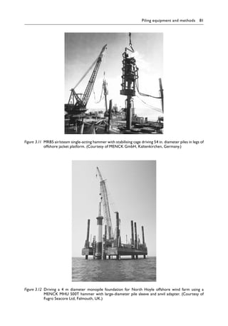
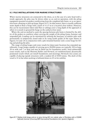
![Piling equipment and methods 121
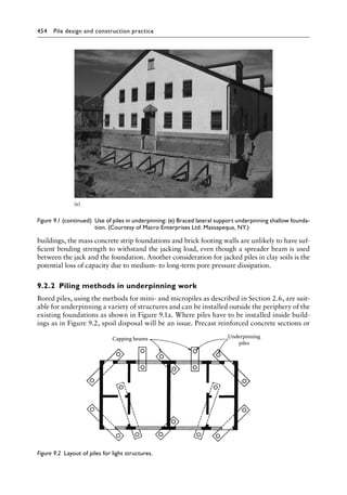
‘descent into machine-bored shafts for piling’ (see Figure 11.6). High-resolution colour CCTV
inspection is appropriate provided good lighting is available, and the absence of remould-
ing on the shelf of the under-ream should be checked by a sampling device or penetrometer.
Concreting should commence within 2 h of the inspection of the under-ream.
The final cleaning-up operation before placing concrete in a bored pile consists of remov-
ing large crumbs of soil or trampled puddled clay from the pile base. Any lumps of clay
adhering to the walls of the borehole or to the lining tubes should be cleaned off. The
reinforcing cage can then be placed and concreting commenced. The time interval between
the final cleaning-up and placing concrete should not exceed 6 h. If there is any appreciable
delay, the depth of the pile bottom should be checked against the measured drilled depth
before placing the concrete to ensure that no soil has fallen into the hole. If the reinforcing
cage is to extend only part way down the hole, it should be suspended from the top of the
pile shaft before commencing to place the concrete.
The concrete used in the pile base and shaft should be easily workable with a slump of
180 mm as recommended in BS EN 1536. As the concrete is placed in ‘free fall’ from a
chute or hopper over the bore and vibration in the bore is not feasible, the mix must be self-�
compacting, designated S4 in BS 8500-1, preferably using rounded aggregate. In addition, the
mix proportions should comply with the requirements for strength and minimum cement con-
tent in BS EN 1536, and care is needed when considering mix design for durability (see Section
10.3.1). A dry mix should be used for the first few charges of concrete if the pile base is wet.
After completing concreting, the lining tubes are withdrawn. If a loose liner is used inside an
upper casing, the former is lifted out as soon as the concrete extends above the base of the
outer tube. A vibrator of the type described in Section 3.1.5 is a useful expedient for extract-
ing the upper casings used to support soft clays or loose sand. The quantity of concrete placed
in the shaft should allow for the outward slumping which takes place to fill the space occupied
by the tube and any overbreak of the soil outside it. Concreting should be continuous so that
laitance does not form at the top of a batch, causing weakness within the shaft. Laitance on
top of the shaft on completion is inevitable. This laitance may be contaminated with water
and silt expelled from around the casing as the concrete slumps outwards to fill the gap. Thus,
the level of the concrete should be set high so that this weak laitance layer can be broken
away before bonding the pile head onto its cap. The terms of the contract should make it clear
whether or not this removal should be performed by the piling contractor.
The concrete in a pile shaft may be required to be terminated at some depth below ground
level, for example, when constructing from ground surface level, piles designed to support
a basement floor. It is a matter of some experience to judge the level at which the concrete
should be terminated, and it is difficult to distinguish between fluid concrete and thick lai-
tance when plumbing the level with a float. Where the piles are to support plunge columns,
the casting level will be considerably lower than the piling platform; the concrete mix must
be designed for an extended period of workability and maximum cohesion to reduce the
need for removing a thick layer of laitance at basement level.
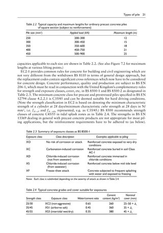
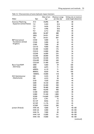
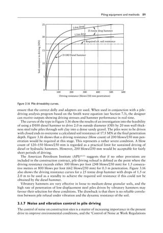
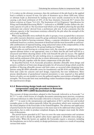
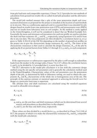
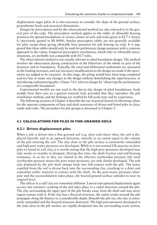
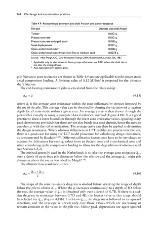
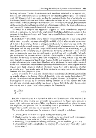
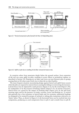
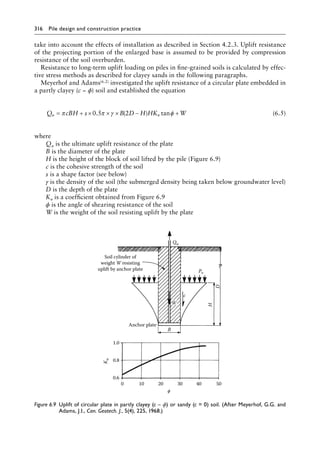
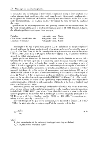
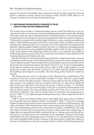
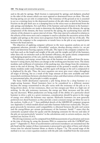
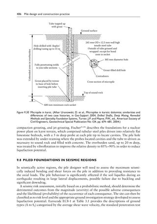
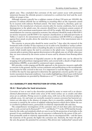
There is little guidance in either current standard specifications or BS EN 1536 on cast-
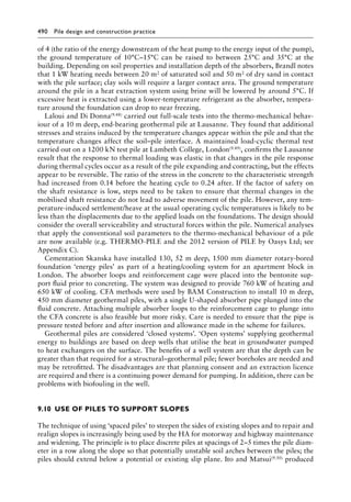
ing tolerances, but in general, it is better to leave finished pile heads high. The following
suggestions by Fleming and Lane(3.24), while somewhat conservative for all conditions, are
indicative:
Concrete cast under water +1.5 to +3 m
Concrete cast in dry uncased holes +75 to +300 mm
Concrete cast in cased holes, the greater of
a. +75 to +300 mm + (cased length)/15
b. +75 to + 300 mm + [(depth to casting level − 900 mm)/10]](https://image.slidesharecdn.com/piledesignandconstructionpracticesixtheditionpdfdrive-240129074148-da7d723b/85/Pile-Design-and-Construction-Practice-Sixth-Edition-PDFDrive-pdf-143-320.jpg)

![152 Pile design and construction practice
hole and form a slurry with the clay as the drilling tools are lowered down or raised from
the hole. Water can also soften the clay if it trickles down from imperfectly sealed-off water-
bearing strata above the clay or if hose pipes are carelessly used at ground level to remove
clay adhering to the drilling tools.
The effect of drilling is always to cause softening of the clay. If bentonite drilling slurry is
used to support the sides of the borehole, softening of the clay due to relief of lateral pres-
sure on the walls of the hole will still take place, but flow of water from any fissures will not
occur. There is a risk of entrapment of pockets of bentonite in places where overbreak has
been caused by the rotary drilling operation. This would be particularly liable to occur in
a stiff fissured clay.
After placing concrete in the pile borehole, water migrates from the unset concrete into
the clay, causing further softening of the soil. The rise in moisture content due to the com-
bined effects of drilling and placing concrete was observed by Meyerhof and Murdock(4.10),
who measured an increase of 4% in the water content of London Clay close to the interface
with the concrete. The increase extended for a distance of 76 mm from the interface.
This softening affects only the shaft. The soil within the zone of rupture beneath and sur-
rounding the pile base (Figure 4.3) remains unaffected for all practical purposes, and the end-
bearing resistance Rbk can be calculated from Equation 4.7, the value of the bearing capacity
factor Nc again being 9. However, Whitaker and Cooke(4.11) showed that the fissured structure of
London Clay had some significance on the end-bearing resistance of large bored piles, and they
suggested that if a bearing capacity factor of 9 is adopted, the characteristic shearing strength
should be taken along the lower range of the graph of shearing strength against depth. In other
clays, if cub is less than 96 kN/m2, then a pro rata reduction in Nc to 8 at a cub of 48 kN/m2 could
be considered. If bentonite drilling mud is used, slurry can be trapped beneath the pile base, and
a reduction in end-bearing resistance will be needed as described by Reese et al.(3.12)
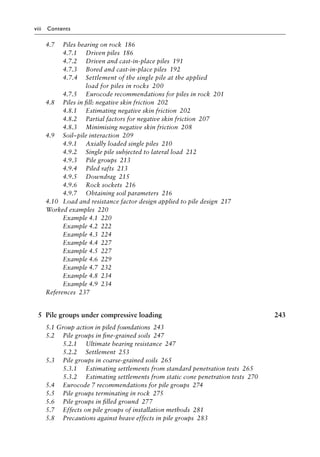
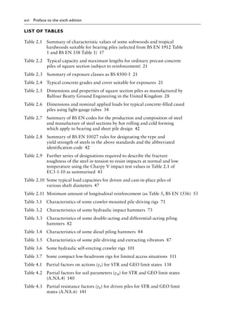
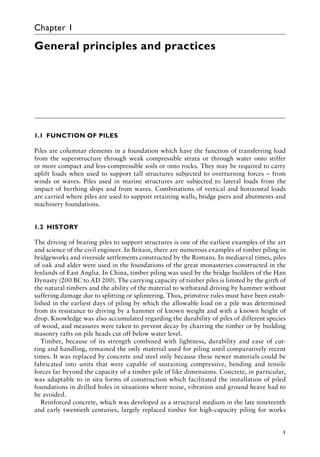
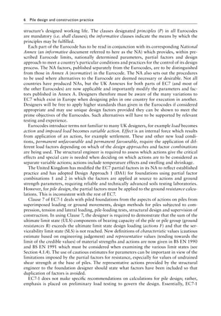
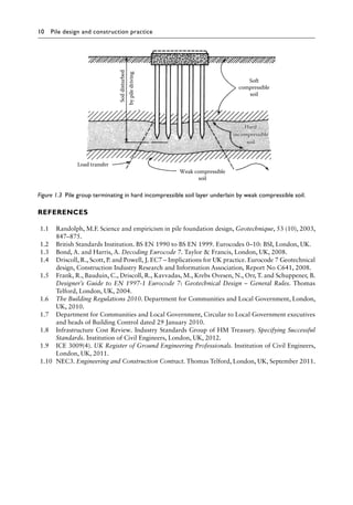
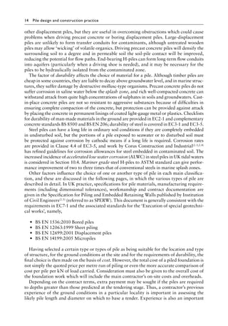
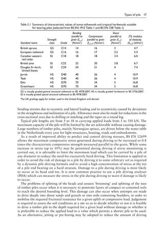
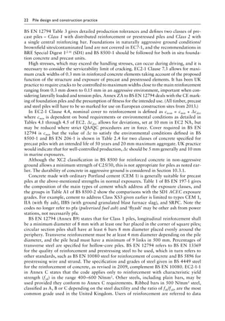
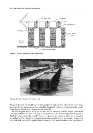
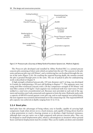
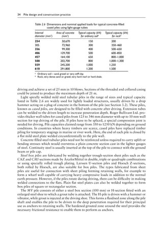
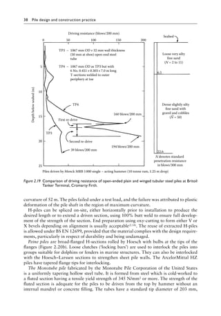
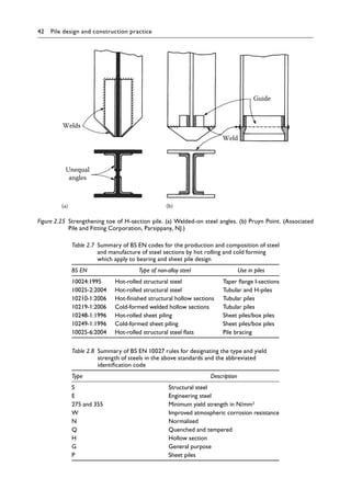
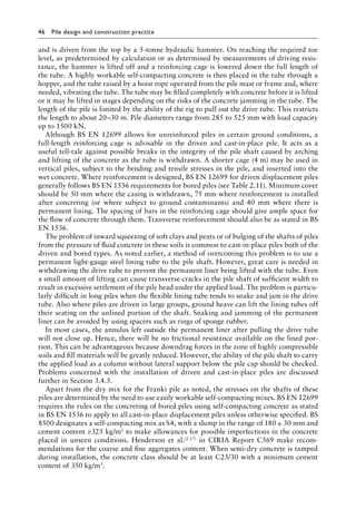
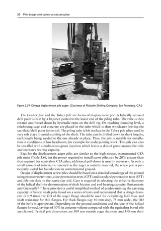
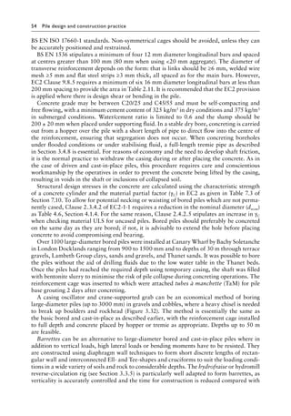
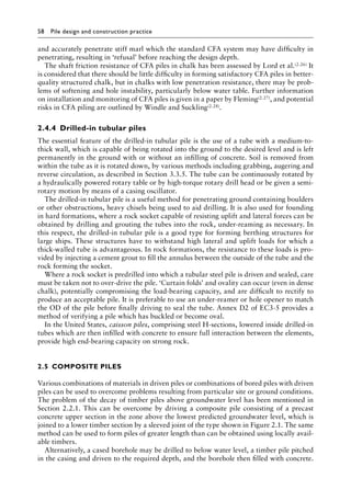
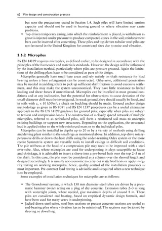
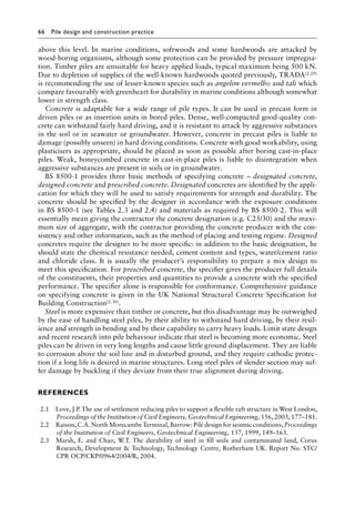
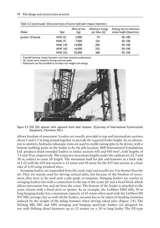
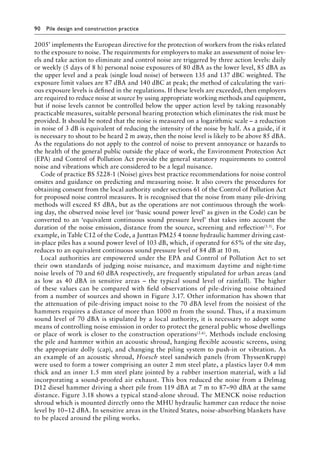
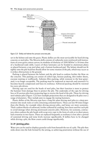
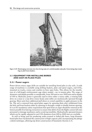
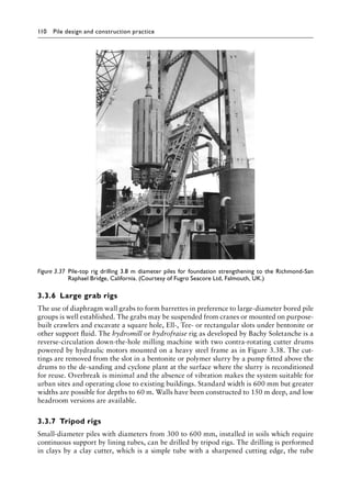
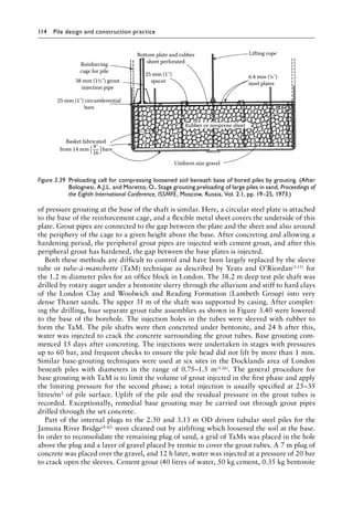
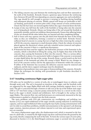
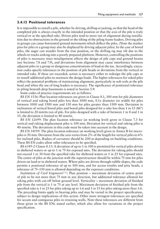
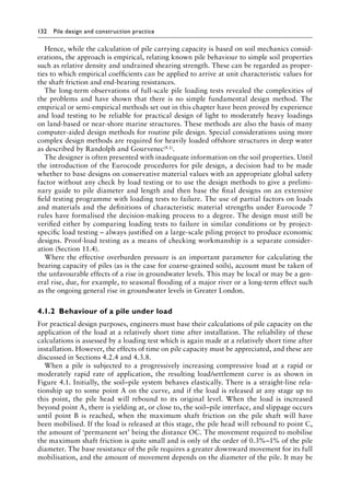
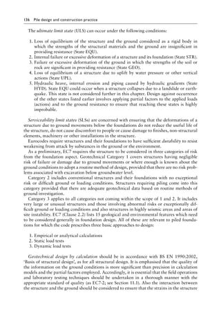
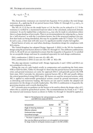
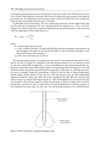
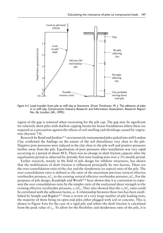
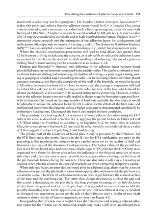
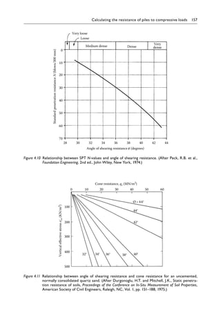
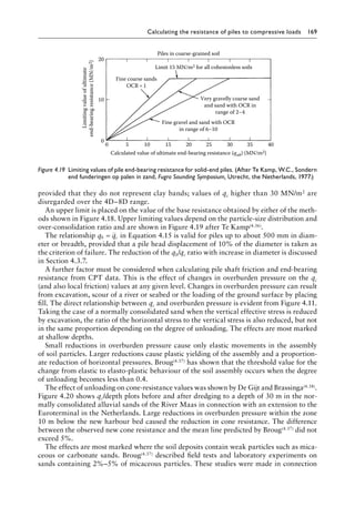
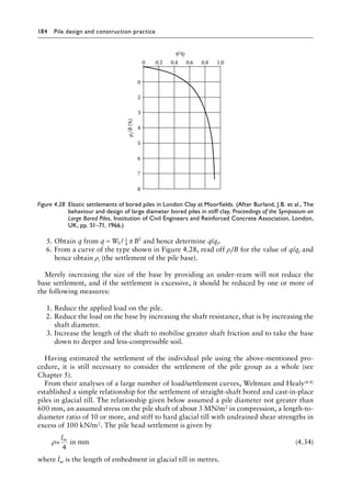
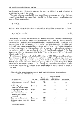
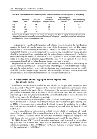
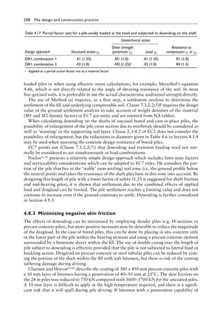
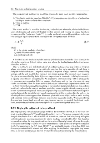
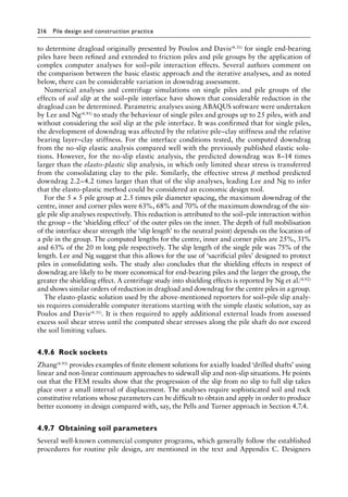
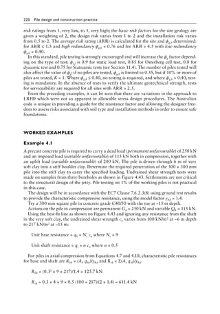
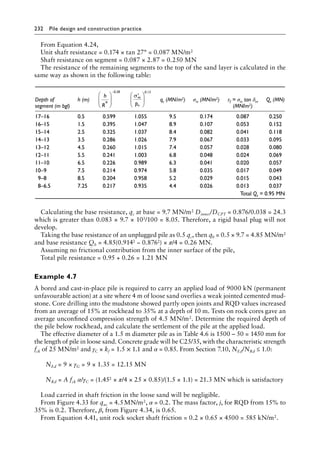
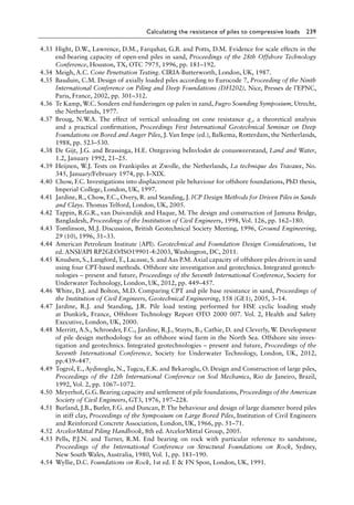
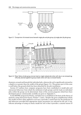
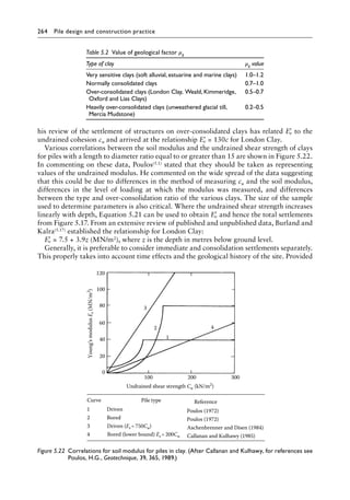
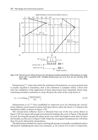
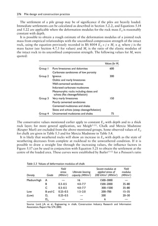
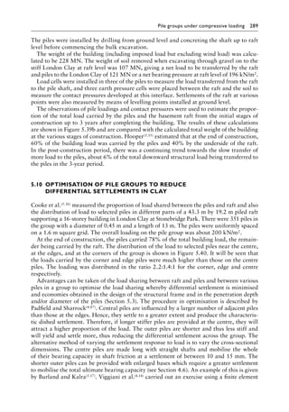
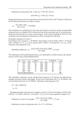
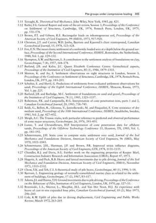
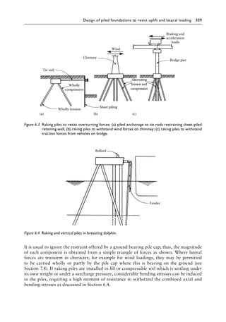
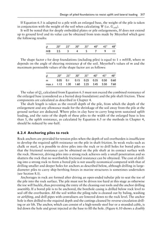
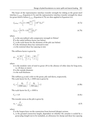
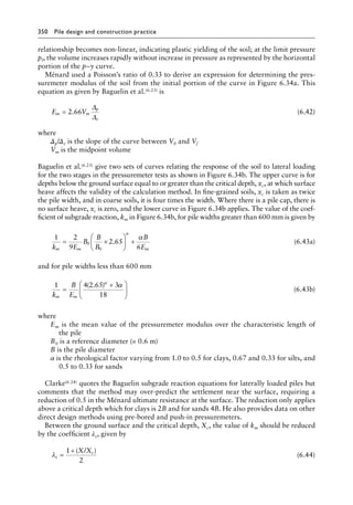
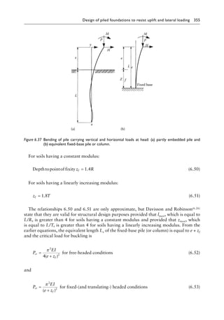
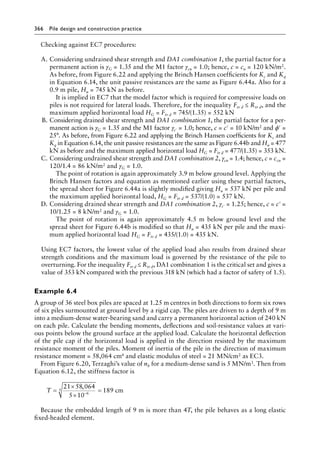
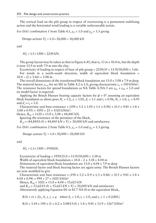
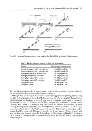
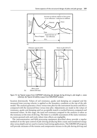
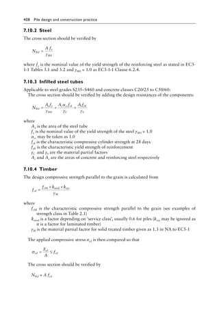
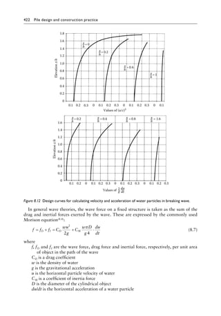
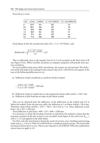
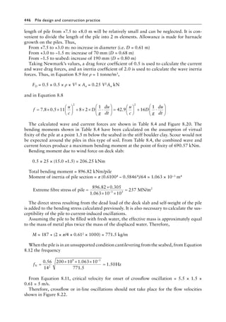
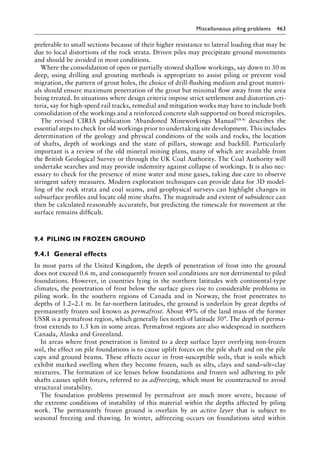
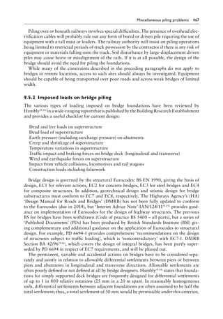
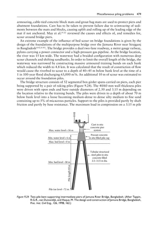
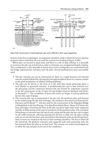
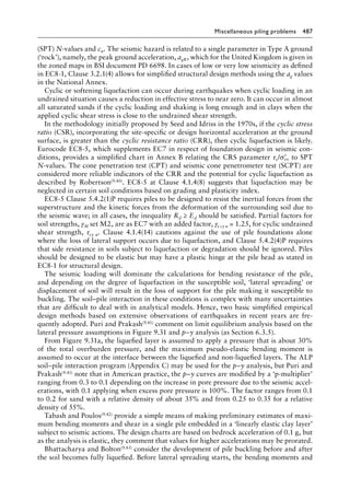
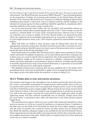
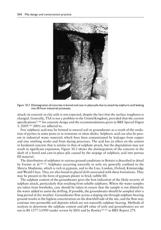
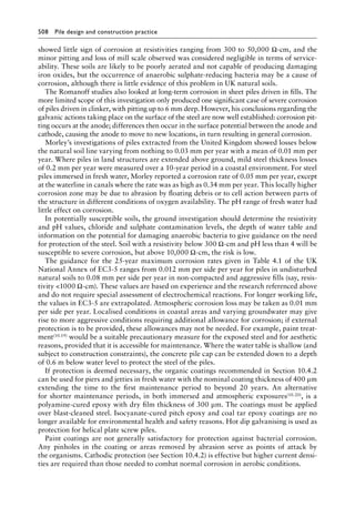
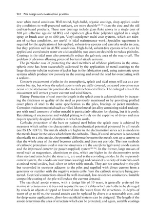
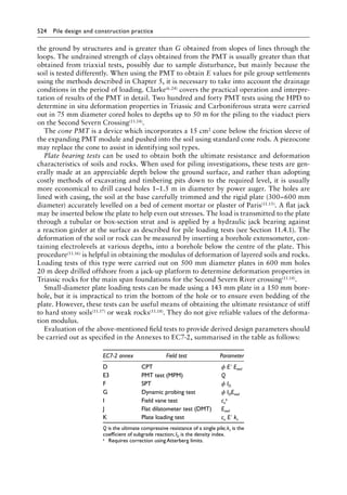
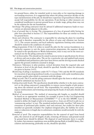
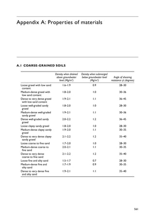
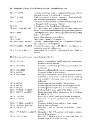
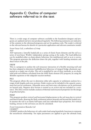
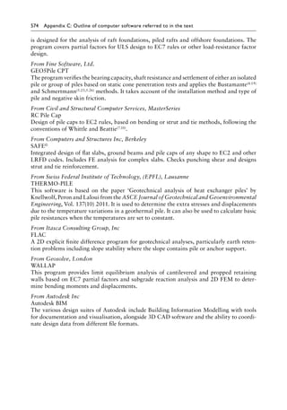
The effect of the softening on the shaft friction of bored piles in London Clay was studied
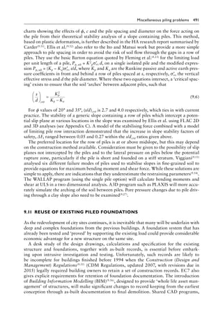
by Skempton(4.12), who showed that the adhesion factor, α, ranged from 0.3 to 0.6 for a num-
ber of loading test results. He recommended an average value of 0.45 for normal conditions
where drilling and placing concrete followed a reasonably rapid sequence with a lower value
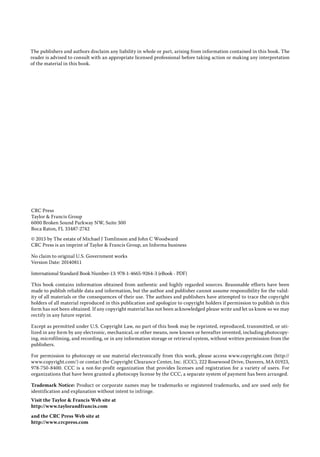
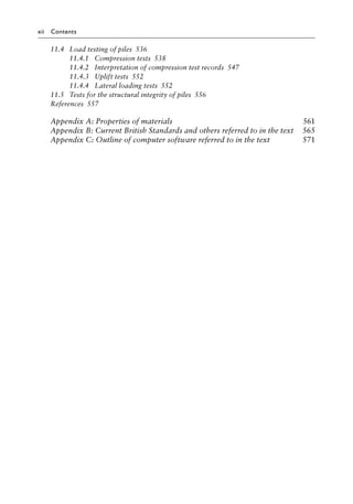
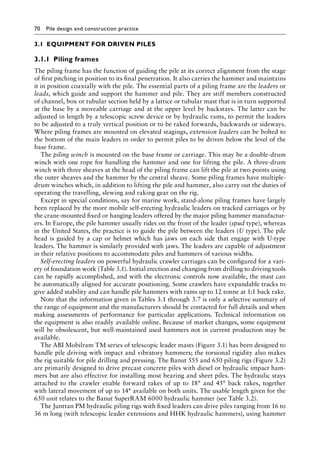
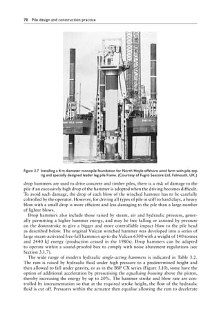
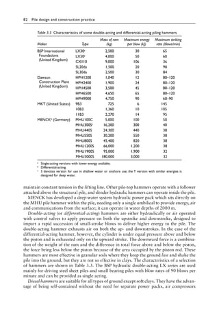
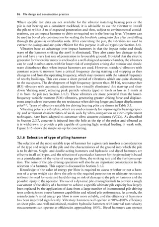
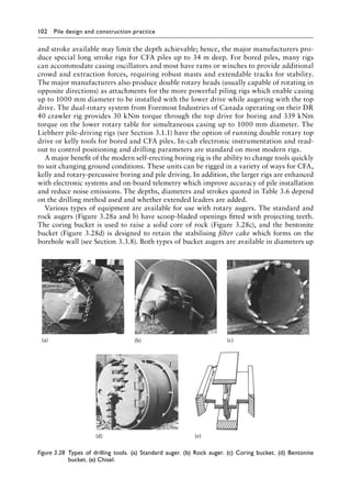
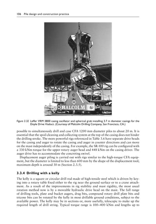
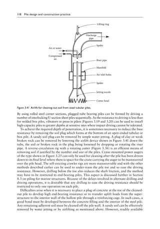
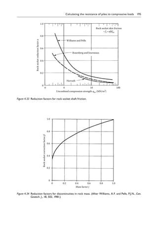
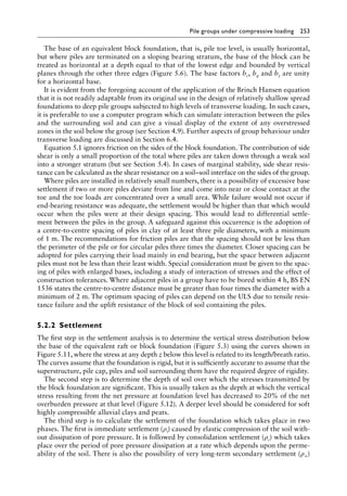
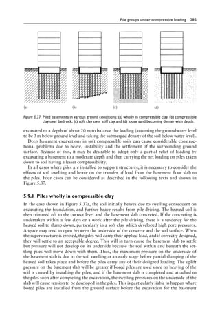
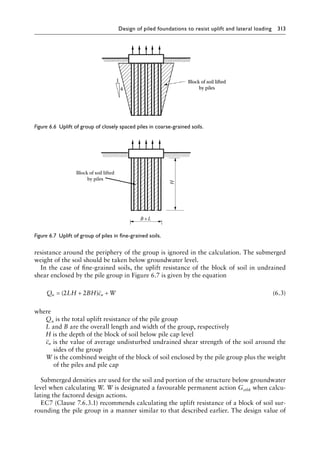
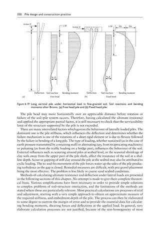
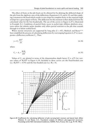
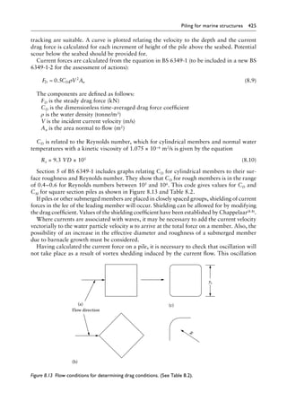
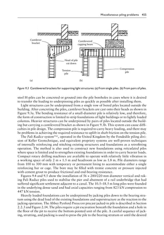
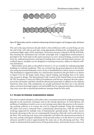
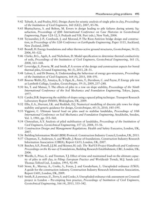
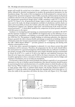
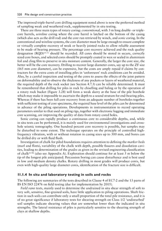
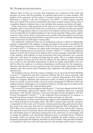
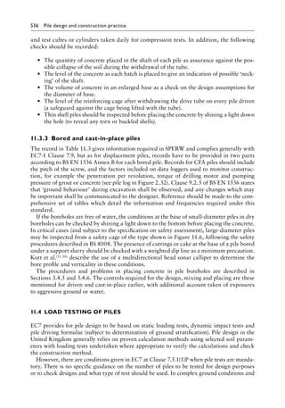
of 0.3 in heavily fissured clay. The curve for bored piles in Figure 4.8 can be used to obtain
the adhesion factor for very stiff to hard clays. Design charts for α have been based on mean
cu values obtained from unconsolidated, undrained triaxial compression tests on 38 mm sam-
ples; if other sample sizes are used or different testing methods employed, then applying the
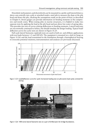
1.2
60 80 100 120
Undrained shear strength cu (kN/m2
)
Bored piles
140 160 180 200 220
1.0
0.8
0.6
0.4
0.2
Adhesion
factor
α
0
Reduced values for driven
piles where L 10B and till
is overlain by soft clay
Driven and driven and cast-in-place piles
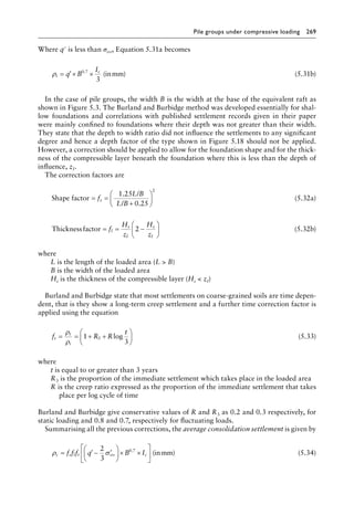
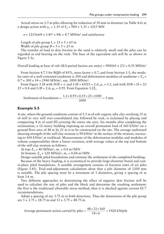
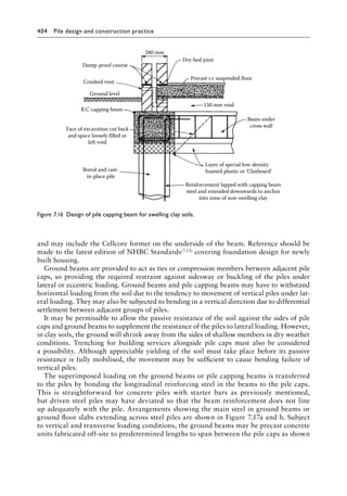
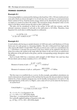
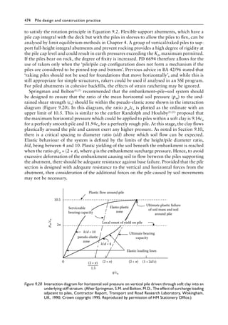
Figure 4.8╇
Adhesion factors for piles in glacial till. (After Weltman, A.J. and Healy, P.R., Piling in ‘boulder
clay’ and other glacial tills, Construction Industry Research and Information Association [CIRIA],
Report PG5, London, UK, 1978.)](https://image.slidesharecdn.com/piledesignandconstructionpracticesixtheditionpdfdrive-240129074148-da7d723b/85/Pile-Design-and-Construction-Practice-Sixth-Edition-PDFDrive-pdf-174-320.jpg)
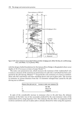
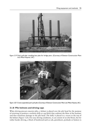
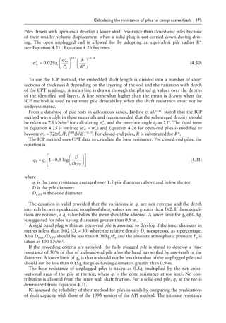
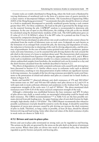
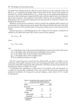
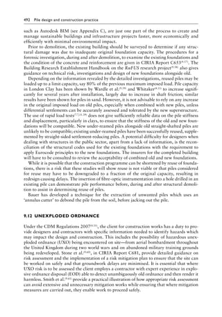
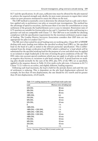
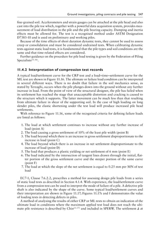
![Calculating the resistance of piles to compressive loads 171
Field trials to correlate the static cone resistance with pile loading tests are necessary in
any locality where there is no previous experience to establish the relationship between
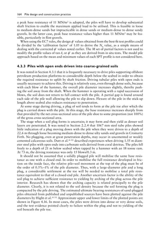
the two. In the absence of such tests, the ratio qb/qc should be taken as 0.5. The pile head
settlement at the applied load is then unlikely to exceed 10 mm for piles of base widths up
to about 500 mm. Further reductions in qb/qc values may be needed for high effective over-
burden stresses. Bustamante and Gianeselli(4.19) propose a reduction of 0.4 for driven piles
in very compact sand and gravel with a qc resistance 12 MN/m2. For larger base widths, it
is desirable to check that pile head settlements resulting from the design end-bearing pres-
sure are within tolerable limits. Pile head settlements can be calculated using the methods
described in Section 4.6.
4.3.7╇Tubular steel piles driven to deep penetration
into clays and sands
The principal users of large tubular steel piles are the offshore petroleum industry,
and recently, these piles have found increasing use as monopile foundations for off-
shore wind power generators. Guidance for engineers designing offshore piling has
been available for many years in the regularly updated recommendations of API in
RP2A WSD(4.15). (Note ISO 19902 has superseded the load and resistance factor design
[LRFD] version of API RP2A.) Their recommendations for the shaft friction of piles
in clay generally followed the αcu relationship of Semple and Rigden(4.5). Equation 4.13
was used for piles in sands with the Brinch Hansen factors of Nq for calculating base
capacity. Chow(4.40) found that the API recommendations for piles in sand were over-
conservative for short piles with L/B ratios up to 30 and for dense sands with relative
densities of 60% or more.
Research work undertaken at Imperial College, London, on the axial capacity of steel
tube piles has been referred to briefly in the preceding sections. The initial work has been
extended with analysis of further test data and has been published in book form by Jardine
et al.(4.41). The design procedures which have evolved have become known as the ICP method,
and while the following comments cover some of the salient points of research behind the
method, the reader is referred to the full ICP text for the applications. The reliability of
the method depends on continuous CPT/CPTU in situ testing and, for clays, good-quality
undisturbed samples using piston samplers and thin-walled tubes followed by sophisticated
laboratory testing using oedometer and shear ring apparatus. It is intended that the method
be used to predict pile capacities that may be mobilised during slow ML tests conducted
10 days after driving.
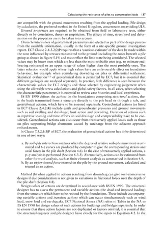
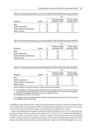
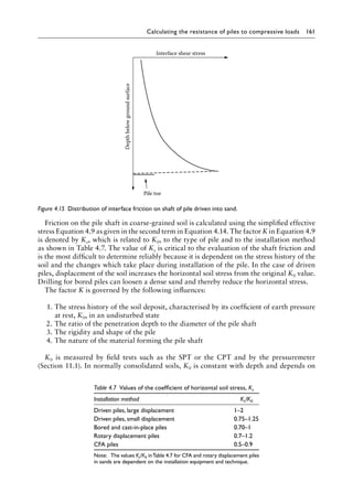
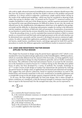
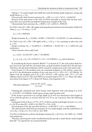
The ICP method for piles driven into clays is based on effective stresses and takes into
account the effects on the interface shaft resistance of the radial displacement of the clay
and the gross displacement of the clay beneath the base. To determine shaft resistance, the
ICP method calculates the local shear stress at failure on the interface after equalisation of
pore pressure changes brought about by the pile driving. The calculations are made for a
succession of layers over the embedded length of the shaft. They are then integrated to give
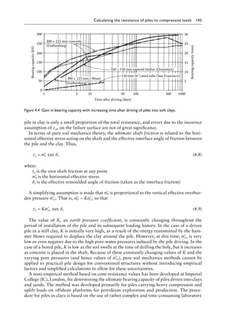
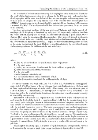
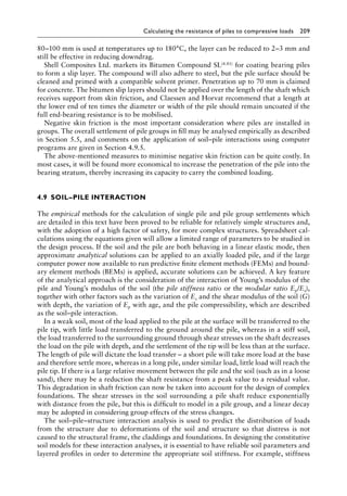
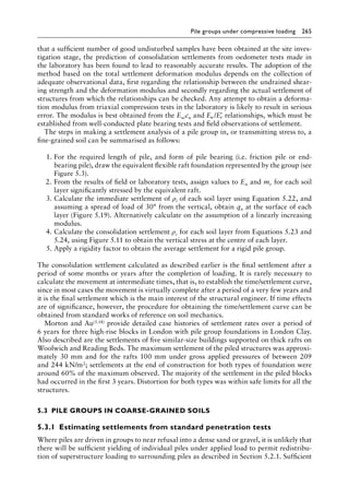
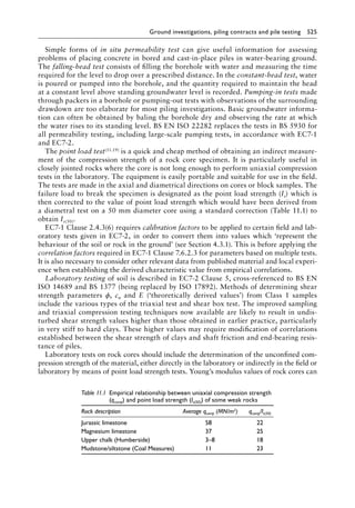
the total shaft resistance from the following equation:
Q D dZ
s f
=
∫
π τ (4.17)](https://image.slidesharecdn.com/piledesignandconstructionpracticesixtheditionpdfdrive-240129074148-da7d723b/85/Pile-Design-and-Construction-Practice-Sixth-Edition-PDFDrive-pdf-193-320.jpg)
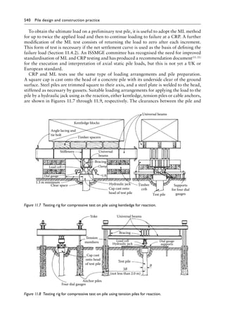
![172 Pile design and construction practice
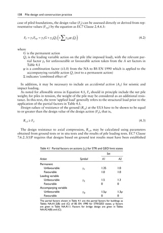
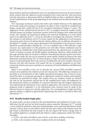
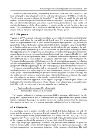
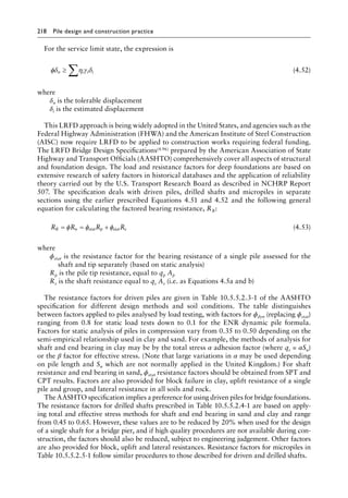
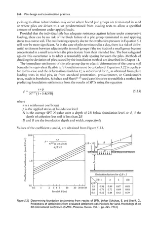
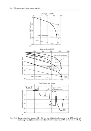
The peak local interface shear stress τf is obtained from the following equation:
τ σ δ
f
f
c
rc f
K
K
=
′ tan (4.18)
where
Kf is the coefficient of radial effective stress for shaft at failure = ′ ′
σ σ
rf vo
/
Kc is the coefficient of earth pressure at rest = ′ ′
σ σ
rc vo
/
′
σrc is the equalised radial effective stress = ′
Kc vo
σ
δf is the operational interface angle of frictional failure
Kc is obtained from the equation
K I
h
R
c vy
= +
−
2 2 16YSR 87 YSR 42
2
. . . .
.
0 0 0 0 0
0 0
− ∆ (4.19)
where
Ivy is the relative void index at yield = log10St
YSR is the yield stress ratio or apparent over-consolidation ratio
St is the clay sensitivity
h is the height of soil layer above pile toe
R is the pile radius
Kf/Kc = 0.8
An alternative to Equation 4.19 which is marginally less conservative is
K I
h
R
vo
= [ ]
−
2 625 YSR 42
2
− 0 0
0 0
. .
.
∆ (4.20)
where
Ivo is the relative void index
YSR, ΔIvy and ΔIvo are obtained either from oedometer tests in the laboratory on good-
quality undisturbed samples or from a relationship with consolidated anisotropic
undrained triaxial compression tests or by estimation from CPT or field vane tests
The clay sensitivity is determined by dividing the peak intact unconsolidated undrained
shear strength by its remoulded undrained shear strength.
The operational interface angle of friction at failure δf lies between the peak effective shear
stress angle and its ultimate or long-strain value. The actual value used in Equation 4.18 depends
on the soil type, prior shearing history and the clay-to-steel interface properties. It is influenced
by local slip at the interface when the blow of the hammer drives the pile downwards and at
rebound when the hammer is raised at the end of the stroke. A further influence is progressive
failure when the interface shear stress near the ground surface is at the ultimate state, but near
the toe, the relative pile–soil movement may be insufficient to reach the peak stress value.
The conditions at the interface can be simulated by determining δf in a ring shear appa-
ratus where the remoulded clay is sheared against an annular ring fabricated from the same
material and having the same roughness as the surface of the pile. Details of the apparatus
and the testing technique are given in the IC publication.
For calculating the shaft capacity of open-end piles in clay, an equivalent radius R* is
substituted for R in the h/R term where
R R R
outer inner
*
.
= ( )
2 2
5
−
0
(4.21)
and h/R* is not less than 8.](https://image.slidesharecdn.com/piledesignandconstructionpracticesixtheditionpdfdrive-240129074148-da7d723b/85/Pile-Design-and-Construction-Practice-Sixth-Edition-PDFDrive-pdf-194-320.jpg)
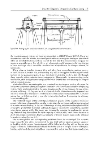
![Calculating the resistance of piles to compressive loads 173
Dealing with the base resistance of closed-end piles in clay, the ICP method does not accept
the widely used practice of calculating the ultimate resistance from Qb = NccuAb where the bear-
ing capacity factor Nc is assumed to be equal to 9. The database of instrumented pile tests used
in the IC research showed a wide variation in Nc which was found to be higher than 9 in all
the tests analysed. However, the results did demonstrate a close correlation with the results of
static cone penetration tests and led to a recommendation to adopt the following relationships:
q q
b c
= 0.8 for undrained loading (4.22)
and
q q
b c
= 1 3 for drained loading
. (4.23)
The cone resistance qc is obtained from CPT’s by averaging the readings over a distance
of 1.5 pile diameters above and below the toe.
For open-end piles, plugging of the pile toe with clay is defined as the stage when the plug
is carried down by the pile during driving. This is deemed to occur when [Dinner/DCPT +
0.45qc]/Pa is less than 36. The cone diameter DCPT is 0.038 m and the normalised atmo-
spheric pressure Pa is 100 kN/m2.
Fully plugged piles as defined above develop half the base resistance calculated by
Equations 4.22 and 4.23 for undrained and drained loadings respectively, after a pile head
displacement of D/10.
The base resistance of an unplugged open-end pile is calculated on the annular area of steel
only. The IC proposed 1.6 increase in the value of Qb for drained loading when qb is taken as the
average qc at founding depth would seem to be optimistic when compared with Equation 4.23.
Jardine et al.(4.41) recommend safety factors of 1.3–1.6 for the shaft resistance in compres-
sion for offshore foundations where uniform settlement of the structure is not critical and
the design is based on allowable stress methods.
The ICP method of design for tubular piles in sands is a simple one based on CPTs. No
other field work or special laboratory testing is required where correlations are available,
such as the Chow(4.40) data for the shear modulus. The method is wholly empirical based on
small-diameter un-instrumented loading tests and experience. It is justified by the assump-
tion that the penetration of the sleeved cone simulates the displacement of the soil by a
closed-end or fully plugged pile.
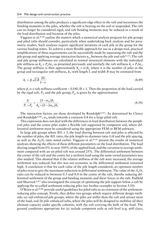
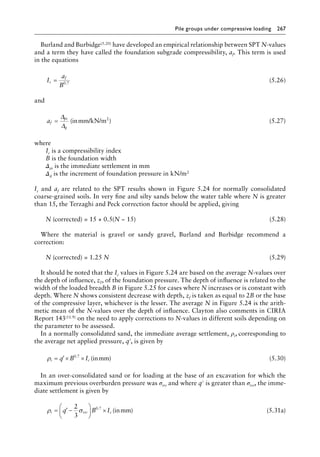
The expression for the shaft resistance is calculated by the following sequence of equations:
Unit shaft resistance = = ′
τ σ δ
f rf f
tan (4.24)
Radial effective stress at point of shaft failure = ′ = ′ + ′
σ σ σ
rf rc rd
∆ (4.25)
Equalised radial effective stress = ′ =
′
σ
σ
rc c
vo
a
q
P
0 029
0 1
.
. 3
3 0 38
h
R
− .
(4.26)
Distant increase in local radial effective stress = ′ =
∆σ
δ
rd
f
G
R
2
(4.27)
where
δf = δcr is the interface angle of friction at failure
R is the pile radius
G is the operational shear modulus](https://image.slidesharecdn.com/piledesignandconstructionpracticesixtheditionpdfdrive-240129074148-da7d723b/85/Pile-Design-and-Construction-Practice-Sixth-Edition-PDFDrive-pdf-195-320.jpg)
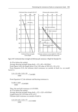
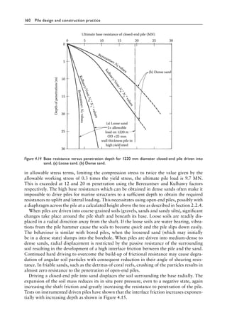
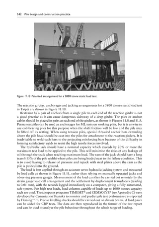
![234 Pile design and construction practice
Example 4.8
A tubular steel pile with an OD of 1067 mm is driven with a closed end to near refusal
in a moderately strong sandstone (average quc = 20 MN/m2) overlain by 15 m of soft clay.
Core drilling in the rock showed a fracture frequency of 5 joints per metre. Calculate the
maximum load (permanent unfavourable action) which can be applied to the pile and the
settlement at this load.
Only a small penetration below rockhead will be possible with sandstone of this quality,
and the rock will be shattered by the impact. Hence, frictional support both in the soft
clay and the rock will be negligible compared with the base resistance.
Pile-driving impact is likely to open joints in the rock; hence, the base resistance should
not exceed the unconfined compression strength of the intact rock:
From Section 7.10, NEd/NRd ≤ 1.0
NEd = Gk × γG = Gk × 1.35
NRd = Afy/γM0
Using S235 JRH tubular steel pile with wall thickness of 19 mm, characteristic yield strength
of 235 N/mm2, and γM0 = 1.0, then NRd = [(10672 − 10292) × 235 × π/4]/1.0 × 106 = 14.7 MN.
Hence, the maximum load based on steel strength Gk = 14.7/1.35 = 10.9 MN.
If the characteristic pile resistance Rck is equal to the base resistance with γRd = 1.4, then
Rbk = (1.0672 × π/4 × 20)/1.4 = 12.7 MN.
For DA1-1 (sets A1 + M1 + R1 apply) for a driven pile, if the partial factors are γb = 1 and
γG = 1.35, then Rcd = 12.7/1.0 = 12.7 MN Fd = 1.35 × 10.9 = 14.7 MN which fails.
For DA1-2 (sets A2 + M1 + R4), if the partial factors are γb = 1.7 (no pile testing) and
γG = 1.0, then Rcd = 12.7/1.7 = 7.5 MN.
This is the maximum unfavourable action which the pile can resist and will satisfy DA1-1:
Fd = 1.35 × 7.5 = 10.13 MN Rcd = 12.7 MN
Pile-driving impact may increase the fracture frequency from 5 to 10, say, fractures per
metre giving a mass factor of 0.2. From Section 5.4, the modulus ratio of sandstone is 300:
Deformation modulus MN/m2
= × × =
0 2 300 20 1200
.
From Equation 4.35,
Settlement of pile head =
× ×
× ×
+
× ×
7 52 15 1000
0 0626 2 10
0 5 7 52 100
5
.
.
. . 0
0
1 067 1200
9 0 2 9
11 9
.
. .
.
×
= +
= mm
(Range is likely to be from 10 to 15 mm.)
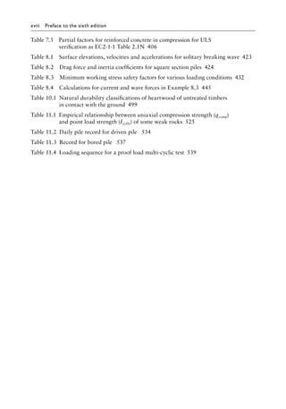
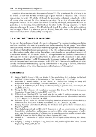
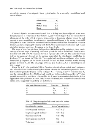
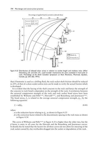
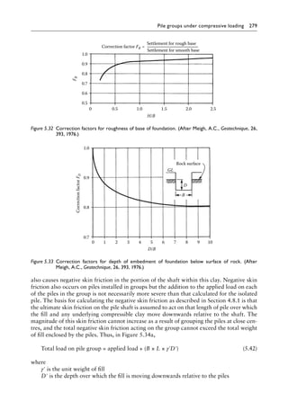
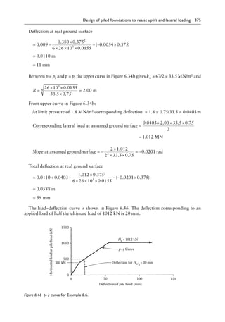
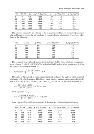
Example 4.9
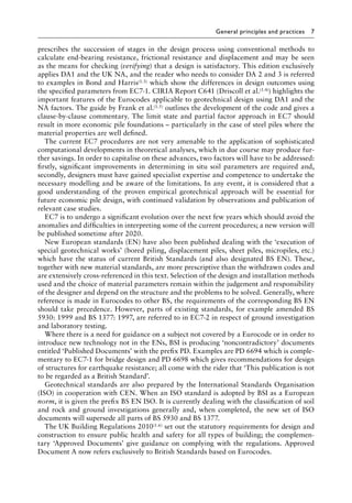
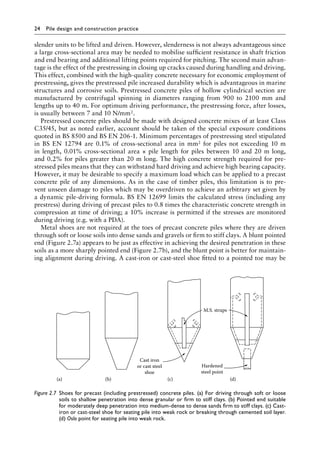
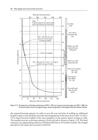
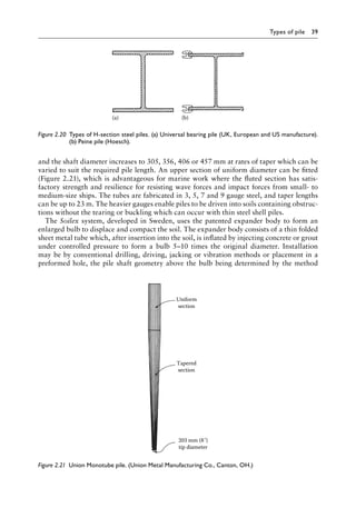
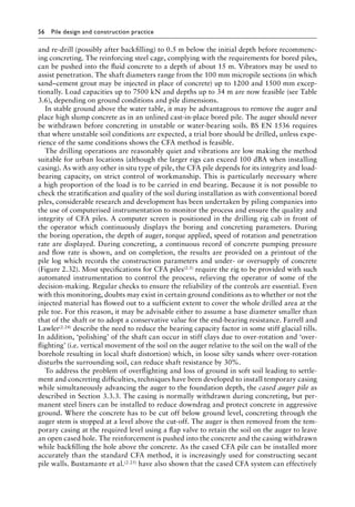
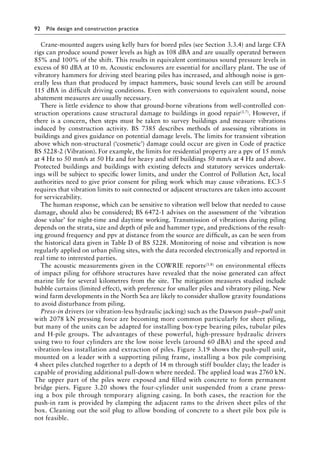
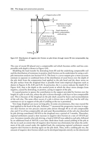
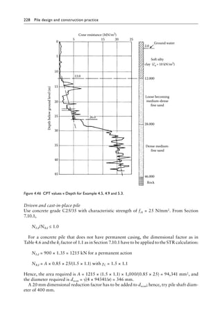
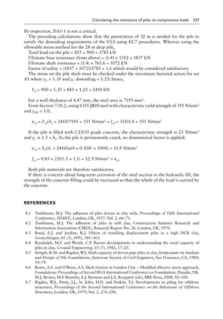
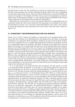
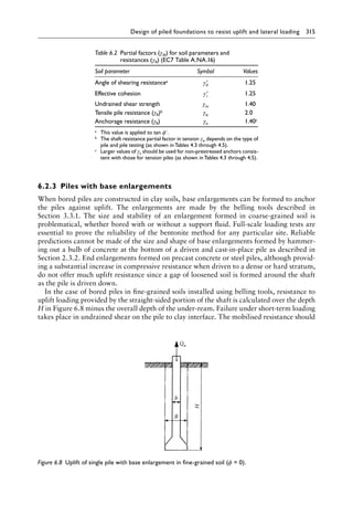
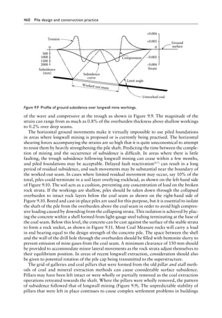
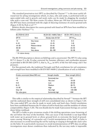
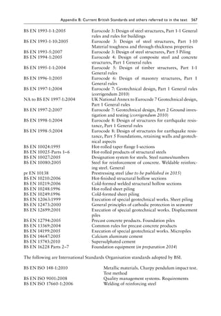
A 5 m layer of hydraulic fill consisting of sand is pumped into place over the ground shown
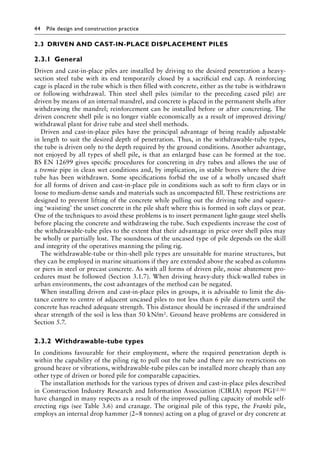
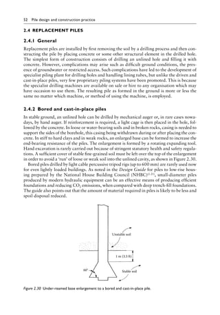
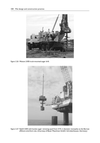
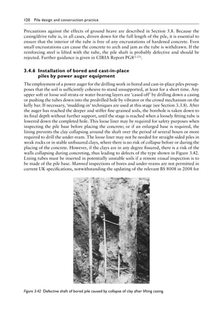
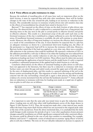
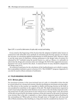
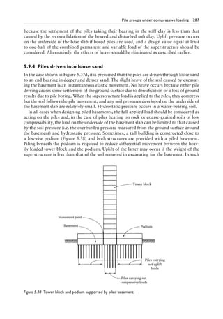
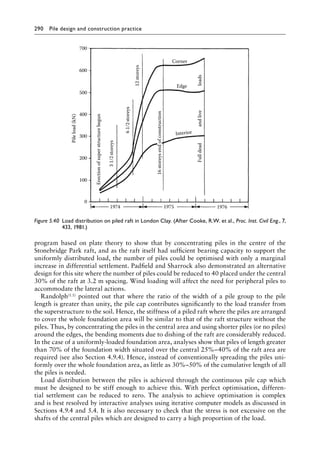
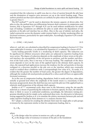
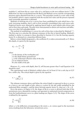
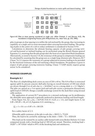
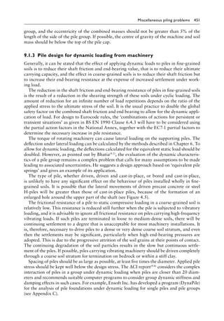
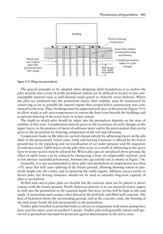
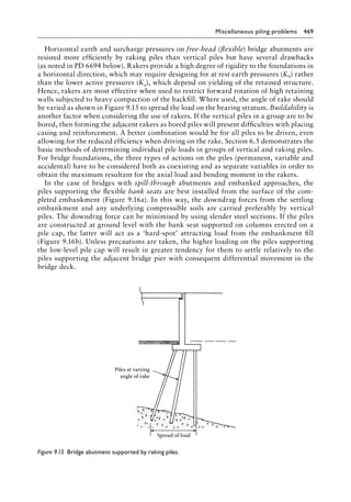
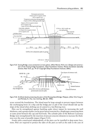
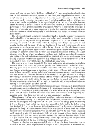
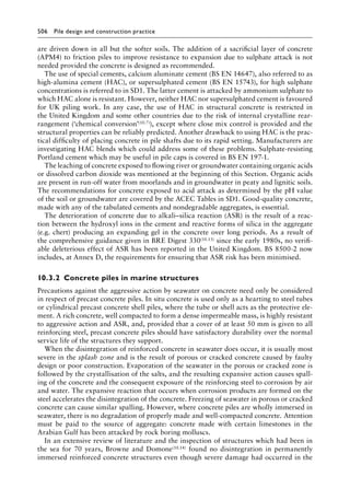
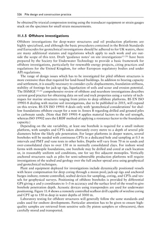
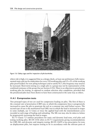
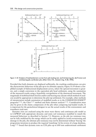
in Figure 4.46. The calculated time/settlement curve for the surface of the hydraulic fill is](https://image.slidesharecdn.com/piledesignandconstructionpracticesixtheditionpdfdrive-240129074148-da7d723b/85/Pile-Design-and-Construction-Practice-Sixth-Edition-PDFDrive-pdf-256-320.jpg)
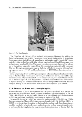
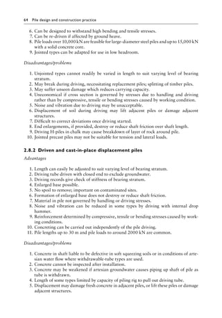
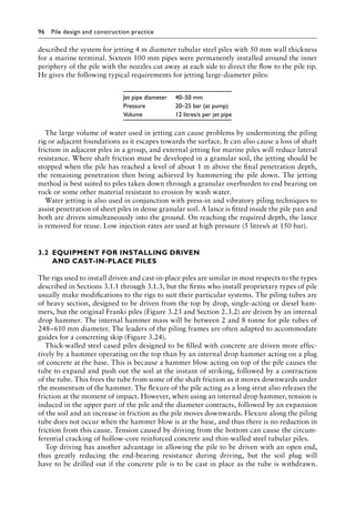
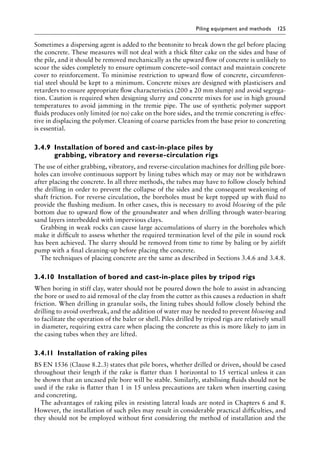
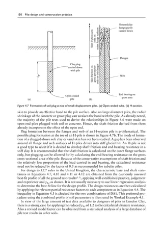
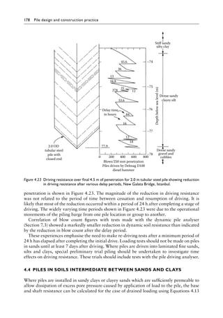
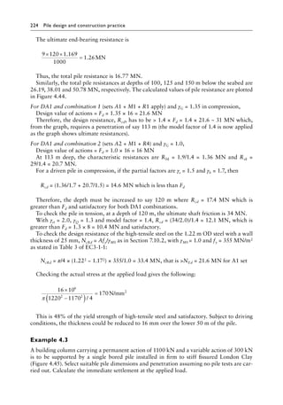
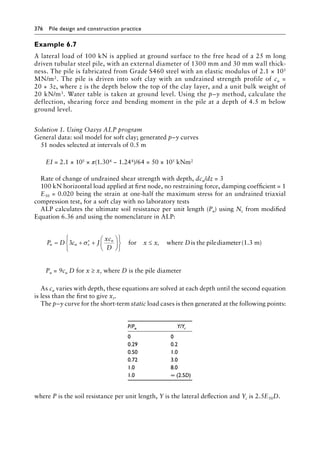
![Calculating the resistance of piles to compressive loads 235
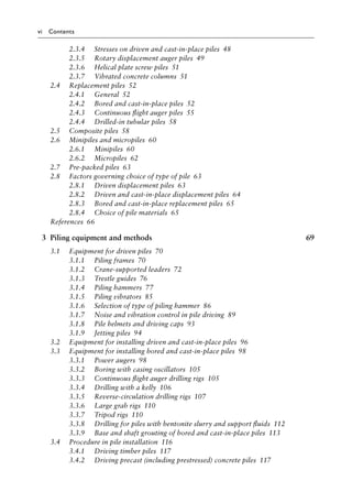
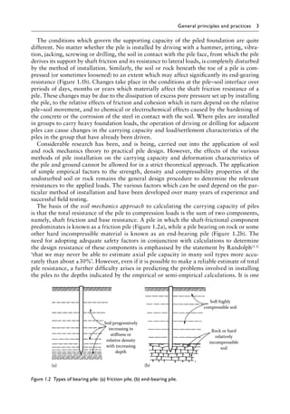
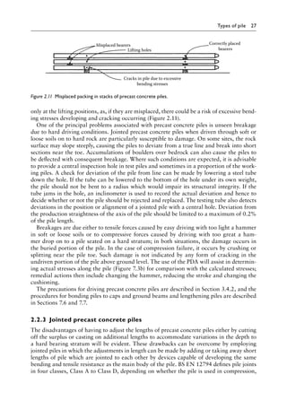
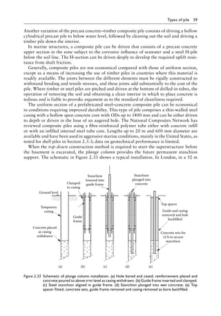
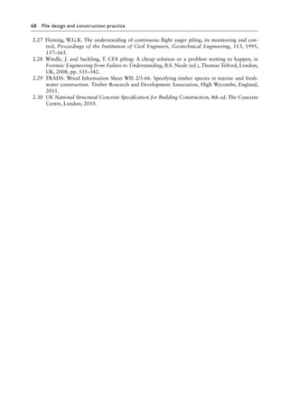
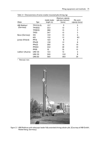
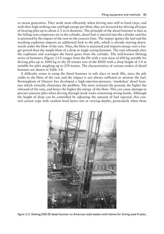
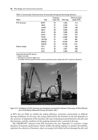
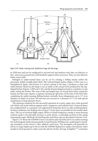
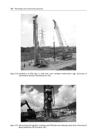
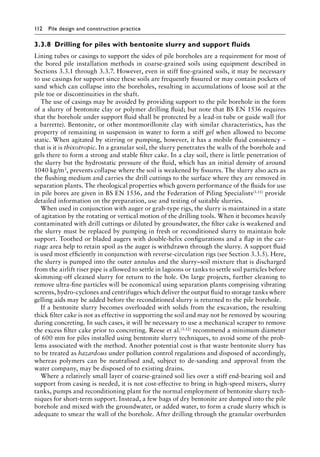
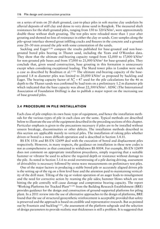
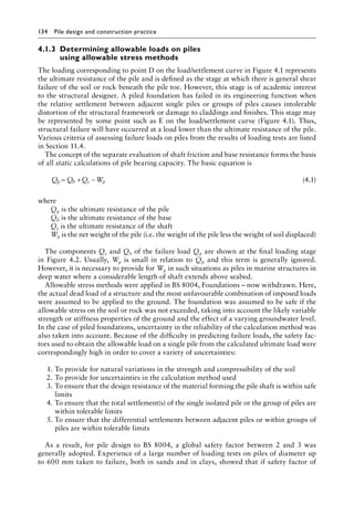
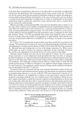
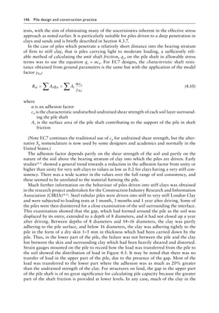
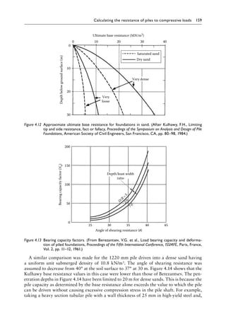
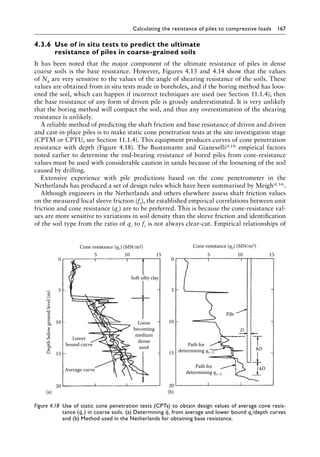
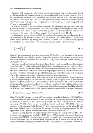
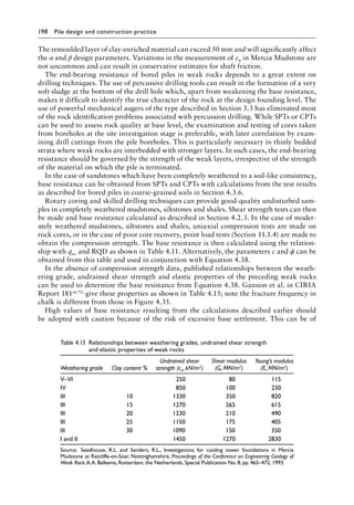
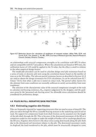
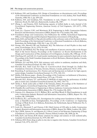
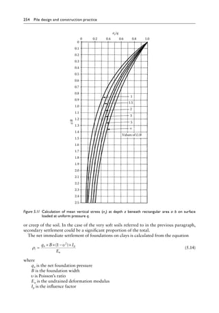
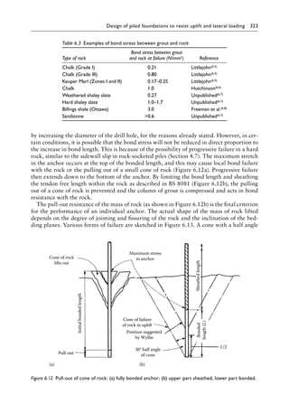
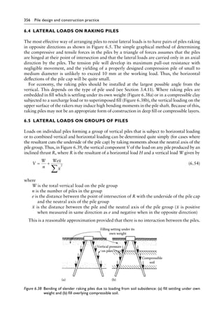
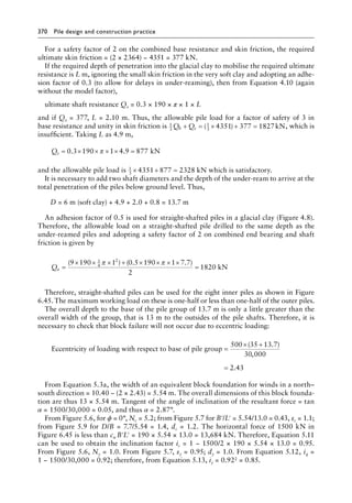
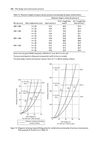
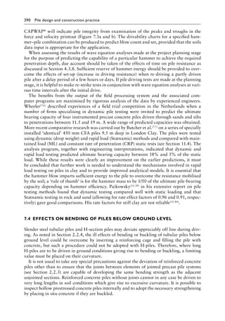
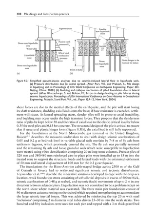
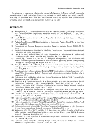
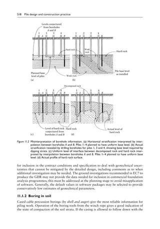
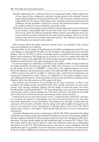
shown in Figure 4.48. Two years after the completion of filling, a closed-end steel cased pile
with an OD of 517 mm is driven to a penetration of 27 m to carry a permanent (unfavour-
able) load of 900 kN. Calculate the negative friction which is developed on the pile shaft,
and assess whether or not any deeper penetration is required to carry the combined load and
negative skin friction.
It can be seen from the time/settlement curve that about 120 mm of settlement will take
place from the time of driving the pile until the clay beneath the fill layer is fully consoli-
dated. This movement is considerably larger than the compression of the pile head under
the applied load (about 10 mm of settlement would be expected under the applied load of
900 kN). Therefore, negative skin friction will be developed over the whole depth of the
pile within the hydraulic fill. Considering now the negative skin friction within the soft clay,
if it is assumed that downdrag will not occur if the clay settles relatively to the pile by less
than 5 mm, then adding the settlement of the pile toe (10 mm at the applied load) negative
skin friction will not be developed below the point where the clay settles by less than 15 mm
relative to site datum. After pile driving, the full thickness of the clay settles by 120 mm at
the surface of the layer. By simple proportion, a settlement of 5 mm occurs at a point 12 ×
15/120 = 1.5 m above the base of the layer. This assumes uniform compressibility in the
clay, but there is decreasing compressibility with increasing depth such that the settlement
decreases to less than 15 mm at a point not less than 2 m above the base of the layer. A closer
estimate could be obtained by a t–z analysis. However, the above approximate assessment
will be adequate for the present case.
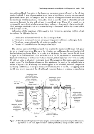
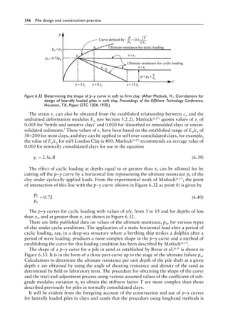
Adopting Meyerhof’s factor from Figure 4.39 for the negative skin friction and applying
Equation 4.46 gives the following:
The unit negative skin friction 2 m above the base of clay layer is
0.3 ′
σvo = 0.3 × 9.81[(5 × 2) + (2 × 1.9) + (8 × 0.9)] = 62 kN/m2
The unit negative skin friction at the top of clay stratum is
0.3 × 9.81 × 5 × 2 = 29 kN/m2
The unit negative skin friction 2 m below the top of clay stratum (at groundwater level) is
0.3 × 9.81 [(5 × 2) + (2 × 1.9)] = 41 kN/m2
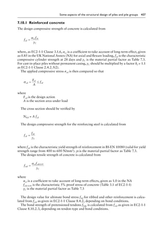
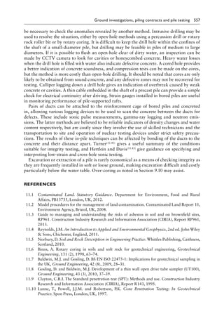
Completion of
hydraulic fill
Commencement
of piling
Time in years
2.0
120 mm
450 mm
670 mm
Settlement
in
mm
load
from
fill
(kN/m
2
) 0.5
0
Calculated ‘final’
settlement
Figure 4.48╇ Settlement v Time for Example 4.9.](https://image.slidesharecdn.com/piledesignandconstructionpracticesixtheditionpdfdrive-240129074148-da7d723b/85/Pile-Design-and-Construction-Practice-Sixth-Edition-PDFDrive-pdf-257-320.jpg)
![236 Pile design and construction practice
The total negative skin friction in clay is
π × 0.517 [0.5(29 +41)2 + 0.5(41 + 62)8] = 783 kN
Drainage of the fill will produce a medium-dense state of compaction for which K0 is 0.45
and Ks in Equation 4.14 is 0.67 (Table 4.7) and δ = 0.7 × 30 = 21° (Table 4.8). Therefore, the
additional negative skin friction as in Equation 4.14 is
0.67 × (9.81 × 2 × 5) × 0.5 × tan 21° × π × 0.517 × 5 = 102 kN
Hence, the total negative skin friction on pile (dragload) DGd = 102 + 783 = 885 kN.
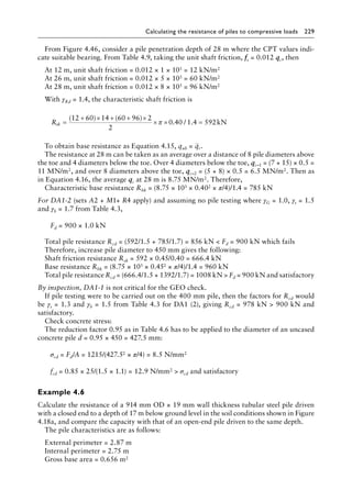
From Example 4.5, the average CPT resistance at a penetration of 28 m is about
8.75 MN/m2, and applying the model factor γRd = 1.4 as the resistances have been calcu-
lated from the cautious estimate of CPT results and pile tests is not practical in downdrag
conditions; then
Characteristic base resistance at 28 m = Rbk = (π/4 × 0.5172 × 8.75 × 103)/1.4 = 1312 kN
Also from Example 4.5 by proportion,
Characteristic shaft friction resistance from 12 to 28 m = Rsk = 666.4 × 517/450 = 765.6 kN
The shaft resistance is fully mobilised over the depth below the base of the fill.
For DA1-2, the partial factors are as Table 4.17 for sets A1 + M1 in downdrag with Table
4.3 R4 resistance factors:
Structural action, A1 = 1.0. Downdrag action, A1 = 1.25. R4 set, γs = 1.5 γb = 1.7
Design value of actions Fd = 900 × 1.0 + 885 × 1.25 = 2006 kN
Design resistance Rcd = Rcs + Rcb = (765.6/1.5 + 1312/1.7) = 1282 kN Fd which fails
Therefore, the pile has to be driven a further 4 m to 32 m depth in order to support the
dragload:
At 32 m depth, the average qc from Figure 4.46 and Equation 4.16 is approximately
12 MN/m2. The characteristic base resistance at 32 m is Rbk = (π/4 × 0.5172 × 12 × 103)/1.4 =
1799 kN.
At 30 m depth, the cone resistance qc = 16 MN; hence, the unit shaft resistance is 0.012 ×
16 × 1000 = 192 kN/m2.
At 32 m depth, qc = 19 MN; hence, the unit shaft resistance is 0.012 × 19 × 1000 =
228 kN/m2.
The increase in total shaft friction over the extra 2 m to 30 m depth is
( )
.
96 192 2
2
0 517 468
+
× × =
π kN
The increase in total shaft friction over extra 2–32 m is
( )
.
192 228 2
2
0 517 682
+
× × =
π kN
The characteristic shaft friction resistance from 12 to 32 m is Rsk = 765.6 + (468 +
682)/1.4 = 1587 kN.
The design resistance is Rcd = Rcs + Rcb = (1587/1.5 + 1799/1.7) = 2116 kN Fd = 2006 kN
which is therefore satisfactory.](https://image.slidesharecdn.com/piledesignandconstructionpracticesixtheditionpdfdrive-240129074148-da7d723b/85/Pile-Design-and-Construction-Practice-Sixth-Edition-PDFDrive-pdf-258-320.jpg)

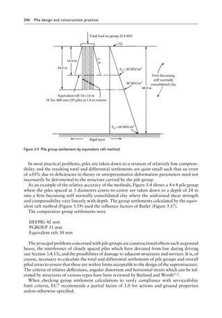
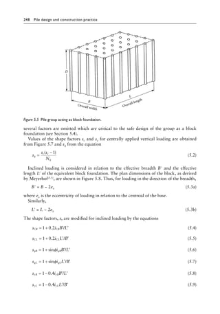
![Pile groups under compressive loading 247
5.2╇ PILE GROUPS IN FINE-GRAINED SOILS
5.2.1╇ Ultimate bearing resistance
Burland(5.3) has stated his strong opinion that specifying authorities’ requirement for each
pile in a group to be designed to carry an applied load which has a global safety factor on
its ultimate bearing capacity can result in grossly uneconomic foundation design. This is
because it ignores the capability of a raft to redistribute loads from the superstructure on to
the piles forming the group. Redistribution of loading can be permitted provided that
1. The raft has sufficient flexibility (ductility) to perform this function without failure as
a structural unit
2. The superstructure has sufficient flexibility to accommodate any resulting movements
in the raft
3. The pile group has adequate resistance against failure or excessive settlement when
considered as an equivalent block foundation
4. Account is taken of the effects of ground heave or subsidence of the mass of soil
encompassed by the pile group during the construction stage (Section 5.7)
Burland recommends that redistribution should be effected by permitting piles carrying the
heavier loading to mobilise their ultimate resistance in shaft friction, thereby yielding and
transferring some of their load to surrounding piles within the group. This concept of duc-
tile foundations where load sharing is designed between raft and piles and from pile to pile
is discussed further in Section 5.10.
In all cases where piles are designed to transmit loading as a group terminating in a clay
or sand stratum, whether or not some of the piles are permitted to yield, it is essential to
consider the risks of general shear failure or excessive total and differential settlement of the
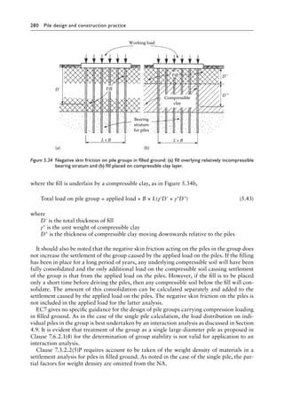
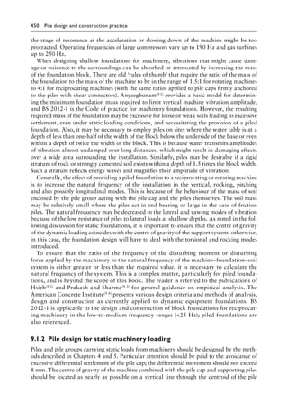
equivalent block foundation taking the form shown in Figure 5.5.
The bearing resistance (ultimate limit state [ULS]) of the block foundation as shown in
Figure 5.5 can be calculated by using the Brinch Hansen general equation(5.4). This was
referred to in Section 4.3 with reference to the bearing capacity factor Nq in Equation 4.13.
The complete Brinch Hansen equation as applied to a shallow spread foundation embedded
in soil with a level ground surface is
q cN s d i b p N s d i b BN s d i b
u c c c c c o q q q q q
= + + 0 5
. γ γ γ γ γ γ (5.1)
where
c is the cohesion intercept of soil
Nc, Nq and Nγ are bearing capacity factors
sc, sq and sγ are shape factors
dc, dq and dγ are depth factors
ic, iq and iγ are load inclination factors
bc, bq and bγ are base inclination factors
γ is the density of the soil
po is the pressure of the overburden soil at foundation level
For undrained conditions (ϕ = 0°), the second term of the equation is omitted and cu is sub-
stituted for c. For drained conditions, c′ (the cohesion intercept in terms of effective stress) is
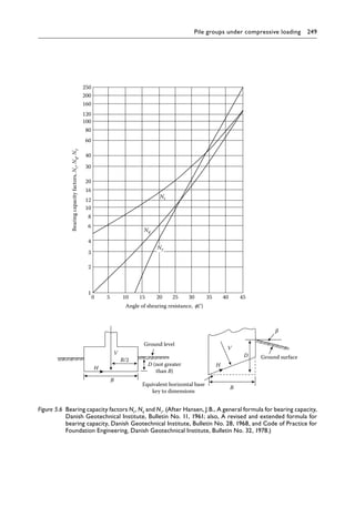
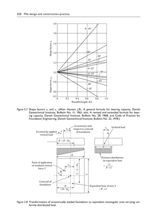
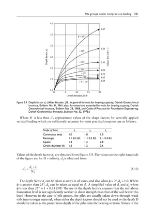
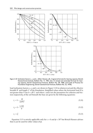
used instead of c. Values of the factors in Equation 5.1 are shown in Figures 5.6 through 5.10.
The equation in similar form is given in EC7 Annex D for drained bearing resistance, but
as this is essentially an expression for shallow spread foundations (D not greater than B),](https://image.slidesharecdn.com/piledesignandconstructionpracticesixtheditionpdfdrive-240129074148-da7d723b/85/Pile-Design-and-Construction-Practice-Sixth-Edition-PDFDrive-pdf-269-320.jpg)
![Pile groups under compressive loading 295
The weight of the pile group above seabed level (with concrete weight density 2.5 tonne/m3)
is as follows:
= × × ×
[ ]+ × × + ×
[ ]
{ }
( )=
9 81 10 5 9 0 1 25 2 5 42 0 45 12 1 5 4 2 5 52
2
. . . . . . ( . ) ( . ) 3
33 kN
Check resistance of single pile
From Example 4.4, characteristic shaft friction resistance for a 7 m penetration by compari-
son is
Rsk = 379 × 7/8.5 = 312 kN and characteristic end bearing is
Rbk = 289.3 × 7/8.5 = 238 kN
For DA1 combination 2 (driven pile), γb = 1.7, γs = 1.5 and γRd = 1.4, and for actions
γG = 1.0 and γQ = 1.3,
Permanent action = (3000 + 5233)/42 = 196 kN/pile
Variable action = 3000/42 = 71 kN/pile
Fd = 196 × 1.0 + 71 × 1.3 = 288 kN
Rcd = (238/1.7 + 312/1.5) = 348 kN Fd and satisfactory
For DA1 combination 1 (driven pile), γb = 1.0, γs = 1.0 and γRd = 1.4, and for actions
γG = 1.35 and γQ = 1.5,
Fd = 1.35 × 196 + 71 × 1.5 = 372 kN
Rcd = (238/1.0 + 312/1.0) = 550 kN Fd and satisfactory
Check settlement of pile group
Because the piles are driven into a uniform sand carrying their load partly in skin friction
and partly in end bearing, the distribution of load shown in Figure 5.3a applies:
Depth below seabed to equivalent raft m
= × =
2
3
7 4 67
.
Thus, the dimensions of the equivalent raft are
L
B
= + × ×
( ) =
= + × ×
( ) =
8 1 2 4 67 10 4
6 75 2 4 67 9 1
1
4
1
4
. . .
. . .
m
m
In calculating settlements, it is only necessary to consider the unfactored actions from the
bulk-handling plant. The piles and pile cap settle immediately as they are constructed and
the pile cap is finished to a level surface:
Pressure on sand below raft kN/m2
=
×
×
=
6 1000
10 4 9 1
63
. .
At level of raft, effective overburden pressure = × ×
1 2 9 81 4
. . .
.67 55
= kN/m2
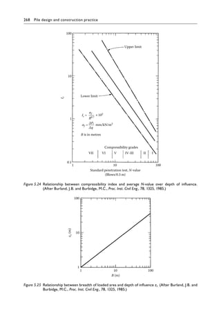
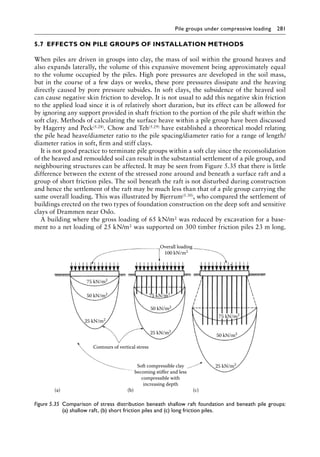
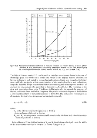
From Figure 5.24 for an SPT N-value of 15 blows/300 mm, Ic is 4 × 10–2.](https://image.slidesharecdn.com/piledesignandconstructionpracticesixtheditionpdfdrive-240129074148-da7d723b/85/Pile-Design-and-Construction-Practice-Sixth-Edition-PDFDrive-pdf-317-320.jpg)
![298 Pile design and construction practice
For axisymmetric loading (L/B = 1) from Equation 5.35, uncorrected settlements are
given by
Layer1 mm
Layer
=
× × ×
×
=
=
× × ×
278 0 20 6 1000
12 5 1000
27
2
278 0 36 5 2 10
.
.
. . 0
00
40 1000
13
3
278 0 46 2 5 1000
50 1000
6
3
×
=
=
× × ×
×
=
mm
Layer a mm
Layer b
. .
=
=
× × ×
×
=
=
278 0 4 10 3 1000
50 1000
23
69
. .
mm
Total mm
Similarly, for L/B 10, the uncorrected settlements are
Layer1 mm
Layer2 mm
Layer3 mm
Total 49 mm
=
=
=
=
19
9
21
By interpolation, the settlement for L/B = 1.3 is 66 mm.
Effective overburden pressure at base of raft
= × + × + × =
9 81 2 1 9 10 0 9 10 0 9 214
5 3
2
. [( . ) ( . ) ( . )] kN/m
.
From Equation 6
6 1 0 5
214
278
0 62
5 37 1 0 2
25
0 1
1
2
, .
, .
.
C
C lg
= − × =
= + =
.
.
From Equation 1
1 48
.
Corrected settlement at 25 years = 0.62 × 1.48 × 66 = 61 mm, say, between 50 and 70 mm.
Example 5.4
Nuclear reactors and their containment structures and ancillary units weighing 900 MN
are to be constructed on a base 70 × 32 m sited on 8 m loose to medium-dense sand overly-
ing a moderately strong sandstone. Rotary cored boreholes showed that below a thin zone
of weak weathered rock, the RQD value of the sandstone was 85% and the average uncon-
fined compression strength was 14 MN/m2. For this loading, a piled foundation is required
using 1.5 m diameter bored piles taken 2 m below weak weathered rock on to the moder-
ately strong sandstone. Calculate the concrete stress and settlement of a group of 84 piles
arranged in 14 rows of six piles each at 5 m centres in both directions.
Use class C25/30 concrete with γC = 1.5 × 1.1:
Design concrete compressive strength = 0.85 × 25/(1.5 × 1.1) = 12.9 MN/m2](https://image.slidesharecdn.com/piledesignandconstructionpracticesixtheditionpdfdrive-240129074148-da7d723b/85/Pile-Design-and-Construction-Practice-Sixth-Edition-PDFDrive-pdf-320-320.jpg)
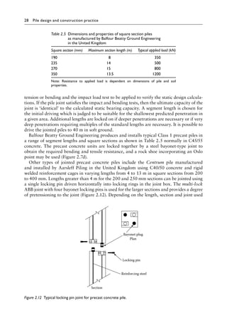
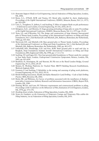
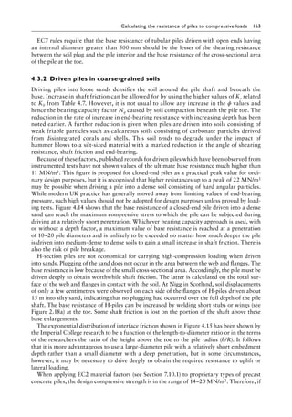
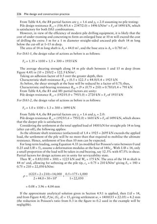
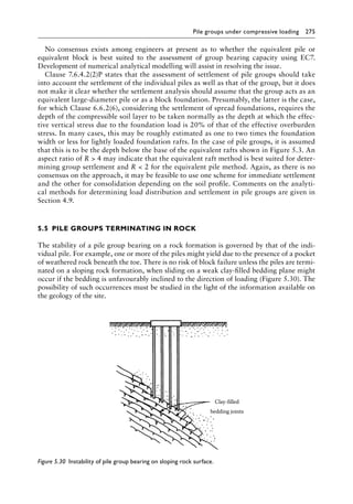
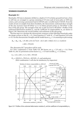
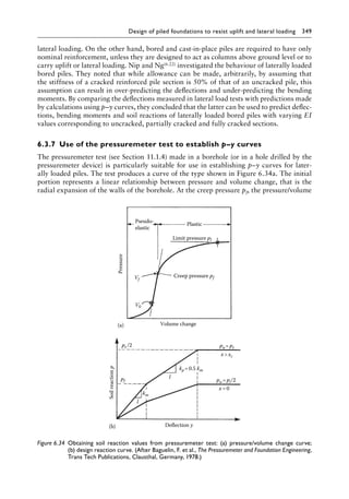
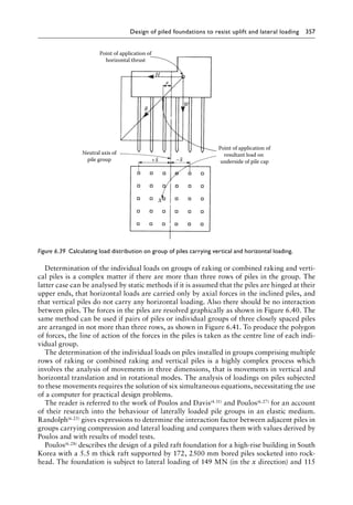
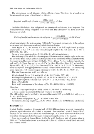
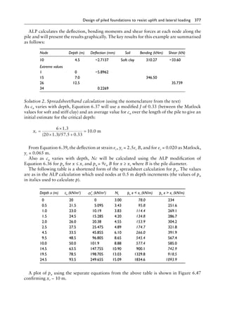
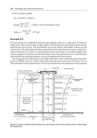
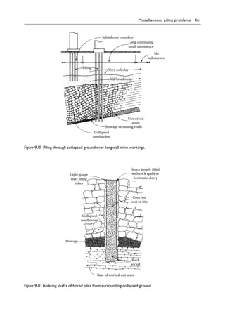
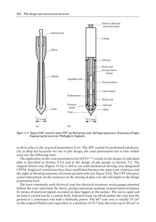
![300 Pile design and construction practice
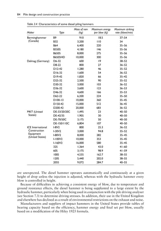
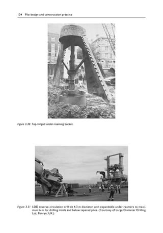
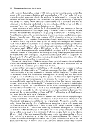
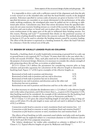
The central two rows of piles carry higher loads than the outer two rows on each side.
A likely loading for the centre rows is 2200 kN per pile. The required penetration of the
piles will be calculated on this loading. The exterior piles will be taken to the same depth
but adopting a reduced diameter as required by the lesser loading.
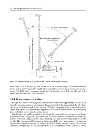
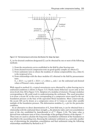
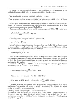
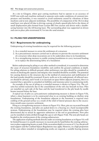
The piles carry negative skin friction due to the consolidation of the soft clay under the
imposed loading of the sand fill. At 6 months, settlement of the soft clay will be continuing
at a very slow rate and it is appropriate to use Figure 4.39 (Meyerhof) to calculate the nega-
tive skin friction in this layer.
Unit negative skin friction at top of layer
= ′ = × × × =
0 30 0 30 9 81 2 1 4 24 7
. . . . .
σvo kN/m2
Unit negative skin friction at groundwater level (see Figure 5.43)
= × × + × =
0 30 9 81 2 1 4 1 6 3 38 8
. . [( . ) ( . )] . kN/m2
1200 mm bored
piles
0.00
9.50
10.5
m
16.50
12-storey building
Ground level
GWL
7.00
Soft organic
silty clay
Sand fill (γ=2.1 Mg/m3
)
3.75
Stiff to very
stiff clay
30°
L =52.25
B =22.25
23.50
30.50
37.50
44.50
Cu =430 kN/m2
mv=0.04 m2
/MN
Ed =120 MN/m2
Cu =90 kN/m2
mv =0.08 m2
/MN
Layer 2
Layer 3
Layer 4
Rock
L=60.25
L =68.25
L=76.25
B=38.25
B=46.25
B =30.25
qn=139 kN/m2
4.00
Ed =40 MN/m2
(γsat=1.6 Mg/m3
)
48.75×18.75
σ
Figure 5.43╇
Pile group and stratification for Example 5.5.](https://image.slidesharecdn.com/piledesignandconstructionpracticesixtheditionpdfdrive-240129074148-da7d723b/85/Pile-Design-and-Construction-Practice-Sixth-Edition-PDFDrive-pdf-322-320.jpg)
![Pile groups under compressive loading 301
Unit negative skin friction at bottom of layer
= × × + × + × =
0 30 9 81 2 1 4 1 6 3 0 6 2 5 43 3
. . [( . ) ( . ) ( . . )] . kN/m2
Therefore, total negative skin friction in soft clay
= × + × + + ×
=
π 1 2 24 7 38 8 3 28 8 43 3 2 5 746
1
2
1
2
. ( . . ) ( . . ) . kN
Because the pile will settle due to yielding of the stiff clay when the full load is applied,
the pile will move downwards relative to the lower part of the soft clay. Thus, negative skin
friction will be developed only over about 80% of the length within the soft clay. Thus,
approximate total negative skin friction in soft clay = 0.8 × 746 = 597 kN.
The negative skin friction in the sand can be calculated using the coefficients for Ks in
Table 4.7. Although the compacted sand fill is dense, it will be loosened by pile boring to
give a coefficient Ks of 1 and a ϕ value of 30°. From Equation 4.14 using average overburden
pressure (but ignoring the γRd factor for allowable stress application),
Negative skin friction on pile in sand fill
= 0.5 × 1 × 9.81 × 2.1 × 4 × tan 30° × π × 1.2 × 4 = 359 kN
Total negative skin friction on pile = 359 + 597 = 956 kN
Total applied load on piles in centre rows = 956 + 2200 = 3156 kN
The required pile penetration depth is calculated on the basis of the building loading,
with a check being made to ensure that the safety factor on the combined building load and
negative skin friction is adequate.
Required ultimate pile resistance for overall safety factor of 2 (Section 4.6) = 2 × 2200 =
4400 kN.
Take a trial penetration depth of 10 m into the stiff clay stratum. At the pile base level,
cub = 190 kN/m2 and the average value of cu on the shaft is 140 kN/m2. Thus,
Ultimate base resistance kN
Load to be
= × × × × =
1
4
2
1 2 9 190 1935
π .
c
carried in skin friction N
= − =
4400 1935 2465
The adhesion factor for a straight-sided pile can be taken as 0.45. Therefore, from
Equation 4.10 (and again ignoring the γRd factor for allowable stress application),
Total load to be resisted by the pile shaft = 2465 = 0.45 × 140 × π × 1.2 × l
from which l = 10.4 m (say 10.5 m) and the trial depth is satisfactory.
Checking the criterion of a safety factor of 3 in end bearing and unity in skin friction,
allowable load = × + =
( )
1
3
1935 2465 3110 kN which roughly equals the building load plus
the negative skin friction. Checking the overall safety factor on the combined loading,
Safety factor (1935 + 2465)/3156 = 1.4](https://image.slidesharecdn.com/piledesignandconstructionpracticesixtheditionpdfdrive-240129074148-da7d723b/85/Pile-Design-and-Construction-Practice-Sixth-Edition-PDFDrive-pdf-323-320.jpg)
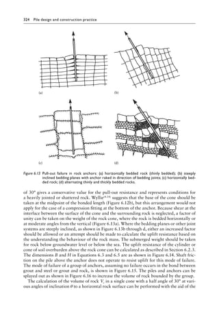
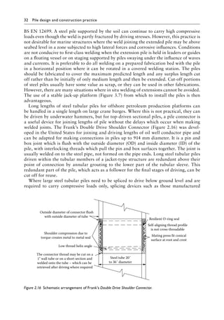
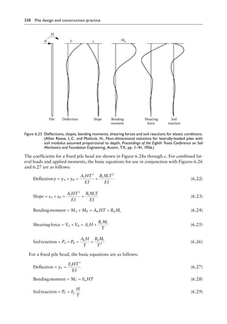
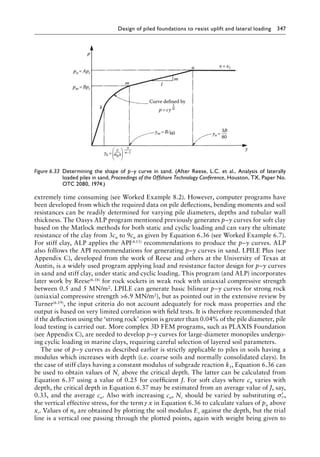
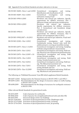
![Design of piled foundations to resist uplift and lateral loading 327
EC7 Clause 8.1.1(4)P requires tension piles to be designed as described in Section 7 of the
code. EC7 is not appropriate for anchorages formed by grouting tendons into drilled holes
and requires their design and installation to be in accordance with BS EN 1537.
BS EN 1537 defines temporary anchors as those with a design life of less than 2 years and
permanent anchors as those with a design life of 2 years or more. The ultimate limit states
to be considered are the same as those listed at the beginning of this Section. In addition,
EC7 and BS EN 1537 require design measures to check the following:
1. Structural failure of the anchor head
2. Distortion or corrosion of the anchor head
3. Loss of anchorage force by excessive displacement of the anchor head or by creep and
relaxation
4. Failure or excessive distortion on parts of the structure due to the applied anchorage
force
5. Interaction of groups of anchorages with the ground and adjoining structures
Surface of rock
Volume of cone
for single
anchor=Vc
Anchors
Vc
S/m and
2.0
2.0
1.8
1.8
1.6
1.6
1.4
1.4
1.2
1.2
1.0
1.0
0.8
0.8
0.6
0.6
0.4
0.4
0.2
0.2
0
0
Overlap volume ΔVm
M number of ranks
Anchor positions
N number of lines
Overlap volume
ΔVn
S
S
S
Total volume enclosed by group of overlapping cones
=V=Vc
[MN–N (M–1) ]
ΔVm
Vc
Vn
Vc
–M(N –1)
P/n
and
V
c
V
c
ΔV
m
Δ
V
n
P
n
a
n
d
(b)
S
m
P
n
P
L
S
L
L
m
L
n
×
×
=
=
P P
P
V
c
ΔV
m
ΔVn
S
m
and
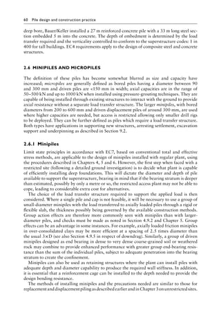
Figure 6.17 (continued)╇
(b) Charts for calculating total volume of rock enclosed by groups of anchors
arranged on rectangular grid pattern.](https://image.slidesharecdn.com/piledesignandconstructionpracticesixtheditionpdfdrive-240129074148-da7d723b/85/Pile-Design-and-Construction-Practice-Sixth-Edition-PDFDrive-pdf-349-320.jpg)

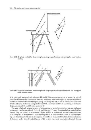
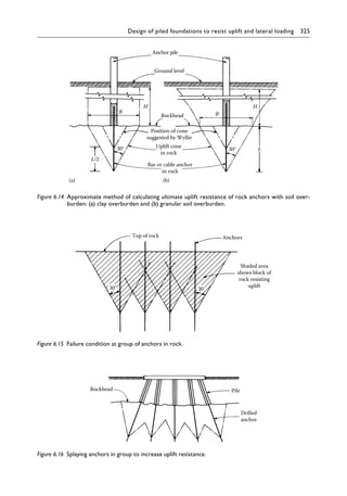
![362 Pile design and construction practice
Which is satisfactory for typical Class C25/30 grout with a design tensile strength of fctk
0.05/γC (Section 7.10.1), say, 1.2 N/mm2.
Check the uplift resistance of the overlapping rock cones:
The bond length should be increased by approximately L/2 to comply with Figure 6.12b.
Take a bond length over the cone of, say, 10 m below the surface of the weathered chalk and
space the piles at 4 m centres. Then in Figure 6.17a, Vc = 0.35 × 103 = 350 m3. Since m/L =
0.61, m = 10 × 0.61 = 6.1 m. In Figure 6.17b, S = 4 m, so that S/m = 4/7 = 0.66, and thus
ΔVm/Vc = 0. M = 2, N = 1 and P = 0, and therefore ΔVn/Vc = 0.
Rock volume anchored by pair of anchors = 350[(2 × 1)−(1 × 0.40)] = 560â•›m3.
Weight of rock resisting uplift = Gstbk = 560 × 0.5 × 9.81 = 2747 kN.
With γG stab = 0.9 as in Table 6.1, then design value of weight of rock Gstbd = 0.9 × 2747 =
2472 kN which is less than the 2800 kN uplift on the pair of piles.
Therefore, the frictional resistance on the sloping surfaces of the overlapping cones can
be taken into account. As a rough approximation, assume that the two cones act as a rect-
angular block having a volume of 560 m3, say, 10 × 8 × 7.0 m deep, and take the angle of
shearing resistance of the chalk as 30° and take K0 as 1.5:
Average unit frictional resistance on the vertical surfaces of the block
= 1.5 × tan 30° × 9.81 × 0.5 × 3.5 = 14.9 kN/m2
Characteristic frictional resistance to uplift = Rsk = (2 (10 + 8) × 7.0 × 14.9)/1.4 = 2682 kN
With the UPL partial factor on shearing resistance γϕ′ = 1.25 as in Table 6.2,
Rd = =
2682
1 25
2146 kN
.
With γQ dst = 1.5 for the variable action as in Table 6.1, design value Vdstd = 1.5 × 2 × 1400 =
4200 kN for the pair of piles. The vertical component of uplift
Vdstd = 4200 × sin 71.5 = 3983 kN
Hence, for the inequality Vdstd ≤ Gstbd + Rd as Equation 6.3a
3983 (2472 + 2146) = 4618 kN and satisfactory
If shear connectors are to be provided, the BS EN ISO 19902 procedure can be used to
calculate the required bond length. It is not strictly valid for the geometry of the connection
but this example will illustrate the use of the equations. Assume an unconfined compression
strength fcu of 25 N/mm2 at 3 days and a modular ratio of 18. For a shear key upstand height
of 10 mm and a spacing of 150 mm, the ratio h/s = 0.067.
From Equation 6.8a, stiffness factor
K =
+ +
− −
1
18
568
200
168
16
600
16
1 1
= 0.04 which is greater than the limit of 0.02
From Equation 6.8b, scale factor
Cp =
−
+
168
1000
168
500
2
2
= 1.68 which is greater than the limit of 1.5](https://image.slidesharecdn.com/piledesignandconstructionpracticesixtheditionpdfdrive-240129074148-da7d723b/85/Pile-Design-and-Construction-Practice-Sixth-Edition-PDFDrive-pdf-384-320.jpg)
![Design of piled foundations to resist uplift and lateral loading 363
From Equation 6.7a, fg sliding with the limiting values Cp = 1.5 and K = 0.02
= 1.5[2 + 140 (0.067)0.8]0.020.6 × 250.3 = 6.77 N/mm2
From Equation 6.7b, fg shear
= [0.75 − 1.4(0.067)]5 = 3.28 N/mm2
Therefore, for Equation 6.6, fg = 3.28 N/mm2 is the lower and k = 1.0, and the design
interface transfer strength
. .
.
fd =
×
=
3 28 1
1 64N/mm2
0
2
Required bond length over anchor =
×
× ×
1400 1000
168 3 1 64
π . .
= 1614 mm (using the characteristic uplift action)
Therefore, provide 1614/150 = 10.8, say, 11 shear keys spaced at 150 mm centre over a
distance of 1.6 m over anchor tube and pile.
As seen by the prescribed limits, the above equations are more applicable to large-�
diameter
piles and jacket sleeves with a grouted annulus of 50–100 mm.
Checking the application of EC2-1 Table 3.1 concrete bond values for a C20/25 grout,
fck = 20 N/mm2 and fctk 0.05 = 1.5 (note fck cube is used for BS EN ISO 19902, i.e. 25 N/mm2
for a C20/25 grout), fctd = 1.5/1.5 = 1.0 N/mm2 as Clause 3.1.6 and fbd = 2.25 × 1.0 × 1.0 =
2.25 N/mm2 as EC2-1-1 Clause 8.4.2, assuming that the shear connectors provide bond
conditions as good as the referenced ribbed bars:
Requiredbondlengthoveranchor =
×
× ×
2036 1000
168 3 2 25
π . .
= 1710 mm (using the factored load and bond stress)
The same 11 shear keys can be placed over 1.7 m to bond the anchor tube to the pile.
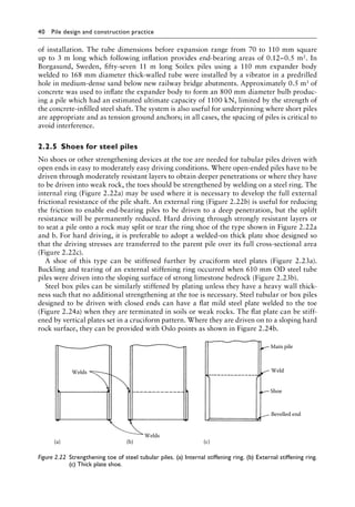
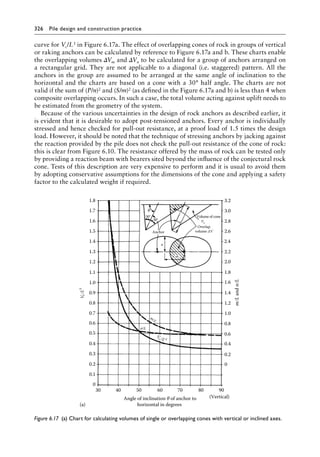
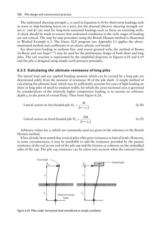
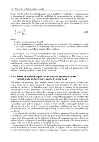
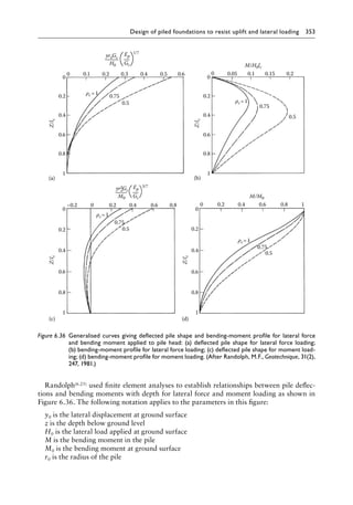
Example 6.3
A vertical bored and cast-in-place pile 900 mm in diameter is installed to a depth of 6 m in
a stiff over-consolidated clay (cu = 120 kN/m2, c′ = 10 kN/m2, ϕ′ = 25°). Find the maximum
permanent horizontal load which can be applied at a point 4 m above ground level. Also
find the maximum applied load if the lateral deflection of the pile at ground level is limited
to not more than 25 mm.
Consider first the ultimate horizontal load. For conditions of immediate application, that
is using the undrained shearing strength, from Table 6.4 for cu = 120 kN/m2, the soil modu-
lus k is 7.5 MN/m2. If the elastic modulus of concrete is 26 × 103 MN/m2 and the moment of
inertia of the pile is 0.0491 × (900)4 mm4, from Equation 6.11, the stiffness factor is
R =
× × ×
×
=
26 10 0 0490 0 9
7 5 0 9
3 3
3 4
4
. .
. .
. m](https://image.slidesharecdn.com/piledesignandconstructionpracticesixtheditionpdfdrive-240129074148-da7d723b/85/Pile-Design-and-Construction-Practice-Sixth-Edition-PDFDrive-pdf-385-320.jpg)
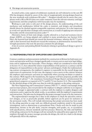
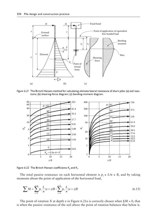
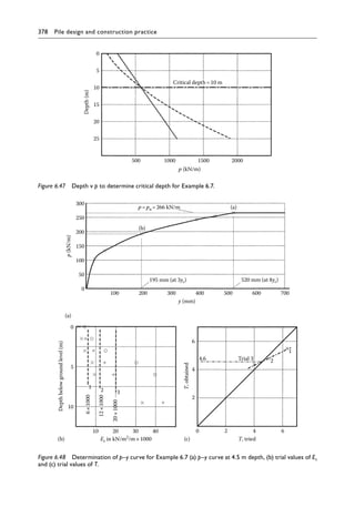
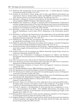
![364 Pile design and construction practice
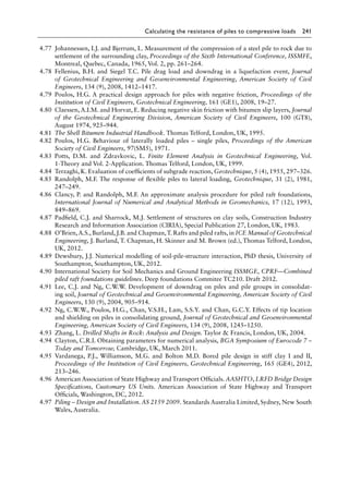
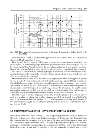
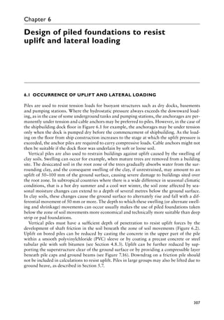
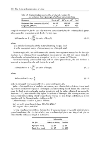
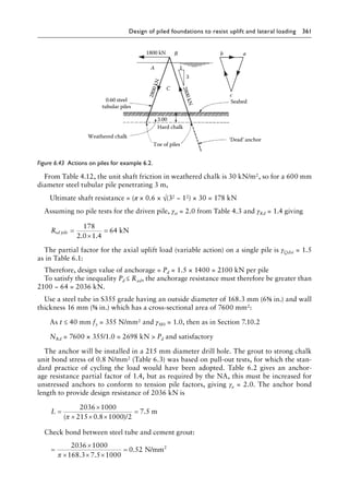
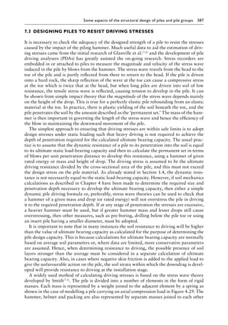
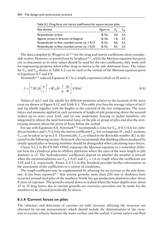
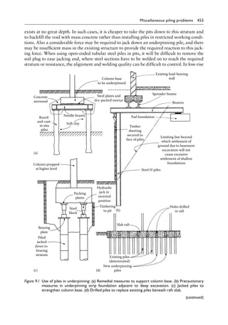
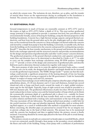
L is 6 m which is less than 2R; therefore, the pile will behave as a short rigid unit,
and the Brinch Hansen method can be used. The Brinch Hansen coefficients, as shown in
Figure 6.22 with c = cu = 120 kN/m2 and ϕ = 0, are tabulated as follows:
z (m) 0 1 2 3 4 5 6
z/B 0 1.1 2.2 3.3 4.4 5.5 6.6
Kc 2.2 5.5 6.2 6.7 7.0 7.2 7.3
cuKc 264 660 744 804 840 864 876
The soil resistance of each element 1 m wide by 1 m deep is plotted in Figure 6.44a. As a
trial, assume the point of rotation X is at 4.0 m below ground level. Then, taking moments
about point of application of Hu,
M = × × + × × + × × + × ×
− ×
∑ ( . ) ( . ) ( . ) ( . )
[(
462 1 4 5 702 1 5 5 774 1 6 5 822 1 7 5
852 1×
× + × × = +
8 5 870 1 9 5 1629
. ) ( . )] kNm per metre width of pile
If the point of rotation is raised to 3.9 m below ground level, M = +
∑ 297kNm, which
is sufficiently close to zero for the purpose of this example.
Taking moments about the centre of rotation,
Hu × = × + × + × + × ×
+
7 9 462 3 4 702 2 4 774 1 4 820 2 0 9 0 45
838
. ( . ) ( . ) ( . ) ( . . . )
( .
. . . ) ( . ) ( . )
2 0 1 0 05 852 0 6 870 1 6
× × + × + ×
Thus, Hu = 828 kN per metre width. For a pile 0.9 m wide, Hu = 0.9 × 828 = 745 kN.
Hu
(b)
0.900 pile
Depth
in
m
X
1
2
3
4
5
6
0
1094
1011
928
842
755
666
577
496
416
324
244
151
58
Ground
level
Hu
(a)
0.900 pile
Depth
in
m
0
1
2
X
3
4
5
6
264
462
660
702
744
774
804
822
840
852
864
870
876
4.00
4.00
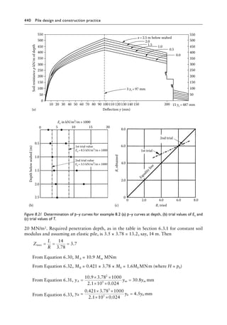
Figure 6.44╇
Variation of Brinch Hansen coefficients with depth for Example 6.3 (a) undrained and (b) drained
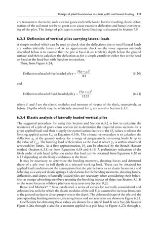
conditions.](https://image.slidesharecdn.com/piledesignandconstructionpracticesixtheditionpdfdrive-240129074148-da7d723b/85/Pile-Design-and-Construction-Practice-Sixth-Edition-PDFDrive-pdf-386-320.jpg)
![Design of piled foundations to resist uplift and lateral loading 365
Now consider the long-term stability under sustained loading, when the drained shearing
strength parameters c′ = 10 kN/m2 and ϕ′ = 25 apply. From Figure 6.22, the Brinch Hansen
coefficients for Kc and Kq are tabulated as follows:
z (m) 0 1 2 3 4 5 6
z/B 0 1.1 2.2 3.3 4.4 5.5 6.6
Kc 5.8 16 20 23 26 27 28
c′Kc 58 160 200 230 260 270 280
Kq 3.3 5.0 5.5 5.9 6.3 6.7 6.9
p0 (kN/m2) 0 18.6 39.3 58.8 78.5 98.2 118
p0Kq (kN/m2) 0 93 216 347 495 658 814
c′Kc + p0Kq (kN/m2) 58 253 416 577 755 928 1094
The soil resistance of each element 1 m deep for a pile 1 m wide is plotted in Figure 6.44b.
As a trial, consider the point of rotation X to be 4.0 m below ground level. Taking moments
about the point of application of Hu,
M = × × + × × + × × + × ×
− ×
∑ ( . ) ( . ) ( . ) ( . )
[(
155 1 4 5 335 1 5 5 496 1 6 5 666 1 7 5
842 1×
× + × × = −
8 5 1011 1 9 5 6002
. )] ( . ) kNm
If the centre of rotation is lowered to 4.5 m, then
M = + × × − × × +
= −
∑ 10 759 798 0 5 8 25 885 0 5 8 75 9604
14 051 13 4
, ( . . ) ( . . ) )]
, , 7
76 575
+ kN
which is sufficiently close to zero for the purpose of this example. Then taking moments
about the centre of rotation,
Hu × = × + × + × + ×
+ × ×
8 5 155 4 0 335 3 0 496 2 0 660 1 0
798 0 5 0
. ( . ) ( . ) ( . ) ( . )
( . .2
25 885 0 3 0 25 1011 1 1
) ( . . ) ( )
+ × × + × ×
Thus, Hu = 530 kN per metre width. Therefore, the lowest value of the ultimate load
results from drained shearing strength conditions. For a 900 mm pile, the ultimate horizon-
tal load = 0.9 × 530 = 477 kN.
Calculating the allowable horizontal load which limits the lateral deflection at ground
level to 25 mm, from Equation 6.50,
Depth to point of fixity = 1.4R = 1.4 × 3.3 = 4.62 m
From Equation 6.20 with e = 0, H = 3 × 0.025 × 837.38 × 103/4.623 = 637 kN
Therefore, the allowable load is governed by the resistance of the pile to overturning.
A factor of safety of 1.5 on the ultimate load of 477 kN will be appropriate giving an allow-
able load of 318 kN.](https://image.slidesharecdn.com/piledesignandconstructionpracticesixtheditionpdfdrive-240129074148-da7d723b/85/Pile-Design-and-Construction-Practice-Sixth-Edition-PDFDrive-pdf-387-320.jpg)
![Design of piled foundations to resist uplift and lateral loading 367
Steel grade to BS EN 10025 is S275 with fyk = 275 MN/m2, modulus of section = 2950 cm3 and
γM0 = 1.0. Hence, design bending resistance Md = 2950 × 0.0275/1.0 = 81 MNcm = 810 kNm.
From Equation 6.51, depth to point of fixity = 1.8 × 189 = 340 cm.
From Equation 6.19, ultimate horizontal load = Hu = 2 × 81 × 103/340 = 476 kN.
Global factor of safety on applied load = 476/240 = 2.0, which is satisfactory if the pile
head deflections and the pile group behaviour are within acceptable limits applying EC7
procedures.
Design action and resistances for lateral loads are determined using the partial factors
from Tables 4.1 and 4.2 (EC7 Clause 2.4.7.3.1) with γG = 1.35 and M1 factors as unity for
set A1. For SLS calculation, the partial factor is unity.
The deflections, bending moments and soil-resistance values for the single pile at the
working load can be calculated from the curves in Figure 6.28.
From Equation 6.27:
Deflection
,
cm
y F F F
F y y
=
× ×
× ×
× = =
240 1 0 189
21 10 58 064
1 329 13 29
3
3
.
. . y
y mm
From Equation 6.28:
Bending moment MF = 240 × 1.35 × 189 × Fm = 61,236Fm kNcm = 612.4Fm kNm
From Equation 6.29:
Soil reaction PF = 240 × 1.35 Fp/189 = 1.71Fp kN per cm depth = 171Fp kN per m depth.
Zmax = L/T = 9.0/1.89 = 4.8
Tabulated values of yF, MF and PF using the above partial action factor are as follows:
x (m) 0 0.5 1.0 1.5 2.0 2.5 3.0 4.0 5.0
z = x/T 0 0.27 0.53 0.80 1.06 1.33 1.60 2.13 2.66
Fy +0.92 +0.90 +0.82 +0.71 +0.61 +0.50 +0.37 +0.18 +0.04
yF (mm) +12.2 +12.0 +10.9 +9.4 +8.1 +6.6 +4.9 +2.4 —
Fm −0.91 −0.65 −0.40 −0.18 −0.03 +0.10 +0.19 +0.25 +0.21
MF (kNm) −557 −398 −245 −110 −18 +61 +116 +153 +129
Fp 0 +0.25 +0.45 +0.57 +0.62 +0.62 +0.57 +0.38 +0.13
PF (kN/m) 0 +42.7 +76.9 +97.5 +106.0 +106.0 +97.5 +65.0 +22.2
From the above table, the pile head deflection is satisfactory and the inequality Md
MF for bending of the pile is satisfied (design resistance of the pile 810 kNm maximum
bending moment of 557 kNm).
Because the piles are spaced at 125/46.7 = 2.67 diameters, the group will act as a single
unit equivalent to a block foundation having a width of 5 × 1.25 m = 6.25 m and a depth
below the ground surface of 9 m. The ultimate passive resistance to the horizontal thrust
from a block foundation can be determined from the limit state Equation C.2 in Annex C
of EC7 (parameters as given):
σp = Kp [γ z + q] + 2c √ Kp
With the 9 m depth of block and c and q = 0, passive resistance at the base of the block:
σp = 3.69 [1.3 × 9.81 × 9] = 423.5 kN/m2/m
Total resistance = 0.5 × 9 × 423.6 × 6.25 = 11,912 kN for the width of the block](https://image.slidesharecdn.com/piledesignandconstructionpracticesixtheditionpdfdrive-240129074148-da7d723b/85/Pile-Design-and-Construction-Practice-Sixth-Edition-PDFDrive-pdf-389-320.jpg)


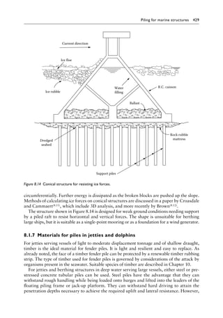


This document provides an overview of pile design and construction practices. It discusses various types of piles, including driven displacement piles (timber, precast concrete, steel), driven and cast-in-place piles (withdrawable tube, shell types), replacement piles (bored, continuous flight auger, drilled tubular), and composite piles. The document also covers piling equipment, installation methods, calculating pile resistance to compressive loads, and designing pile groups for compressive loading and lateral/uplift loading. It serves as a reference for practicing geotechnical engineers, piling contractors, and students.


