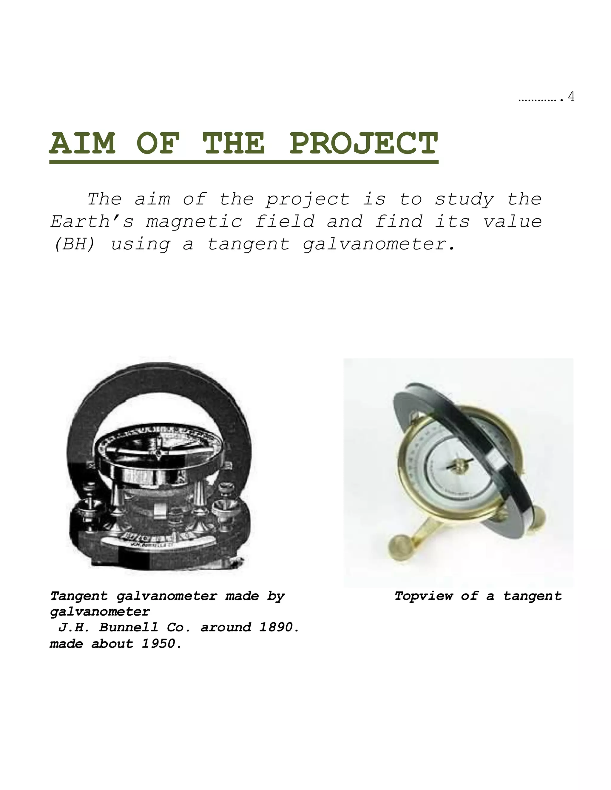
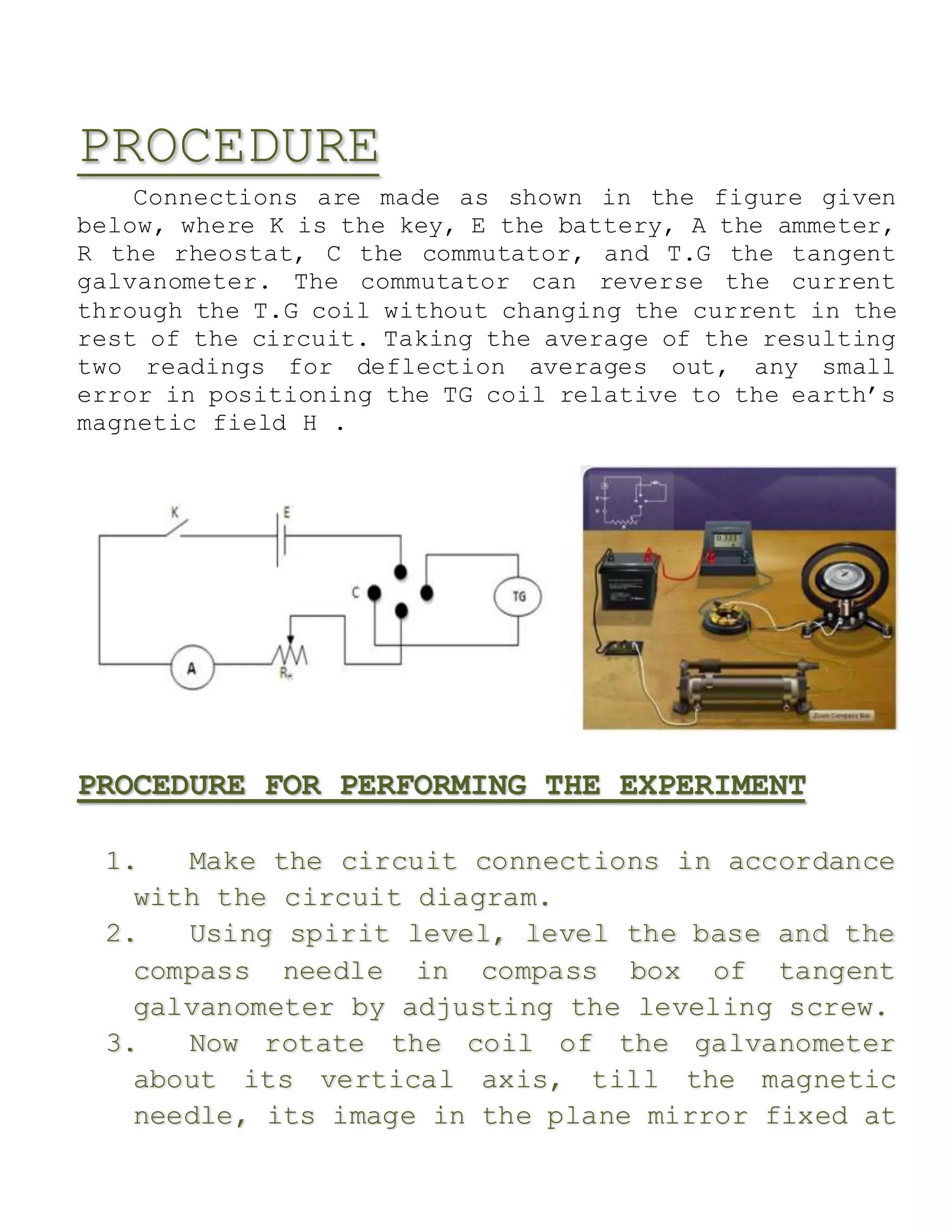
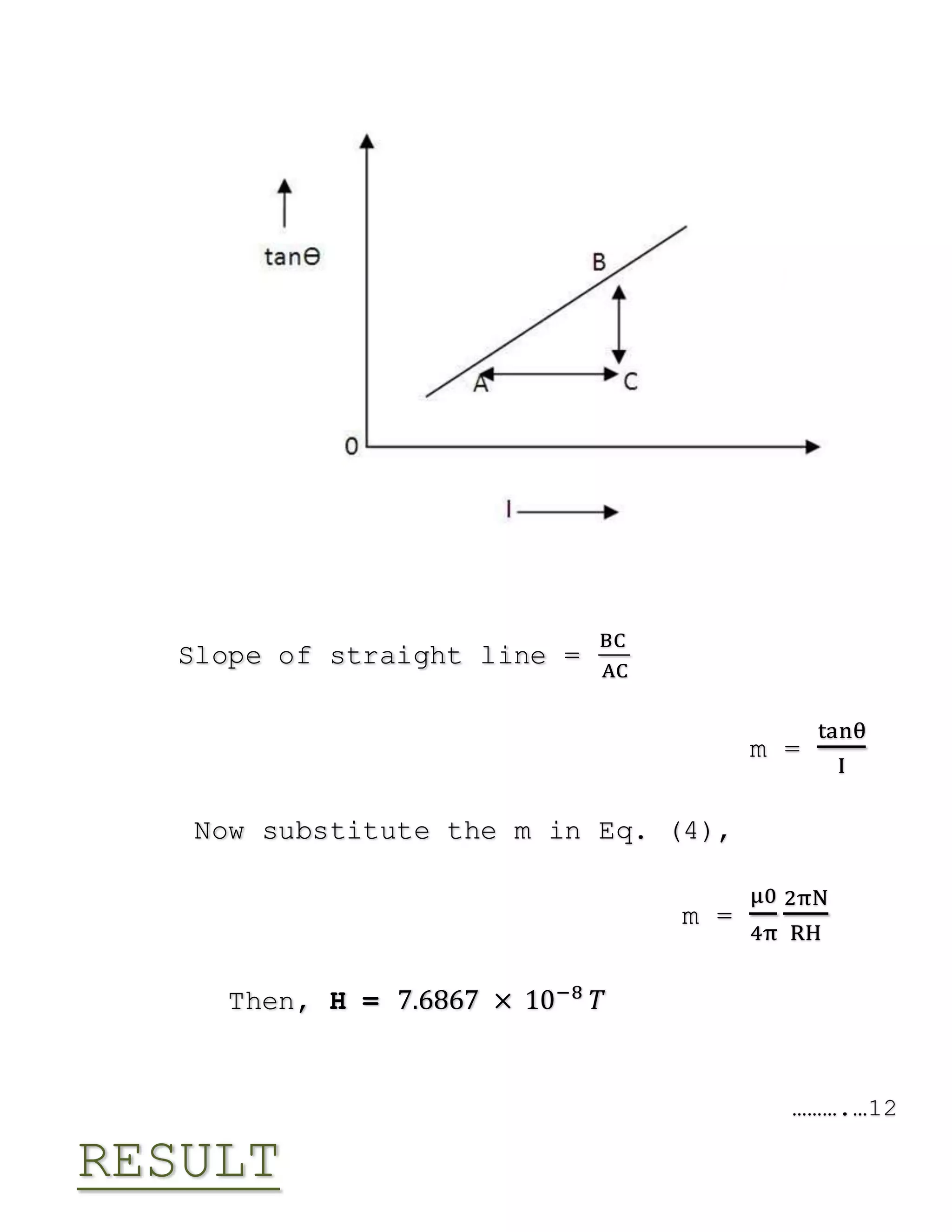
InvestigatoryProject
Physics
Royal Gondwana
Public School &
Junior College
Rushikesh Shendare
Class
XII
TABLE OF CONTENTS
Acknowledgment…………………………………………………………………………………………………………
……..3
Overview..............................................
......................................................
......................... 4
Aim of the
Project...............................................
......................................................
.... 5
Apparatus and Materials
required..............................................
....................... 6
Theory
......................................................
......................................................
..................... 7
Procedure.............................................
......................................................
....................... 9
Observations and
Graph…................................................
........................................ 11
To determine the horizontal component of
earth’s magnet
Field (H)
......................................................
......................................................
......11
From
graph.................................................
......................................................
.. 12
Result
......................................................
......................................................
..................... 13
Precautions…………………………………………………………………………………………………………………
……....13
Sources of
error……………………………………………………………………………………………………………….13
Facts.................................................
......................................................
..............................14
Applications
….....................................................
......................................................
.......14
Bibliography..........................................
......................................................
......................15
……….…..2
ACKNOWLEDGEMENT
“I would like to express my
sincere gratitude to my Physics
teacher, Mrs. Nitin
Jassal for giving us the wonderful
opportunity to do a case study and
providing vital support, guidance
and encouragement throughout the
project. Without her motivation
and help, the successful
completion of this project would
not be possible. Secondly i would
also like to thank my friends who
helped me a lot in finalizing this
project within the limited time
frame.”
……………3
OVERVIEW
The tangent galvanometer was first
described in an 1837 by Claude-Servais-
Mathias Pouillet, who later employed this
sensitive form of galvanometer to verify
Ohm’s law. To use the galvanometer, it is
first set up on a level surface and the
coil aligned with the magnetic north-south
direction. This means that the compass
needle at the middle of the coil is
parallel with the plane of the coil when it
carries no current. The current to be
measured is now sent through the coil, and
produces a magnetic field, perpendicular to
the plane of the coil and is directly
proportional to the current.
The magnitude of the magnetic
field produced by the coil is B; the
magnitude of the horizontal component the
Earth’s magnetic field is B’.The compass
needle aligns itself along the vector sum
of B and B’ after rotating through an angle
Ø from its original orientation. The vector
diagram shows that tan Ø = B/B’. Since the
magnetic field of the Earth is constant,
and B depends directly on the current, the
current is thus proportional to the tangent
of the angle through which the needle has
turned.
………….4
AIM OF THE PROJECT
The aim of the project is to study the
Earth’s magnetic field and find its value
(BH) using a tangent galvanometer.
Tangent galvanometer made by Topview of a tangent
galvanometer
J.H. Bunnell Co. around 1890.
made about 1950.
……………..5
APPARATUS AND MATERIALS
REQUIRED
 Tangent Galvanometer (TG),
 Commutator (C),
 Rheostat (R),
 Battery (E),
 Ammeter (A),
 Key (K), etc
……………6
THEORY
Tangent galvanometer is an early measuring
instrument for small electric currents. It
consists of a coil of insulated copper wire wound
on a circular non-magnetic frame. Its working is
based on the principle of the tangent law of
magnetism. When a current is passed through the
circular coil, a magnetic field (B) is produced
at the center of the coil in a direction
perpendicular to the plane of the coil.
The working of tangent galvanometer is
based on the tangent law. It is stated as when a
magnet is suspended freely in magnetic field F and
H, the magnet comes to rest making an angle θ with
the direction H such that,
F = H tan θ
(1)
When a bar magnet is suspended in two Magnetic fields B and Bh,
it comes to rest making an angle θ with the direction of Bh.
…………..7
Let a current I be passed through the coil of
radius R, having turns N. Then magnetic field
produced at the centre of coil is,
𝐹 =
μ0
4π
2πIN
𝑅
(2)
Let H is the horizontal component of earth’s
magnetic field and the magnetic needle comes to
rest at angle 𝜃 with the direction of H, then
according Eq. (1),
𝐻𝑡𝑎𝑛𝜃 =
μ0
4π
2πIN
𝑅
𝐻𝑡𝑎𝑛𝜃 = 10−7
2πIN
𝑅
𝐻 =
2π×10−7IN
𝑅𝑡𝑎𝑛𝜃
(3)
by substituting the value of current I , from eq.
(3),
𝑡𝑎𝑛𝜃
𝐼
=
𝜇0
4𝜋
2𝜋𝑁
𝑅𝐻
(4)
radius of coil of galvanometer R, deflection 𝜃 and
N, the value of H can be calculated.
………….8
PROCEDURE
Connections are made as shown in the figure given
below, where K is the key, E the battery, A the ammeter,
R the rheostat, C the commutator, and T.G the tangent
galvanometer. The commutator can reverse the current
through the T.G coil without changing the current in the
rest of the circuit. Taking the average of the resulting
two readings for deflection averages out, any small
error in positioning the TG coil relative to the earth’s
magnetic field H .
PROCEDURE FOR PERFORMING THE EXPERIMENT
1. Make the circuit connections in accordance
with the circuit diagram.
2. Using spirit level, level the base and the
compass needle in compass box of tangent
galvanometer by adjusting the leveling screw.
3. Now rotate the coil of the galvanometer
about its vertical axis, till the magnetic
needle, its image in the plane mirror fixed at
the base of the compass box and the coil, i.e.
all
4. these three lie in the same vertical plane.
In this setting,
…………..9
5. the ends of the aluminium pointer should
read zero-zero. If this is not so, rotate the
box without disturbing the position of the coil
till at least one of the ends of the pointer
stands at the zero marks.
6. By closing the key K, the current flow in
the galvanometer. Read the both ends of the
pointer. Now reverse the direction of current
by using the reversing key. When the mean
values of both deflections shown by the pointer
in the two cases (i.e. before and after
reversing the current) differ by more than 1o,
then turn slightly the vertical coil until the
two values agree. This will set the plane of
the coil exactly in the magnetic meridian.
7. By adjusting the rheostat, bring the
deflection in galvanometer around 45o. The
deflection should not be outside the range
(30o-60o).
8. Record the reading of the ammeter and the
deflection of the compass needle in the box
shown by two ends of pointer on the scale.
9. Reverse the current in the coil of
galvanometer and again record the current and
deflection of needle.
10. By changing the value of current, take four
or more set of readings and plot the graph
between I and tan𝜃. The graph will be a
straight line.
11. Measure the inner and the outer diameter of
the coil with a half metre scale at least three
times. ………….10
OBSERVATIONS
1. Range of the Ammeter –
2. Least count of Ammeter –
3. Zero error in Ammeter –
4. Number of turns used (N) –
Table 1. For variation of 𝜽 with I
S.No. Value of deflection,
θ (degree)
Mean tan θ Ammeter
reading
(A)For direct
current
For
reverse
current
θ1 θ2 θ3 θ4 Obs Corrected
1.
2.
3.
4.
5.
35
49
36
50
45
35
47
36
50
45
35
60
55
65
64
35
64
58
68
65
35
53.6
46.25
58.2
53.8
0.70
1.36
1.04
1.61
1.37
0.15
0.20
0.25
0.30
0.27
0.15
0.20
0.25
0.30
0.27
Table 2. For radius of tangent
Galvanometer
S.No. Inner
diameter
d1 (cm)
Outer
diameter d2
(cm)
Mean
diameter
d
Mean
radius
(cm)
1.
2.
3.
16.0 × 10⁻²
16.16 × 10⁻²
16.06 × 10⁻²
16.40 × 10⁻²
16.08 × 10⁻²
16.10 × 10⁻²
16.20 × 10⁻²
16.12 × 10⁻²
16.08 × 10⁻²
8.10 ×
10−2
8.06 × 10⁻²
8.04 × 10⁻²
Mean radius of coil R = 8.04 × 10⁻²
……….…11
GRAPH
Slope of straight line =
BC
AC
m =
tanθ
I
Now substitute the m in Eq. (4),
m =
μ0
4π
2πN
RH
Then, H = 7.6867 × 10⁻⁸
𝑇
……….…12
RESULT
The value of earth’s magnetic field by using a
tangent galvanometer is
H = 7.6867 × 10⁻⁸
𝑇
PRECAUTIONS
1. The battery should be freshly charged.
2. The magnetic needle should swing freely in
the horizontal plane.
3. The plane of coil must be set in magnetic
meridian.
4. There should be no parallax in noting down
the readings of ammeter and deflection.
5. All the readings should be adjusted between
30o and 60o.
SOURCES OF ERROR
1. There may a magnetic material around
apparatus.
2. The plane of coil will not be exactly in
the magnetic meridian.
……….…13
FACTS
The tangent galvanometer is an early measuring
instrument for Current
 The magnetic field produced by a circular
coil carrying current I is Proportional to I
.
 The S.I unit of magnetic field is Tesla .
 The magnitude of horizontal intensity of
earth’s magnetic field is3.5x10⁻⁵ T .
 For better result while doing tangent
galvanometer experiment, the deflection
should be in between 30o
-60o
.
 The value of μ₀ is 4πx10⁻⁷ NA⁻²
APPLICATIONS
 T.G. can be used to measure the magnitude of
the horizontal component of the geomagnetic
field.
 The principle can be used to compare the
galvanometer constants.
 For calibration of secondary instruments.
……….…14
BIBLIOGRAPHY
 Tangent Galvanometer (Procedure)
:Comprehensive Physics Activities Volume I :
Laxmi Publications Pvt Ltd.
 Tangent Galvanometer (Theory) : Comprehensive
Physics Activities Volume I : Laxmi
Publications Pvt Ltd.
 Tangent Galvanometer (Precautions and
Sources of error) : Comprehensive Physics
Activities Volume I : Laxmi Publications Pvt
Ltd.
 Galvanometer:
http://physics.kenyon.edu/EarlyApparatus/Elec
trical_Measurements/Tangent_Galvanometer/Tang
ent_Galvanometer.html
 Galvanometer: Wikipedia, the free
encyclopedia
en.wikipedia.org/wiki/Galvanometer
……….…15
Physics Earth magnetic field using tangent galvanometer

Physics Earth magnetic field using tangent galvanometer

  • 1.
    InvestigatoryProject Physics Royal Gondwana Public School& Junior College Rushikesh Shendare Class XII
  • 2.
    TABLE OF CONTENTS Acknowledgment………………………………………………………………………………………………………… ……..3 Overview.............................................. ...................................................... .........................4 Aim of the Project............................................... ...................................................... .... 5 Apparatus and Materials required.............................................. ....................... 6 Theory ...................................................... ...................................................... ..................... 7 Procedure............................................. ...................................................... ....................... 9 Observations and Graph…................................................ ........................................ 11 To determine the horizontal component of earth’s magnet Field (H) ...................................................... ...................................................... ......11 From graph.................................................
  • 3.
    ...................................................... .. 12 Result ...................................................... ...................................................... ..................... 13 Precautions………………………………………………………………………………………………………………… ……....13 Sourcesof error……………………………………………………………………………………………………………….13 Facts................................................. ...................................................... ..............................14 Applications …..................................................... ...................................................... .......14 Bibliography.......................................... ...................................................... ......................15 ……….…..2 ACKNOWLEDGEMENT
  • 4.
    “I would liketo express my sincere gratitude to my Physics teacher, Mrs. Nitin Jassal for giving us the wonderful opportunity to do a case study and providing vital support, guidance and encouragement throughout the project. Without her motivation and help, the successful completion of this project would not be possible. Secondly i would also like to thank my friends who helped me a lot in finalizing this project within the limited time frame.” ……………3 OVERVIEW
  • 5.
    The tangent galvanometerwas first described in an 1837 by Claude-Servais- Mathias Pouillet, who later employed this sensitive form of galvanometer to verify Ohm’s law. To use the galvanometer, it is first set up on a level surface and the coil aligned with the magnetic north-south direction. This means that the compass needle at the middle of the coil is parallel with the plane of the coil when it carries no current. The current to be measured is now sent through the coil, and produces a magnetic field, perpendicular to the plane of the coil and is directly proportional to the current. The magnitude of the magnetic field produced by the coil is B; the magnitude of the horizontal component the Earth’s magnetic field is B’.The compass needle aligns itself along the vector sum of B and B’ after rotating through an angle Ø from its original orientation. The vector diagram shows that tan Ø = B/B’. Since the magnetic field of the Earth is constant, and B depends directly on the current, the current is thus proportional to the tangent of the angle through which the needle has turned.
  • 6.
    ………….4 AIM OF THEPROJECT The aim of the project is to study the Earth’s magnetic field and find its value (BH) using a tangent galvanometer. Tangent galvanometer made by Topview of a tangent galvanometer J.H. Bunnell Co. around 1890. made about 1950.
  • 7.
    ……………..5 APPARATUS AND MATERIALS REQUIRED Tangent Galvanometer (TG),  Commutator (C),  Rheostat (R),  Battery (E),  Ammeter (A),  Key (K), etc
  • 8.
    ……………6 THEORY Tangent galvanometer isan early measuring instrument for small electric currents. It consists of a coil of insulated copper wire wound on a circular non-magnetic frame. Its working is based on the principle of the tangent law of magnetism. When a current is passed through the circular coil, a magnetic field (B) is produced at the center of the coil in a direction perpendicular to the plane of the coil. The working of tangent galvanometer is based on the tangent law. It is stated as when a magnet is suspended freely in magnetic field F and
  • 9.
    H, the magnetcomes to rest making an angle θ with the direction H such that, F = H tan θ (1) When a bar magnet is suspended in two Magnetic fields B and Bh, it comes to rest making an angle θ with the direction of Bh. …………..7 Let a current I be passed through the coil of radius R, having turns N. Then magnetic field produced at the centre of coil is, 𝐹 = μ0 4π 2πIN 𝑅 (2)
  • 10.
    Let H isthe horizontal component of earth’s magnetic field and the magnetic needle comes to rest at angle 𝜃 with the direction of H, then according Eq. (1), 𝐻𝑡𝑎𝑛𝜃 = μ0 4π 2πIN 𝑅 𝐻𝑡𝑎𝑛𝜃 = 10−7 2πIN 𝑅 𝐻 = 2π×10−7IN 𝑅𝑡𝑎𝑛𝜃 (3) by substituting the value of current I , from eq. (3), 𝑡𝑎𝑛𝜃 𝐼 = 𝜇0 4𝜋 2𝜋𝑁 𝑅𝐻 (4) radius of coil of galvanometer R, deflection 𝜃 and N, the value of H can be calculated. ………….8
  • 11.
    PROCEDURE Connections are madeas shown in the figure given below, where K is the key, E the battery, A the ammeter, R the rheostat, C the commutator, and T.G the tangent galvanometer. The commutator can reverse the current through the T.G coil without changing the current in the rest of the circuit. Taking the average of the resulting two readings for deflection averages out, any small error in positioning the TG coil relative to the earth’s magnetic field H . PROCEDURE FOR PERFORMING THE EXPERIMENT 1. Make the circuit connections in accordance with the circuit diagram. 2. Using spirit level, level the base and the compass needle in compass box of tangent galvanometer by adjusting the leveling screw. 3. Now rotate the coil of the galvanometer about its vertical axis, till the magnetic needle, its image in the plane mirror fixed at
  • 12.
    the base ofthe compass box and the coil, i.e. all 4. these three lie in the same vertical plane. In this setting, …………..9 5. the ends of the aluminium pointer should read zero-zero. If this is not so, rotate the box without disturbing the position of the coil till at least one of the ends of the pointer stands at the zero marks. 6. By closing the key K, the current flow in the galvanometer. Read the both ends of the pointer. Now reverse the direction of current by using the reversing key. When the mean values of both deflections shown by the pointer in the two cases (i.e. before and after reversing the current) differ by more than 1o, then turn slightly the vertical coil until the two values agree. This will set the plane of the coil exactly in the magnetic meridian. 7. By adjusting the rheostat, bring the deflection in galvanometer around 45o. The deflection should not be outside the range (30o-60o).
  • 13.
    8. Record thereading of the ammeter and the deflection of the compass needle in the box shown by two ends of pointer on the scale. 9. Reverse the current in the coil of galvanometer and again record the current and deflection of needle. 10. By changing the value of current, take four or more set of readings and plot the graph between I and tan𝜃. The graph will be a straight line. 11. Measure the inner and the outer diameter of the coil with a half metre scale at least three times. ………….10 OBSERVATIONS 1. Range of the Ammeter – 2. Least count of Ammeter – 3. Zero error in Ammeter – 4. Number of turns used (N) – Table 1. For variation of 𝜽 with I S.No. Value of deflection, θ (degree) Mean tan θ Ammeter reading (A)For direct current For reverse current
  • 14.
    θ1 θ2 θ3θ4 Obs Corrected 1. 2. 3. 4. 5. 35 49 36 50 45 35 47 36 50 45 35 60 55 65 64 35 64 58 68 65 35 53.6 46.25 58.2 53.8 0.70 1.36 1.04 1.61 1.37 0.15 0.20 0.25 0.30 0.27 0.15 0.20 0.25 0.30 0.27 Table 2. For radius of tangent Galvanometer S.No. Inner diameter d1 (cm) Outer diameter d2 (cm) Mean diameter d Mean radius (cm) 1. 2. 3. 16.0 × 10⁻² 16.16 × 10⁻² 16.06 × 10⁻² 16.40 × 10⁻² 16.08 × 10⁻² 16.10 × 10⁻² 16.20 × 10⁻² 16.12 × 10⁻² 16.08 × 10⁻² 8.10 × 10⁻² 8.06 × 10⁻² 8.04 × 10⁻² Mean radius of coil R = 8.04 × 10⁻² ……….…11 GRAPH
  • 15.
    Slope of straightline = BC AC m = tanθ I Now substitute the m in Eq. (4), m = μ0 4π 2πN RH Then, H = 7.6867 × 10⁻⁸ 𝑇 ……….…12 RESULT
  • 16.
    The value ofearth’s magnetic field by using a tangent galvanometer is H = 7.6867 × 10⁻⁸ 𝑇 PRECAUTIONS 1. The battery should be freshly charged. 2. The magnetic needle should swing freely in the horizontal plane. 3. The plane of coil must be set in magnetic meridian. 4. There should be no parallax in noting down the readings of ammeter and deflection. 5. All the readings should be adjusted between 30o and 60o. SOURCES OF ERROR 1. There may a magnetic material around apparatus. 2. The plane of coil will not be exactly in the magnetic meridian.
  • 17.
    ……….…13 FACTS The tangent galvanometeris an early measuring instrument for Current  The magnetic field produced by a circular coil carrying current I is Proportional to I .  The S.I unit of magnetic field is Tesla .  The magnitude of horizontal intensity of earth’s magnetic field is3.5x10⁻⁵ T .  For better result while doing tangent galvanometer experiment, the deflection should be in between 30o -60o .  The value of μ₀ is 4πx10⁻⁷ NA⁻² APPLICATIONS  T.G. can be used to measure the magnitude of the horizontal component of the geomagnetic field.  The principle can be used to compare the galvanometer constants.
  • 18.
     For calibrationof secondary instruments. ……….…14 BIBLIOGRAPHY  Tangent Galvanometer (Procedure) :Comprehensive Physics Activities Volume I : Laxmi Publications Pvt Ltd.  Tangent Galvanometer (Theory) : Comprehensive Physics Activities Volume I : Laxmi Publications Pvt Ltd.  Tangent Galvanometer (Precautions and Sources of error) : Comprehensive Physics Activities Volume I : Laxmi Publications Pvt Ltd.  Galvanometer: http://physics.kenyon.edu/EarlyApparatus/Elec trical_Measurements/Tangent_Galvanometer/Tang ent_Galvanometer.html
  • 19.
     Galvanometer: Wikipedia,the free encyclopedia en.wikipedia.org/wiki/Galvanometer ……….…15