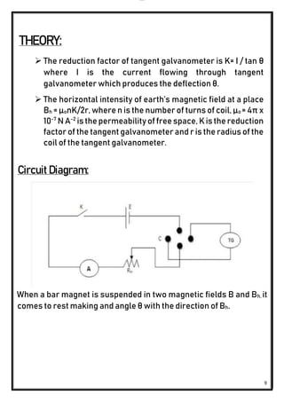
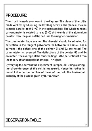
1. The document describes an experiment to measure the Earth's magnetic field using a tangent galvanometer. A circuit is constructed including a tangent galvanometer, magnet, and current source. Current is passed through the circuit and deflections of the galvanometer needle are measured.
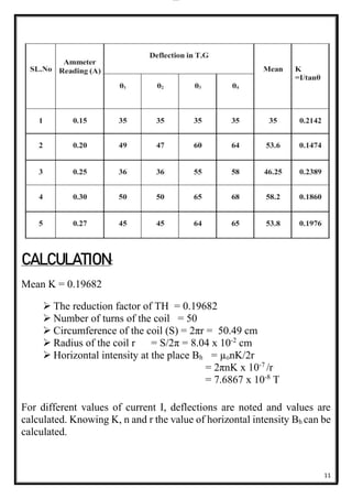
2. Calculations are done to determine the reduction factor of the tangent galvanometer and the horizontal intensity of the Earth's magnetic field at the location.
3. The results found the reduction factor to be 0.19682 A and the horizontal magnetic field intensity to be 7.6867 x 10⁻⁵ T.