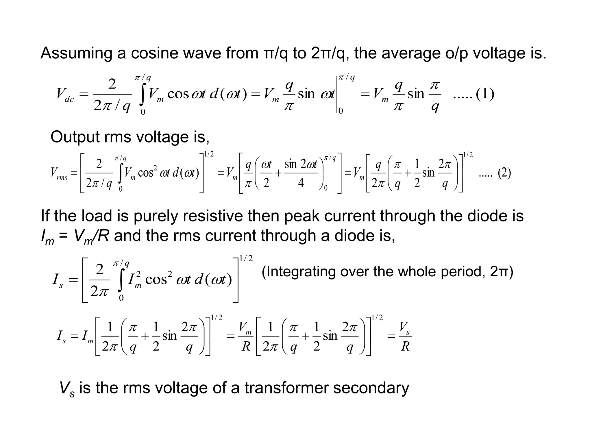
This document discusses multiphase star rectifiers and three-phase bridge rectifiers. It provides the following key points:
1) Multiphase star rectifiers use multiple phases (q phases) with each diode conducting for 2π/q periods to rectify the input. They can be considered as multiple single-phase half-wave rectifiers.
2) Three-phase bridge rectifiers provide full-wave rectification with six pulses on the output voltage from the conduction sequence of diodes. They have higher output voltage and lower ripple compared to star rectifiers.
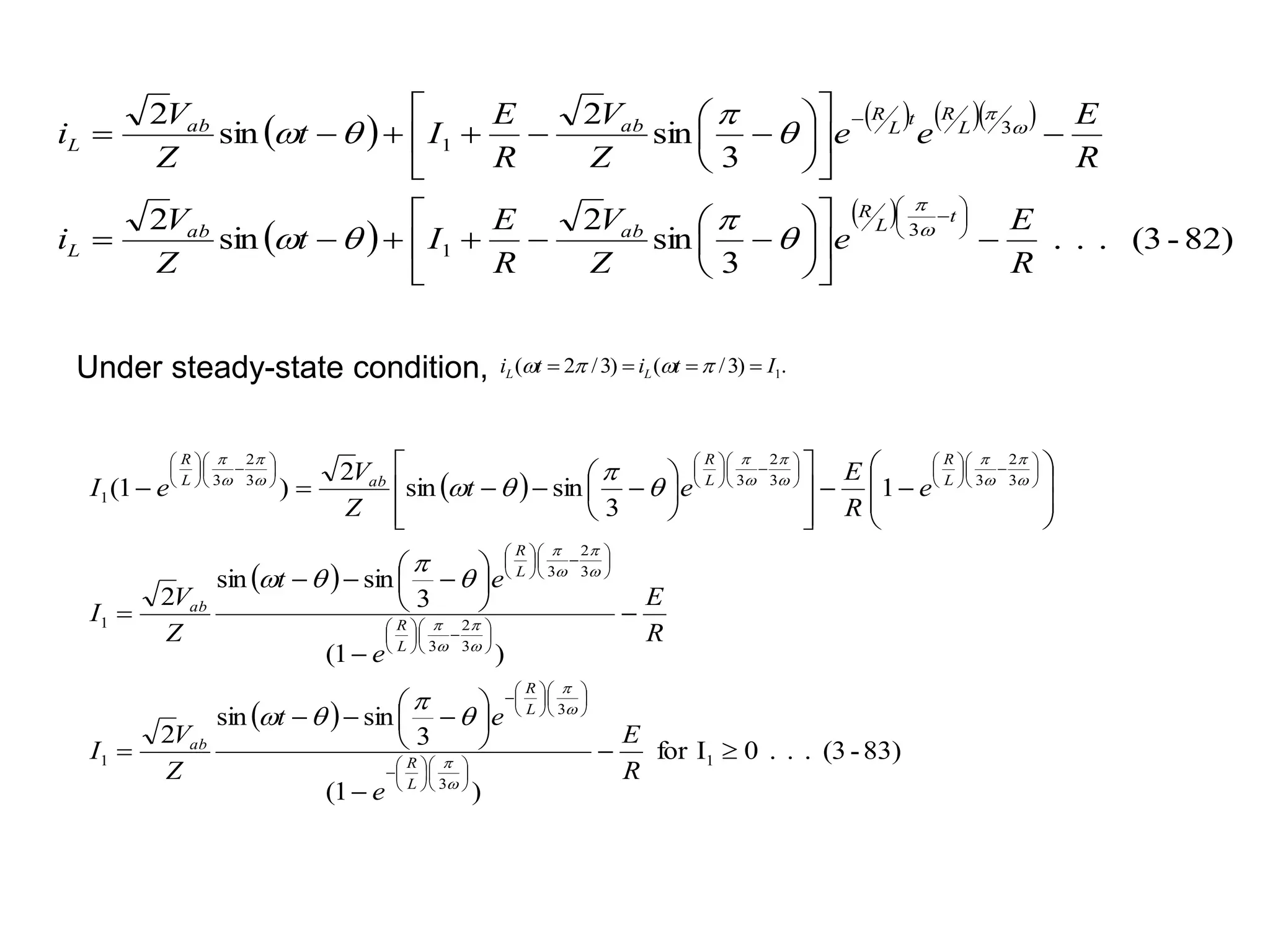
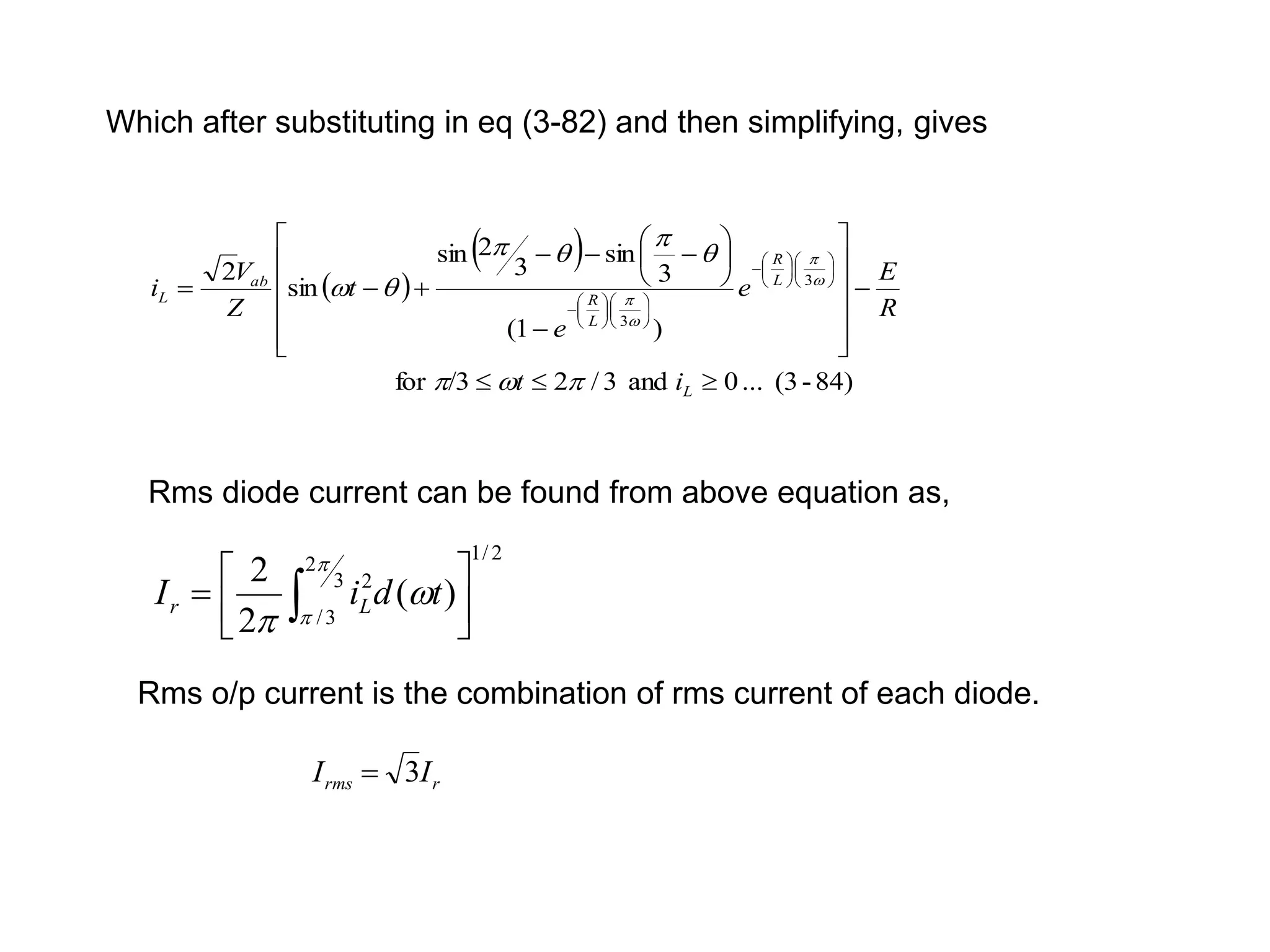
3) Equations are given for the output voltage and current characteristics of both rectifier types with resistive and RL loads.