
Recommended
Recommended
More Related Content
What's hot
What's hot (20)
Similar to Clark c500 30 55 forklift service repair manual
Similar to Clark c500 30 55 forklift service repair manual (20)
More from fjjsekfksmem
More from fjjsekfksmem (20)
Recently uploaded
Recently uploaded (20)
Clark c500 30 55 forklift service repair manual
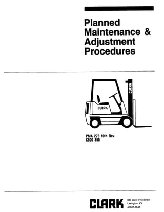
- 1. Planned Maintenance & Adjustment Procedures PMA 273 10th Rev. c500 355
- 2. INDUSTRIAL TRUCK DIVISION MARKETING TRAINING DEPT. CLARK OWNER SAFE MAINTENANCE PRACTICES Powered industrial trucks may become hazardous if adequate maintenance is not done. Therefore, maintenance facilities, pgrsonnel and procedures must be provided. Maintenance and inspection of all powered industrial trucks should be done in agreement with the recommenda- tion in this manual and the following practices. 1. A scheduled preventive maintenance, lubrication, and inspection system must be followed. 2. Only qualified and authorized personnel should be permitted to maintain, repair, adjust, and inspect industrial trucks. 3. Before Leaving The Truck: A. Stop Truck. B. Fully lower the load engaging means. C. Put directional controls in neutral. D. Apply the parking brake. E. Stop the engine or turn off power. F. Lock the control or ignition circuit. G. Put blocks at the wheels if truck is on a ramp, or being worked on. 4. Before Working On Truck: A. Raise wheels free of floor or disconnect power source. B. Use blocks or other positive truck positioning devices. C. Put blocks under the load engaging means, innennast(s), or chassis before working under them. Before working on engine fuel system of gasoline powered trucks with gravity feed fuel systems, make sure fuel shutoff valve is closed. Before working on engine fuel system of LP gas powered trucks, close LP gas cylinder valve and run engine until there is no more fuel in the system and engine stops running. Operation to check performance of the truck or attachments must be done in a clear, authorized, safe area. Before Starting To Operate The Truck: A. Be in operating position. B. Push clutch (or brake pedal on automatic transmission and electric trucks). C. Put the directional controls in neutral. D. Start engine or turn on power. E. Before operating truck, check functioning of lift and tilt systems, directional and speed controls, steering, warning devices, brakes, and any attachment. (If used) F. Release parking brake. - continued - 1023-Z REV SEP 83 (FRONT)
- 3. INDUSTRIAL TRUCK DIVISION CMRKMARKETING TRAINING DEPT OWNER SAFE MAINTENANCE PRACTICES (CONT.) 6. Avoid fire hazards and have fire protection equipment available. Do not use an open flame to check level, or for leakage, of fuel, electrolyte or coolant. Do not use open pans of fuel or flammable cleaning fluids for cleaning parts. 7. Provide ventilation to the work area, vent exhaust fumes, and keep shop clean and floor dry. 8. Handle LP gas cylinders with care. Do not drop, dent, or damage in any way. 9. 10. 11. 12. Brakes, steering mechanisms, con- trol mechanisms, warning devices, lights, governors, lift overload devices, guards and safety devices must be inspected regularly and maintained in a safe operating condition. All parts of lift and tilt mechan- isms and frame members must be carefully and regularly inspected and maintained in a safe operating condition. Special trucks or devices designed and approved for hazardous area operation must receive special attention to make sure that maint- enance keeps the original, approved safe operating features. Fuel systems must be checked for leaks and condition of parts. Extra special consideration must be given in the case of a leak in the fuel system. Action must be taken to prevent the use of the truck until the leak has been corrected. 13. 14. 15. 16. 17. 18. All hydraulic systems must be regularly inspected and maintained in conformance with good practice. Tilt cylinders, valves, and other like parts must be checked to make sure that "drift" has not devel- oped to the extent that it would create a hazard. Capacity, operation and maintenance instructions plates, tags, or decals must be maintained in legible condition. Batteries, motors, controllers, limit switches, protective devices, electrical conductors and connec- tions must be inspected and maintained in conformance with good practice. Special attention must be paid to the condition of elec- trical insulation. Industrial trucks must be kept in a clean condition to minimize fire hazards and help in the detection of loose or defective parts. Modifications and additions which affect capacity and safe truck operation must not be done by the customer or user without manufacturers prior written ap- proval. Capacity, operation and maintenance instruction plates, tags or decals must be changed accordingly. Care must be taken to make sure that all replacement parts are interchangeable with the original parts and of a quality equal to that provided in the original equipment. 1023-Z REV SEP 83 (BACK)
- 4. INDUSTRIAL TRUCK DIVISION MARKETING TRAINING DEPT. SAFETY MESSAGES PLEASE READ AND UNDERSTAND THE SAFETY MESSAGES SHOWN BELOW BEFORE YOU DO ANY WORK ON A LIFT TRUCK NAMEPLATES & DECALS LIFT TRUCK MAINTENANCE DO NOT OPERATE A LIFT TRUCK WITH DAMAGED OR LOST DECALS AND NAMEPLATES. REPLACE THEM IMMEDIATELY. THEY CONTAIN IMPORTANT INFORMATION. DO NOT WORK ON THIS TRUCK UNLESS YOU ARE TRAINED AND AUTHORIZED AND KNOW THE CORRECT MAINTENANCE PROCE- DURES. PERSONAL INJURY WEAR EYE GLASSES, SAFETY SHOES AND CORRECT FITTING CLOTHING WHEN WORKING ON LIFT TRUCKS. INJURY CAN RESULT IF YOU DO NOT WEAR PROTECTION. FALLING FORKS DO NOT WALK OR STAND UNDER RAISED FORKS. THE FORKS CAN FALL AND CAUSE INJURY OR DEATH. AIR PRESSURE WEAR EYE PROTECTION & PROTEC- TIVE CLOTHING WHEN CLEANING OR DRYING WITH AIR PRESSURE. REDUCE PRESSURE TO [207 kPa] 30 PSI. DEBRIS REMOVED WITH AIR PRESSURE CAN CAUSE INJURY. HYDRAULIC FLUID PRESSURE DO NOT USE YOUR HANDS TO CHECK FOR HYDRAULIC LEAKAGE. FLUID UNDER PRESSURE CAN PENETRATE YOUR SKIN AND CAUSE SERIOUS INJURY. 1315-Z FEB 84
- 5. PM ILLUSTRATION OF MACHINE C500 35/40/45/60/55/S60 -- C500 H30/H40/H50 ~500 Y4O/Y45/Y5O/Y55/SY60 C500 HY4O/HY50 Page 1 Code: PM-273, REV JUL 82
- 6. INDUSTRIAL TRUCK DIVISION CUSTOMER SERVICES ENGINEERINGDEPARTMENT, BATTLE CREEK FOREWORD PLANNED MAINTENANCE SECTION The Planned Maintenance Frocedures located in the front of this book provide a basic step by step guide which should be followed in servicing the vehicle, Adjustment Frocedures, specifications and other data including lubrication guides, are found in the rear of this book and are listed under GROUP and Section Numbers. Refer to the Index or the Product Identification Card. About Planned Maintenance Planned Maintenance is a program in which inspections, minor adjustments, lubrication, oil changes and replacement of filters are performed on a scheduled and systematic basis. A solid PM program should incorporate a method of record keeping which enables you to better determine FM schedules and enables you to track the maintenance costs per machine. An effective PM program should incorporate two basic phases: 1. An inspection performed by the driver or maintenance man at the beginning of each shift. This is a quick visual check for obvious damage and leaks *.. a check of engine oil and water levels, lights, instruments and warning devices. 2. THE PLANNED MAINTENANCE ROUTINE IS BASED ON 50 TO 250 OPERATING HOURS . . . WITH THE INTERVAL BE I NG DETERM INED BY OPERATING CONDITIONS. Records will tel 1 you how often FM should be done. If an operation is clean and not punishing, a PM interval can be extended. If an operation is extremely dirty and punishing, the PM interval may have to be reduced. Thus o“. the PM interval can be tailored to answer the needs of your operation. If the FM is religiously followed, needs for repair, major adj us tment and component replacement will be discovered automatically and such work will be done only as needed. For instance, brake checks which are part of the FM wi I1 uncover the need for adjustments and/or repairs which may be required periodically, Who can say? The point is that this will be done only when needed and that’s true for all systems and components, Thus, in this program we are able to eliminate 500, 1000 and 2000 hour inspections and the things normally covered in these inspections will be done only when the PM uncovers the need for repairs. The objectives of PM are: 1, To reduce costly unscheduled downtime, 2, Reduce maintenance costs. 3. Increase vehicle productivity. 4. Above all, to increase personal safety of drivers and other personnel. Inspection Forms To insure that the daily inspection and PM are properly performed, we recommend the use of the inspection forms in GROUP 40. Such forms not only provide a guide for the inspections and procedures, but serve as a record in tracking maintenance requirements for each vehicle. Moreover, they will assist you in determining when to schedule a vehicle for major repairs which can be done without the disruptive effect of unscheduled downtime. Inspection Forms may be purchased from your local CLARK Dealer. SPECIAL NOTICE TO ALL USERS OF THIS MANUAL. IF .e. in the process of using this manual for PM procedures, adjustments, references, etc . . . you find that this manual can be improved in any way, put your ideas in writing and send them to: CUSTOMER SERVICES ENGINEERING CLARK EQU I PMENT COMPANY BATTLE CREEK, MICHIGAN (49016) We can’t promise that your idea wi 11 be used, but it will be seriously considered. If you do submit any such ideas, please understand that Clark Equipment Company can use it without obligation. Page 2 Code: PM-273, REV JUL 77
- 7. cl!mw PM 1. Alternator Maintenance ............ GROUP 12, Section 1 2. Axle End Lubrication . . . . . . . . . . . . . . GROUP 20, Section 1 3. Bearings (Steer Wheel)............. GROUP 26, Section 3 4. Brake Adjusters (Service) . . . . . . . . . GROUP 23, Section 3 5. Brake Bleeding .................... GROUP 23, Section 1 6. Brake Pedal Adjustment ............ GROUP 23, Section 2 7. Clutch Adjustment ................. GROUP 04, Section 1 8. Cooling System Maintenance . . . . . . . . GROUP 01, Section 2 9. Fuel Pump Tests ................... GROUP 02, Section 2 10. Governor Adjustment ............... GROUP 02, Section 1 11. Hydraulic System Pressure Check . . . GROUP 30, Section 1 12. Lift Chains ....................... GROUP 34, Section 2 13. Lubrication Charts . . . . . . . . . . . . . . . . GROUP 01, Section 1 14. Lubrication Key ............. . . . . . . GROUP 40, Section 4 14. 15. 16. 17. 18. 19. 20. 21. 22. 23. 24. 25. 26. Driver Restraint System Checks ... GROUP 39, Section 1 Name Plates & Machine Stampings ... GROUP 40, Section 1 Parking Brake Adjustment .......... GROUP 23, Section 4 PM Inspection & Drivers Daily Inspection Forms .................. GROUP 40, Section 3 Specifications .................... GROUP 40, Section 2 Steering Adjustments .............. GROUP 26, Section 2 Steering Gear Adjustment .......... GROUP 25, Section 1 Steering Pressure Check ........... GROUP 26, Section 1 Transmission Fluid Aeration GROUP 06, Section 2 Transmission Fluid Cooling . . . . . . . . GROUP 06, Section 3 Transmission Pressure Checks ...... GROUP 06, Section 1 Upright Adjustment ................ GROUP 34, Section 1 Wheels & Tires .................... GROUP 22, Section 1 Code: PMA-273, REV MAY 84 Page 3
- 8. INDUSTRIAL TRUCK DIVISION SERVICE ENGINEERING DEPARTMENT, BATTLE CREEK ABOUT PM A special coding system on the PM check sheet allows the PM man to efficiently report truck condition, with a minimum number of words. AS the PM is performed, a check is made on the check sheet indicating truck condition regarding a potential problem, or needs urgent repair. Whenever a system or component is faulty or un- safe, it must be noted on the PM check sheet, and reported to the designated authority at the conclusion of the PM. What should a PM include? The best answer is to go through a PM based on the knowledge and ex- perience of PM men, service managers, engineers and customer services engineering personnel o P.M. OBJECTIVES? To reduce costly unscheduled downt i me, reduce maintenance costs, increase truck productivity, and . . . above all . . . to increase personal safety of drivers and other personne 1 . These worthwhile ends can be met only through sensible, consistent measures which include . . . 1. Complete inspection to uncover minor or potential trouble before it becomes major. 2. Air cleaning and lubricating the machine to reduce dirt damage and excessive wear. 3. Making adjustments to assure proper and safe functioning of systems and components. Fig. 12618 What should a P. M. include? 0C-r 73 Page 4 Fig. 10889 Code: PM -273
- 9. INDUSTRIAL TRUCK DIVISION SERVICE ENGINEERING DEPARTMENT, BATTLE CREEK Make a quick visual check of the truck. Look for signs of obvious and heavy leaks. Check mounting and condition of the driver’s overhead guard. Check the condition of the load back rest. Fig. 12141 Fig. 12142 Fig. 12143 Code : PMA-273 OCT 73 Page 5
- 10. INDUSTRIAL TRI JCK DIVISION SERVICE ENGINEERING DEPArRTMENT, BATTLE CREEK Check for excessive leakage at the lift cylinder. Check for damaged chains. Check chain adjustment by making sure the chains are under equal tension . . . and by . . . Fig. 12144 Fig. 12145 OCT 73 Page 6 Fig. 12146 Code : PMA-273
- 11. INDUSTRIAL TRUCK DIVISION SERVICE ENGINEERING DEPARTMENT, BATTLE CREEK . . . checking wear patterns in the rai Is. A wear pattern like this indicates that chain adjustment is about right. But . . . . . . a wear pattern like this means that the chains are too long and must be adjusted to correct length. Check the forks to make sure they are not bent or broken. Fig. 12147 Fig. 12148 Code: PMA-273 OCT 73 Fig. 12149 Page 7
- 12. INDUSTRIAL TRUCK DIVISION CUSTOMERSERVICESGROUP Check the fork latches to make sure they work properly. Standard Uprights: Deck Numbers beqinninq with an “F”. Check the Fabreeka (Stop) Pads for damage, and check to make sure the pads contact the rail tie bar at the same time when lowering inner slide. Reference: Fig. 10910. With innerslide fully lowered, both stop blocks must contact rail tie bar. Full Free Lift Uprights: Deck Numbers beqinninq with an “Ml’. Check the Fabreeka (Stop) Pads for damage, and see if there is some clearance between bottom of pad/s and tie bar. Pads must not contact tie bar. Reference: Fig. 10911 o Check to make sure inner rails are not lower than outer rails. Fig. 12150 PADS MUST-CONTACT OUTER RAIL T1E BAR INNER RAtL / Fig, 10910 I FABREEKA PADS MUST NOT Fig. 10911 Page 8 Code: PM-273, REV MAY 76
- 13. Check tires for excessive wear and cuts and pry out of tire treads any objects which could dam- age the tires. Also check wheel lug nuts for tightness and make sure none are missing. Fig. 12151 Now . . . check the brake pedal for free play and the brake pedal pad for excessive wear. Next . . . check the neutral starting switch by Fig. 12152
- 14. INDUSTRIAL TRl SERVICE ENGINEERING DEPP JCK DIVISION hRTMENT, BATTLE CREEK . . . check the neutral starting switch after the floorboard is removed. At that time, make sure the wires are spread as shown. If the engine still starts in gear, the switch must be adjus- ted or replaced. Next . . . check inching. To do this . . . start the engine, engage the transmission, accelerate, and depress the brake pedal until the transmis- sion disengages. While sti 11 accelerating, release the pedal slowly. The truck should inch smoothly as the pedal is released. Also check the pedal for sponginess and to make sure it doesn’t hit the floorboard. Now . . . check the power steering. To do this, drive slowly forward and cramp the hand wheel full right and left . . . to reduce tire wind-up and to neutralize the power steering booster valve. Fig. 12154 Fig. 12155 OCT 73 Page IO Fig. 12156 Code : PM4-273
- 15. Thank you very much for your reading. Please Click Here. Then Get COMPLETE MANUAL. NO WAITING NOTE: If there is no response to click on the link above, please download the PDF document first and then click on it.
- 16. INDUSTRIAL TRUCK DIVISION SERVICE ENGINEERING DEPARTMENT, BATTLE CREEK Then . . . check drive tire inside turning diam- eters which should be about equal in forward left and right turns. While driving, listen for unusual drive train noise. Next . . . Fig. 11459 . . . cramp the hand wheel very hard to left and right . . . with engine idling and truck not mov- ing. The engine should not lug down. If it does, power steering adjustment is indicated. Fig. 12158 Now . . . check for upright free play and racking by tilting the upright fore and aft with the forks fully raised. If there is excessive free play between rails and channels, upright adjust- ment is required. If there is racking, adjust- ment of cylinder rod yokes is required. Fig. 12159 Code: PMA-273 OCT 73 Page 11
- 17. INDUSTRIAL TRUCK DIVISION SERVICE ENGINEERING DEPARTMENT, BATTLE CREEK i!ext . . . check instruments, horn, head and tail 1ights, indicator lights, and warning 1ights. Nod . . . r*move the side hoods . . . . . . remove the floor board and . . . Fig. 12160 Fig. 12161
- 18. INDUSTRIAL TRUCK DIVISION CUSTOMER SERVICES EN6lNEERlN6 DEPARTMENT, BATTLE CREEK Expose the engine compartment by lifting the seat and swinging the battery out. q! WARNING------- DO NOT WELD IN THE VICINITY OF THE FUEL TANK TO AVOID AN EXPLOSION AND PERSONAL INJURY. Fig. 12163 Use a two-foot extension on the air hose and clean the radiator from the counterweight side. q! WARNING------- DO NOT USE AIR PRESSURE GREATER THAN 30 PSI. WEAR GOGGLES WHEN CLEANING WITH AIR PRESSURE TO PROTECT YOUR EYES. Fig. 12164 Clean the radiator from the engine side. Clean the engine. Fig. 12165 Code: PM-273, REV MAY 81 Page 13