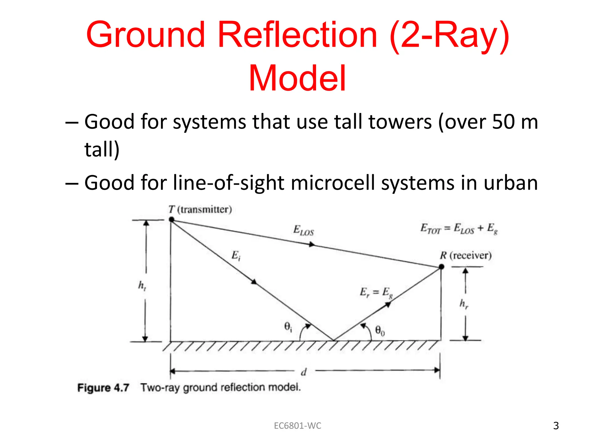
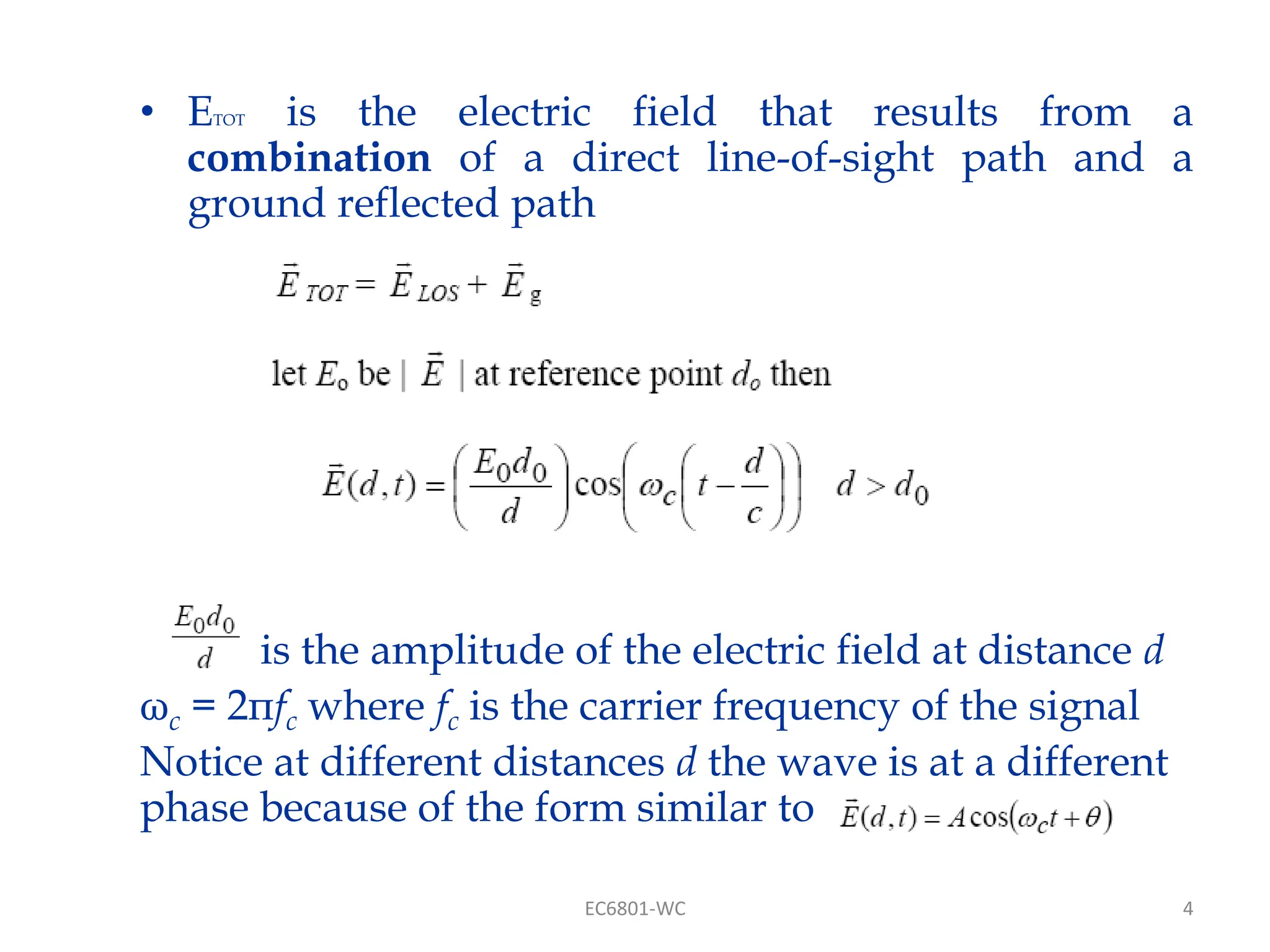
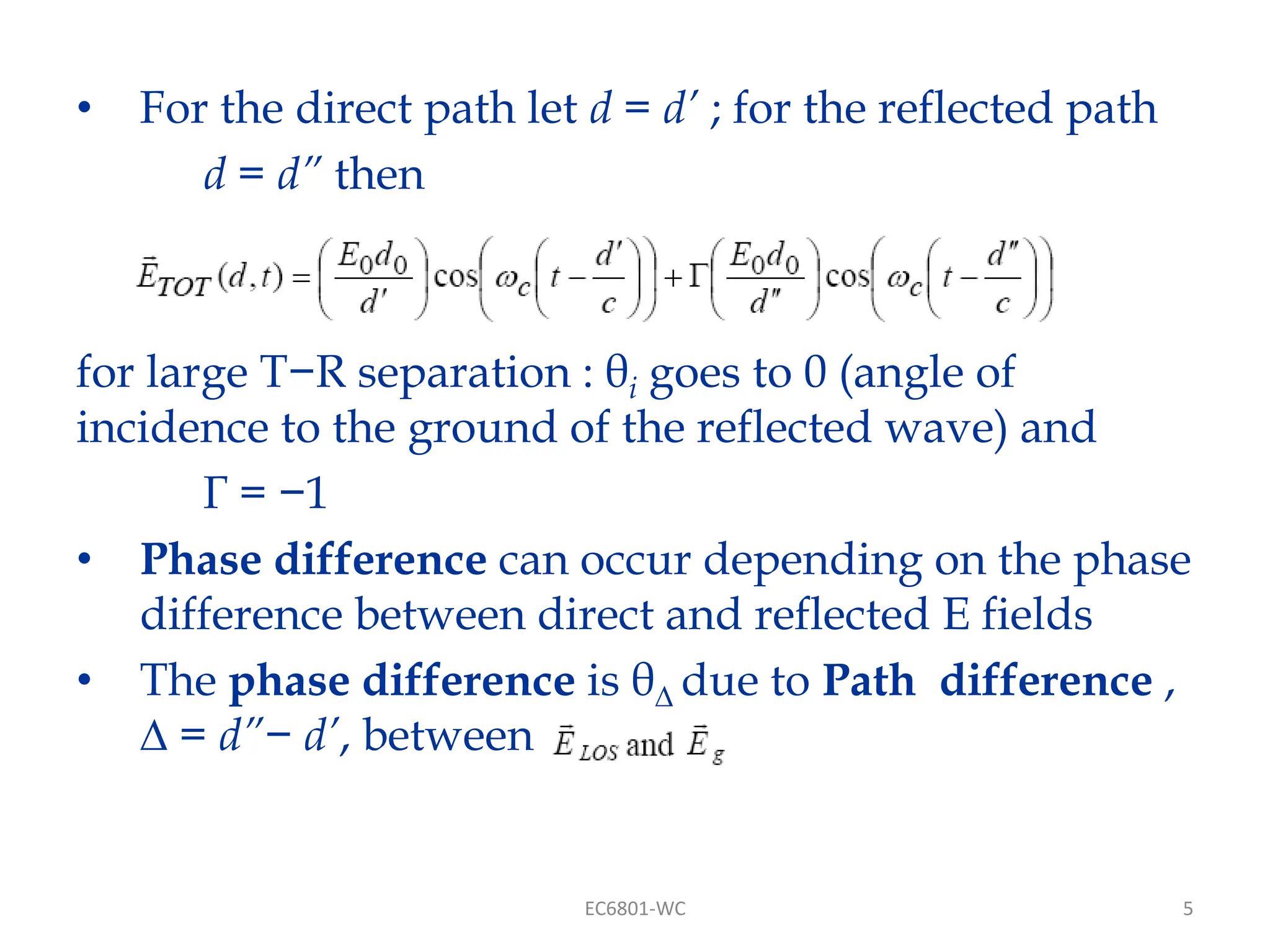
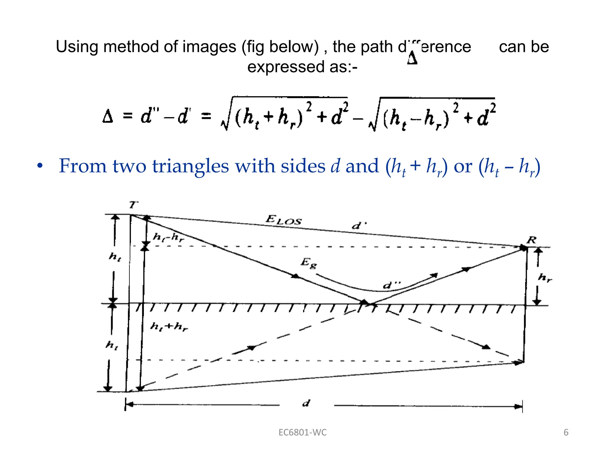
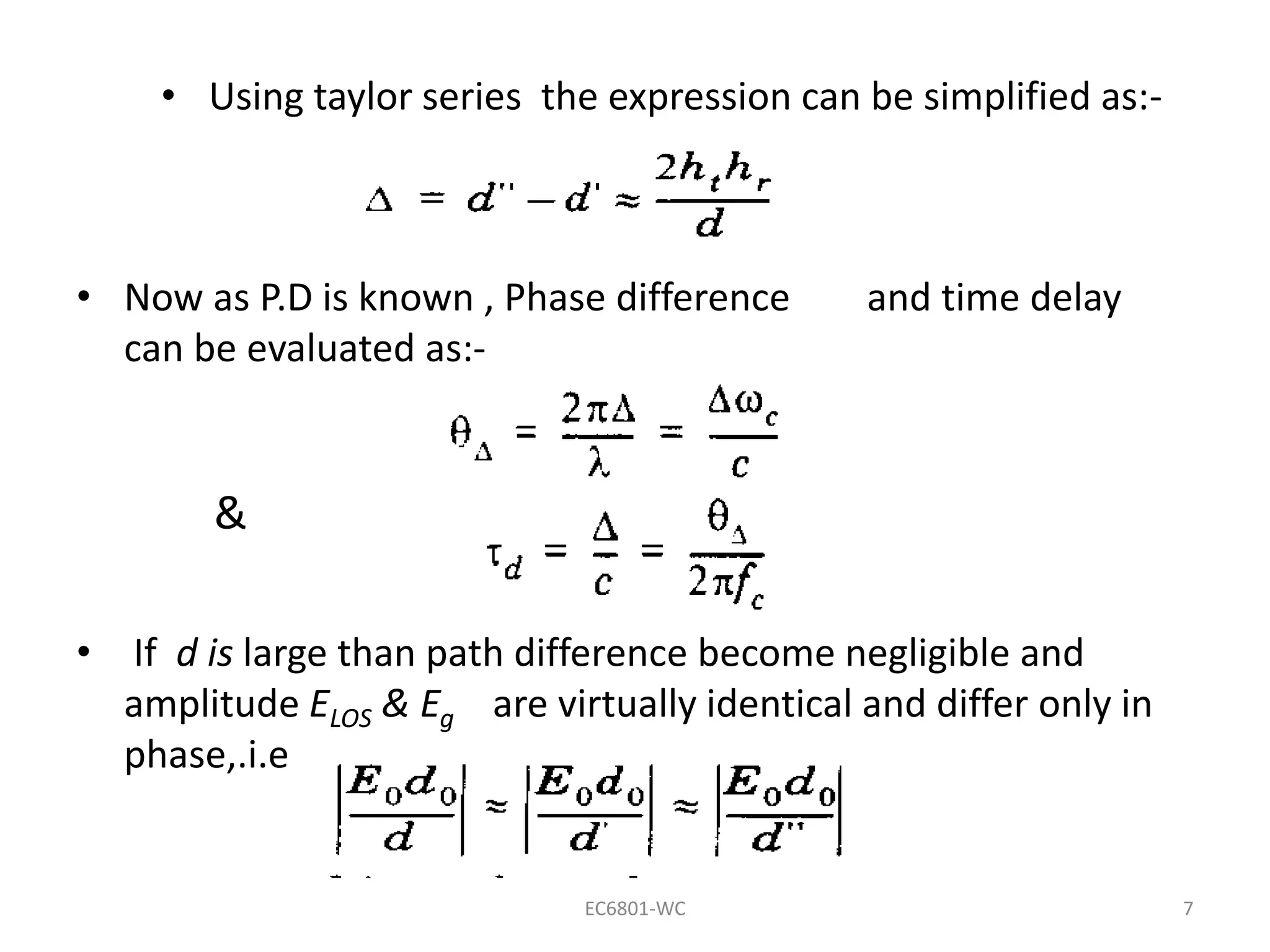
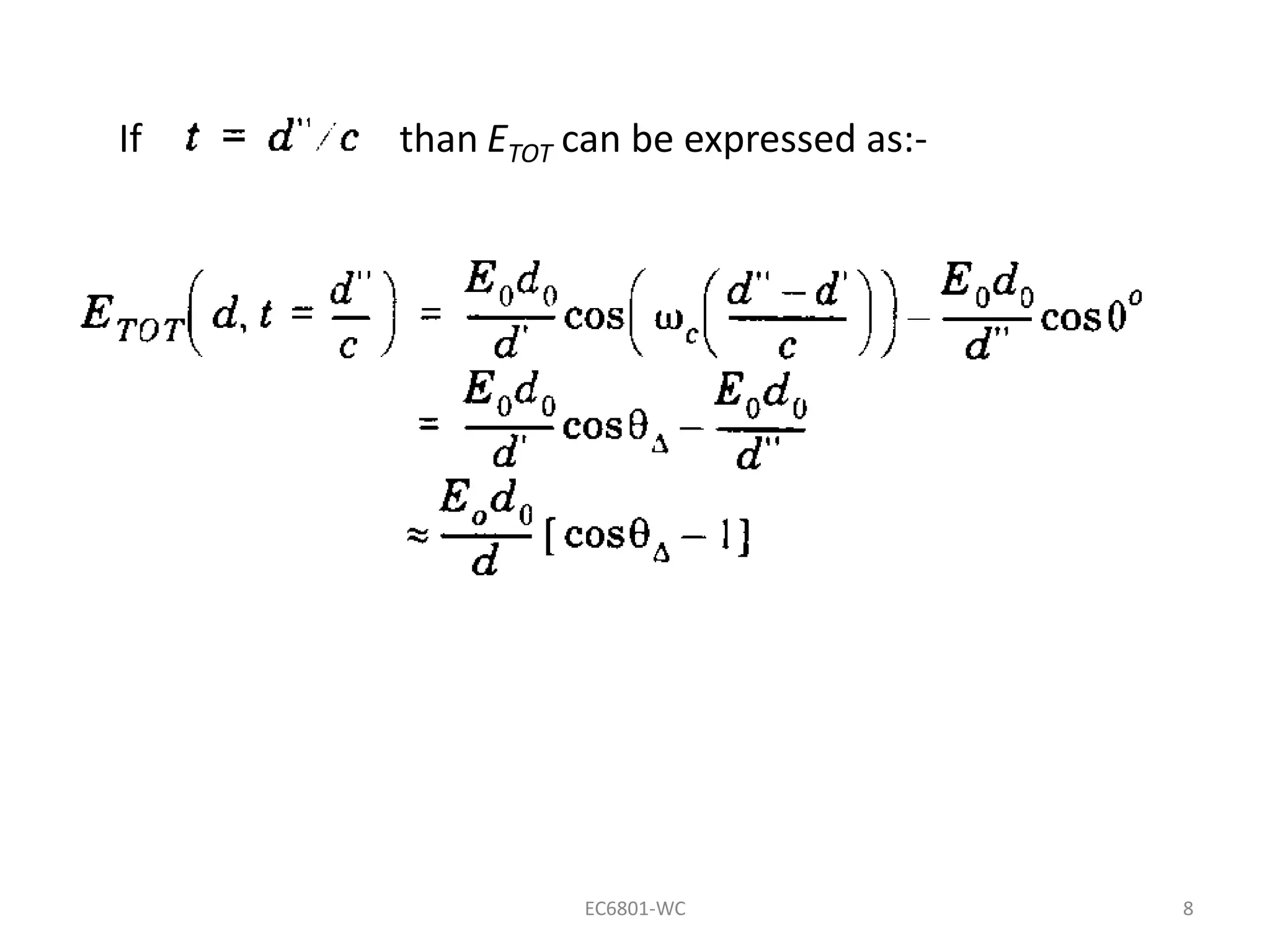
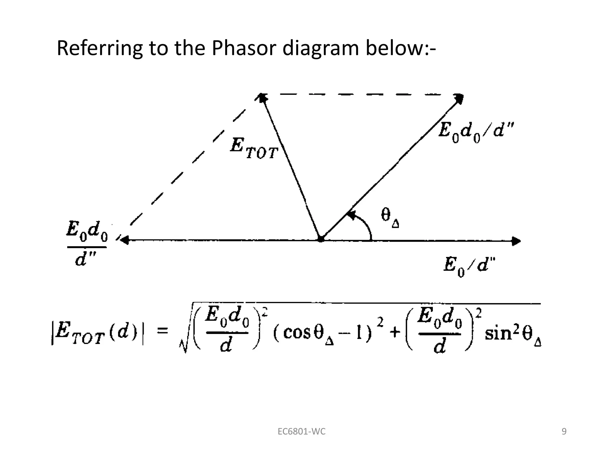
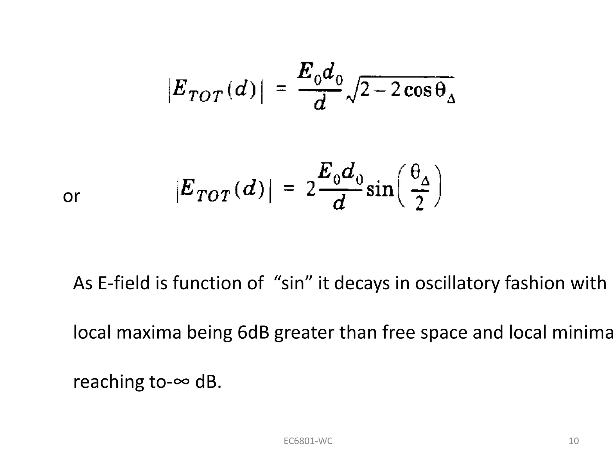
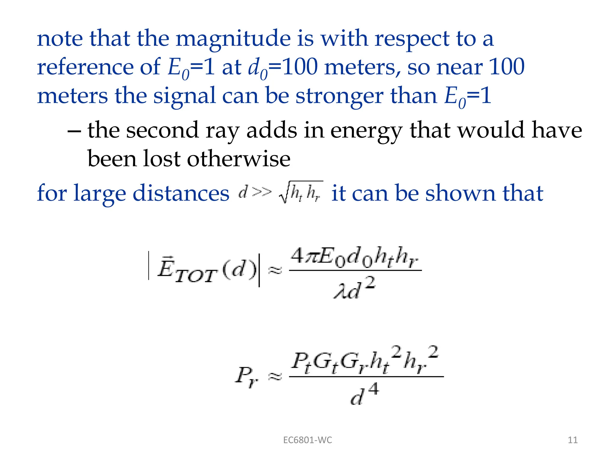
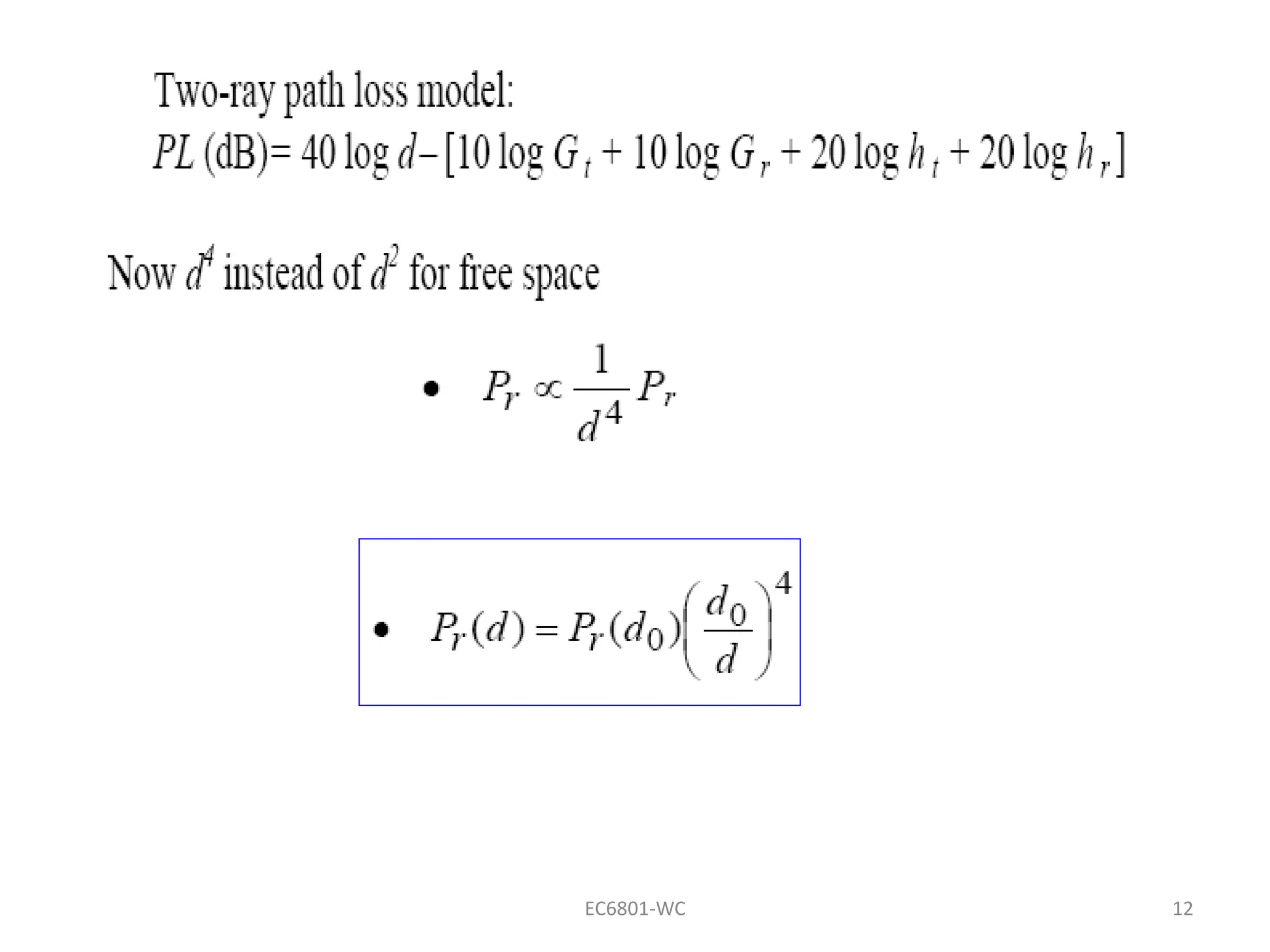
PATH LOSS MODELS
Presented by
Dr.S.Mary Praveena
Associate Professor
ECE Department
Sri Ramakrishna Institute of Technology
Coimbatore
EC6801-WC 1
The Three Basic Propagation Mechanisms
• Basic propagation mechanisms
– reflection
– diffraction
– scattering
• Reflection occurs when a propagating electromagnetic
wave impinges upon an object which has very large
dimensions when compared to the wavelength, e.g.,
buildings, walls.
• Diffraction occurs when the radio path between the
transmitter and receiver is obstructed by a surface that
has sharp edges.
• Scattering occurs when the medium through which the
wave travels consists of objects with dimensions that are
small compared to the wavelength.
EC6801-WC 2
3
Ground Reflection (2-Ray)
Model
– Good for systems that use tall towers (over 50 m
tall)
– Good for line-of-sight microcell systems in urban
environments
EC6801-WC
4
• ETOT is the electric field that results from a
combination of a direct line-of-sight path and a
ground reflected path
is the amplitude of the electric field at distance d
ωc = 2πfc where fc is the carrier frequency of the signal
Notice at different distances d the wave is at a different
phase because of the form similar to
EC6801-WC
5
• For the direct path let d = d’ ; for the reflected path
d = d” then
for large T−R separation : θi goes to 0 (angle of
incidence to the ground of the reflected wave) and
Γ = −1
• Phase difference can occur depending on the phase
difference between direct and reflected E fields
• The phase difference is θ∆ due to Path difference ,
∆ = d”− d’, between
EC6801-WC
6
Using method of images (fig below) , the path difference can be
expressed as:-
• From two triangles with sides d and (ht + hr) or (ht – hr)
EC6801-WC
EC6801-WC 7
• Using taylor series the expression can be simplified as:-
• Now as P.D is known , Phase difference and time delay
can be evaluated as:-
• If d is large than path difference become negligible and
amplitude ELOS & Eg are virtually identical and differ only in
phase,.i.e
&
EC6801-WC 8
If than ETOT can be expressed as:-
EC6801-WC 9
Referring to the Phasor diagram below:-
EC6801-WC 10
or
As E-field is function of “sin” it decays in oscillatory fashion with
local maxima being 6dB greater than free space and local minima
reaching to-∞ dB.
11
note that the magnitude is with respect to a
reference of E0=1 at d0=100 meters, so near 100
meters the signal can be stronger than E0=1
– the second ray adds in energy that would have
been lost otherwise
for large distances it can be shown that
EC6801-WC
12
EC6801-WC

Path Loss model for wireless communication

  • 1.
    PATH LOSS MODELS Presentedby Dr.S.Mary Praveena Associate Professor ECE Department Sri Ramakrishna Institute of Technology Coimbatore EC6801-WC 1
  • 2.
    The Three BasicPropagation Mechanisms • Basic propagation mechanisms – reflection – diffraction – scattering • Reflection occurs when a propagating electromagnetic wave impinges upon an object which has very large dimensions when compared to the wavelength, e.g., buildings, walls. • Diffraction occurs when the radio path between the transmitter and receiver is obstructed by a surface that has sharp edges. • Scattering occurs when the medium through which the wave travels consists of objects with dimensions that are small compared to the wavelength. EC6801-WC 2
  • 3.
    3 Ground Reflection (2-Ray) Model –Good for systems that use tall towers (over 50 m tall) – Good for line-of-sight microcell systems in urban environments EC6801-WC
  • 4.
    4 • ETOT isthe electric field that results from a combination of a direct line-of-sight path and a ground reflected path is the amplitude of the electric field at distance d ωc = 2πfc where fc is the carrier frequency of the signal Notice at different distances d the wave is at a different phase because of the form similar to EC6801-WC
  • 5.
    5 • For thedirect path let d = d’ ; for the reflected path d = d” then for large T−R separation : θi goes to 0 (angle of incidence to the ground of the reflected wave) and Γ = −1 • Phase difference can occur depending on the phase difference between direct and reflected E fields • The phase difference is θ∆ due to Path difference , ∆ = d”− d’, between EC6801-WC
  • 6.
    6 Using method ofimages (fig below) , the path difference can be expressed as:- • From two triangles with sides d and (ht + hr) or (ht – hr) EC6801-WC
  • 7.
    EC6801-WC 7 • Usingtaylor series the expression can be simplified as:- • Now as P.D is known , Phase difference and time delay can be evaluated as:- • If d is large than path difference become negligible and amplitude ELOS & Eg are virtually identical and differ only in phase,.i.e &
  • 8.
    EC6801-WC 8 If thanETOT can be expressed as:-
  • 9.
    EC6801-WC 9 Referring tothe Phasor diagram below:-
  • 10.
    EC6801-WC 10 or As E-fieldis function of “sin” it decays in oscillatory fashion with local maxima being 6dB greater than free space and local minima reaching to-∞ dB.
  • 11.
    11 note that themagnitude is with respect to a reference of E0=1 at d0=100 meters, so near 100 meters the signal can be stronger than E0=1 – the second ray adds in energy that would have been lost otherwise for large distances it can be shown that EC6801-WC
  • 12.