Download to read offline


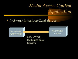


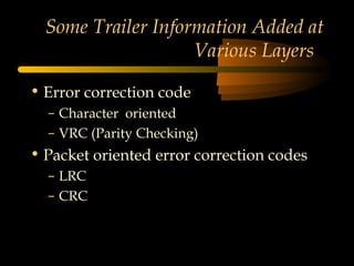


The document discusses the ISO-OSI 7-layer reference model and related IEEE standards. It covers the purpose and functions of each layer, including the physical, data link, network, transport, session, presentation and application layers. It also describes how data is formatted and encapsulated as it passes through each layer. Finally, it discusses the IEEE 802 standards group and some of the key standards they developed that apply to networking, particularly at the data link and physical layers.


