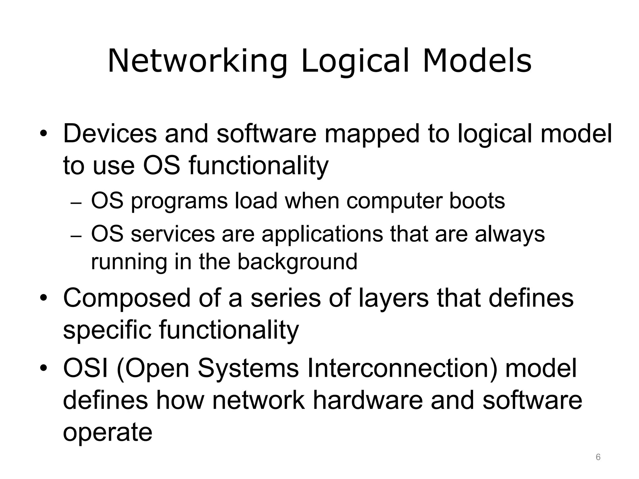
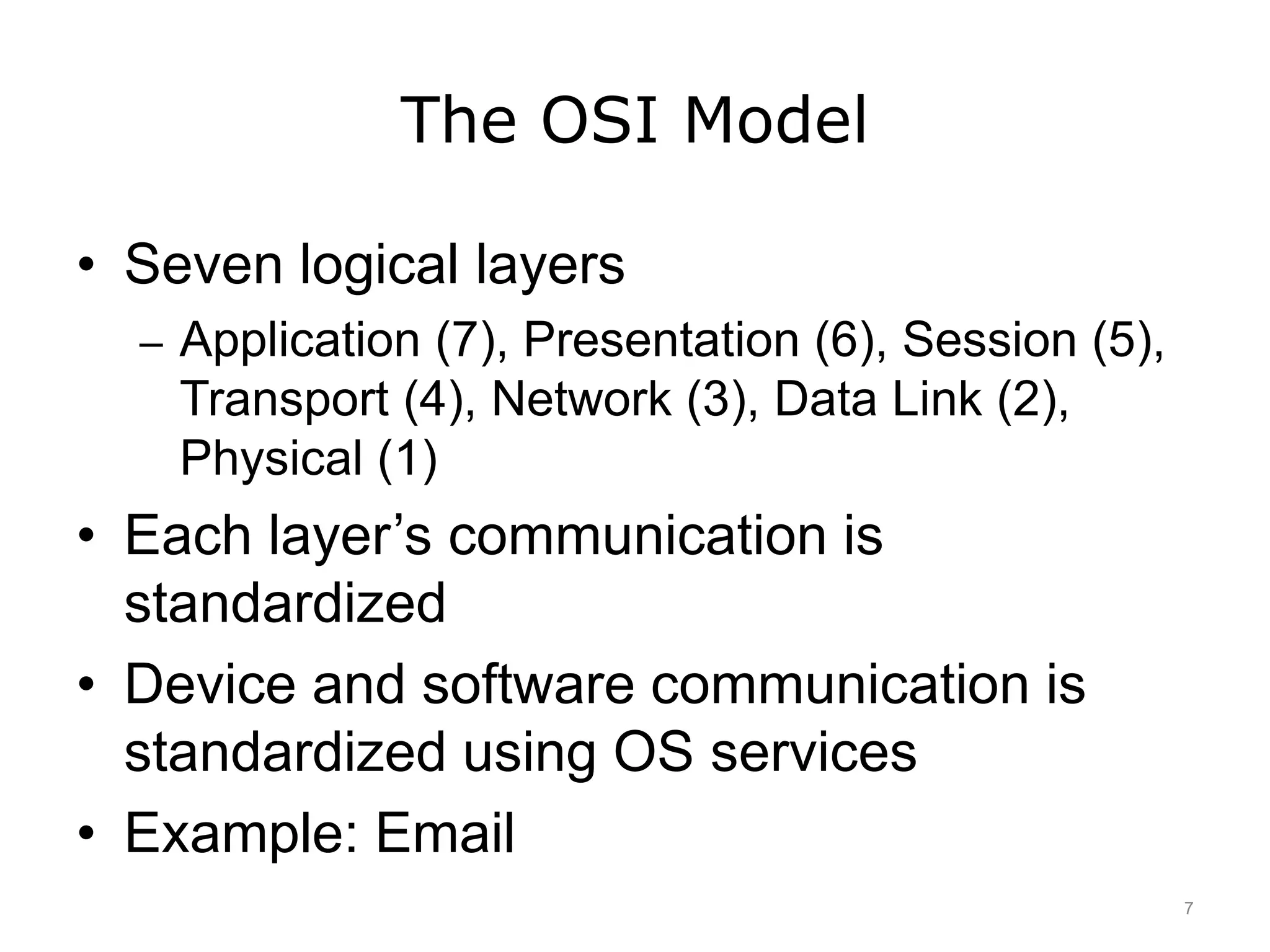
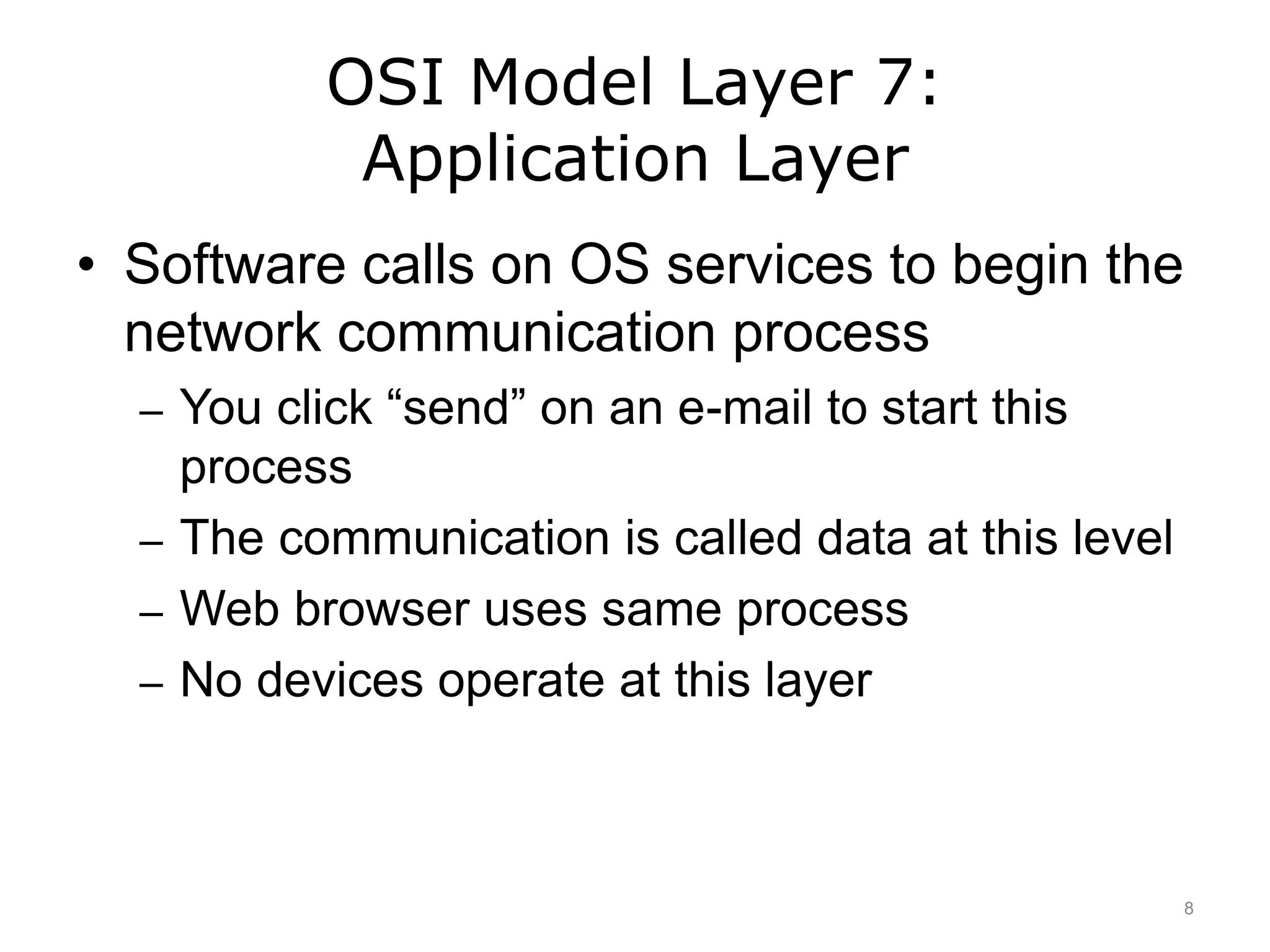
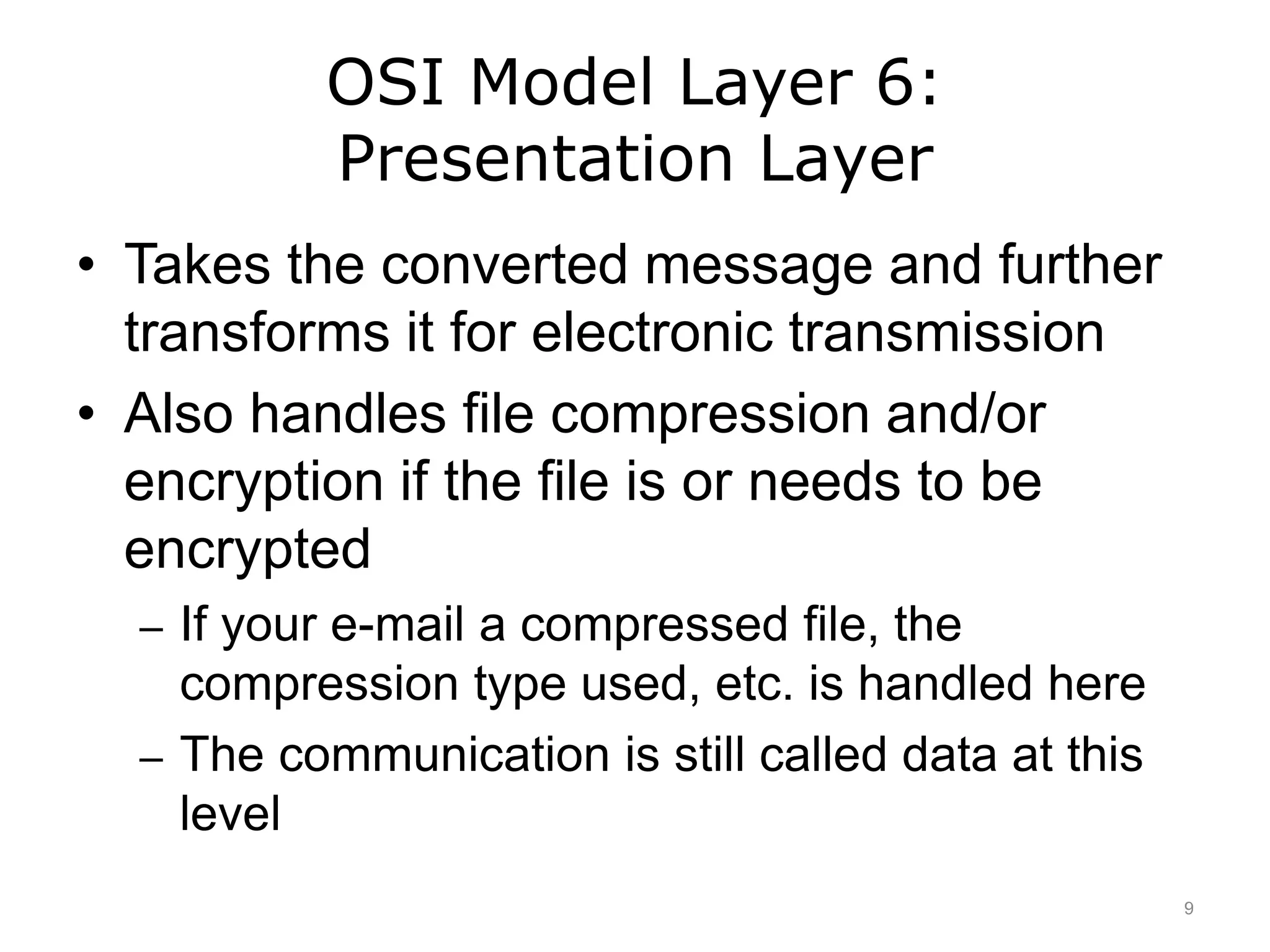
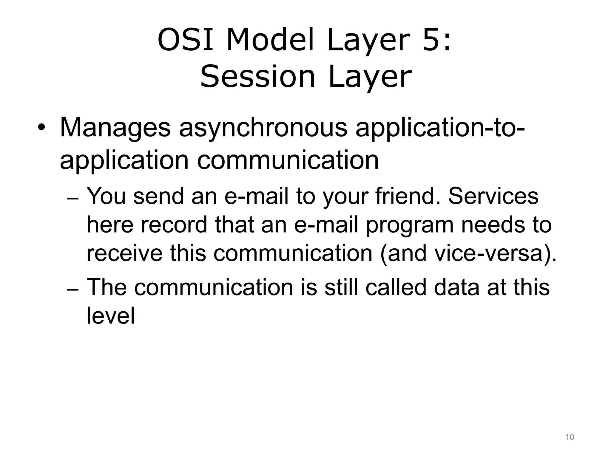
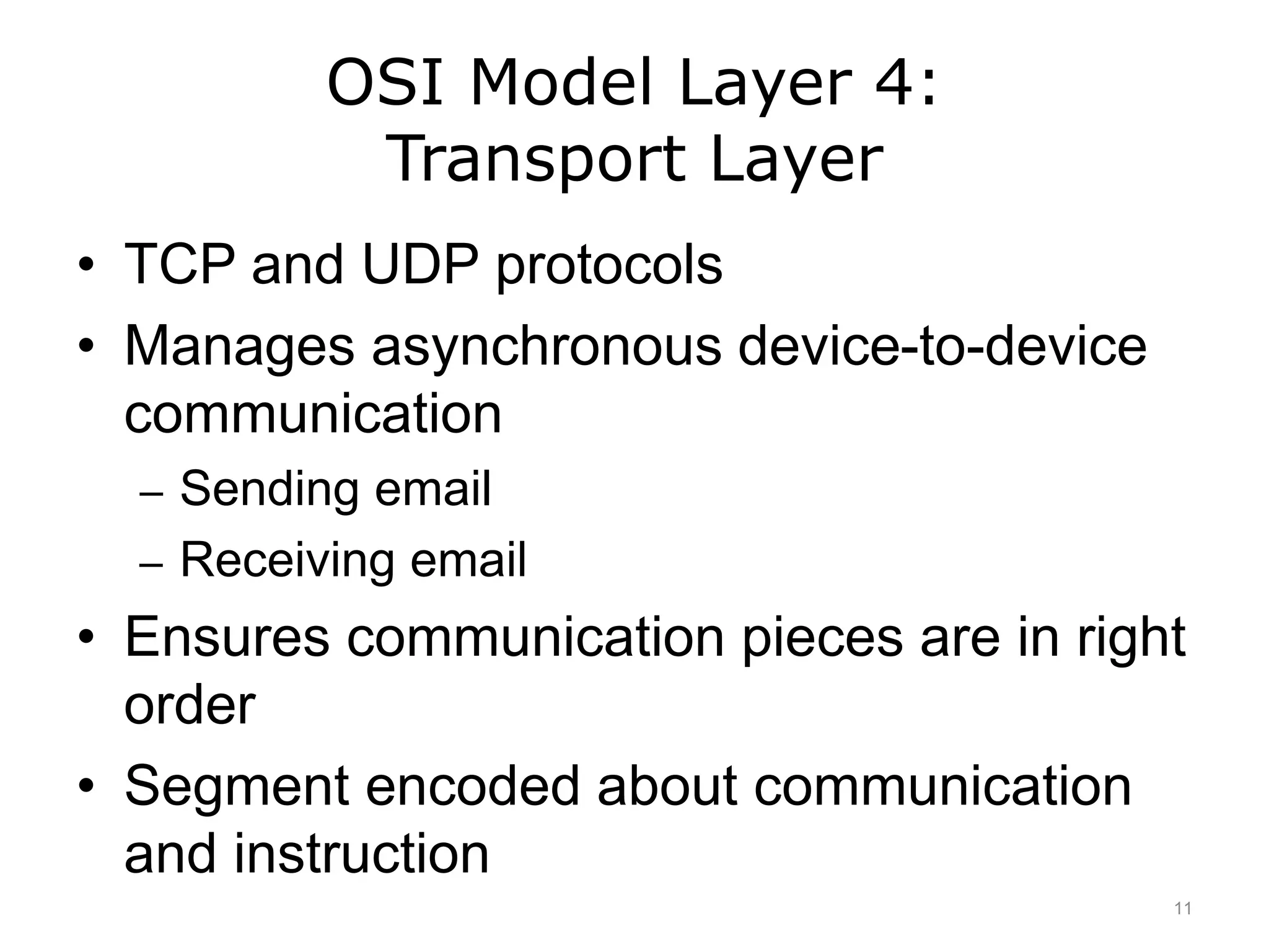
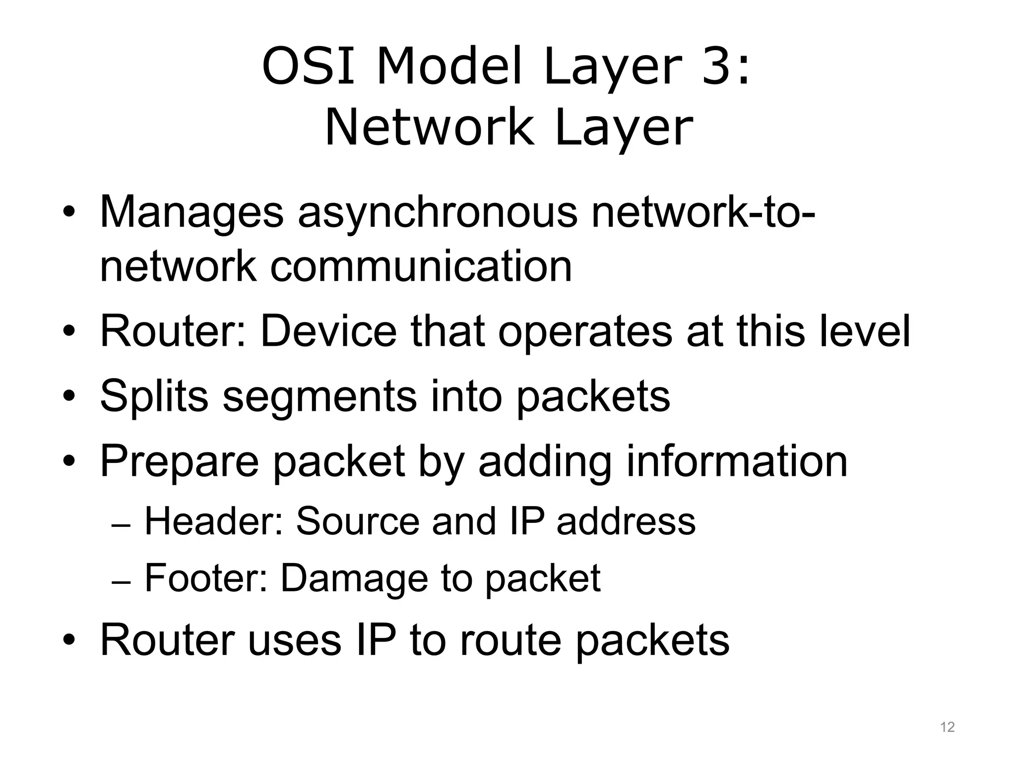
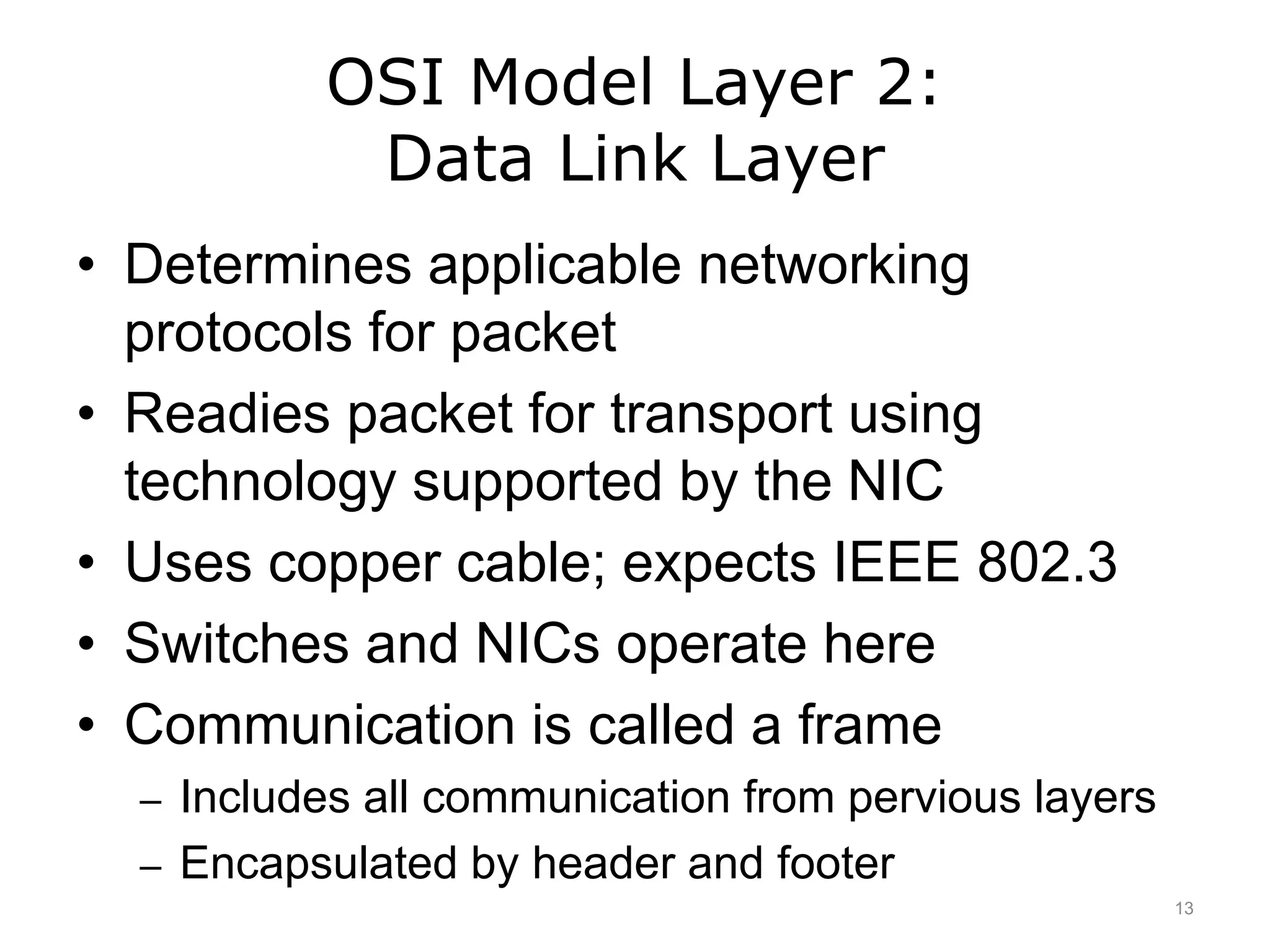
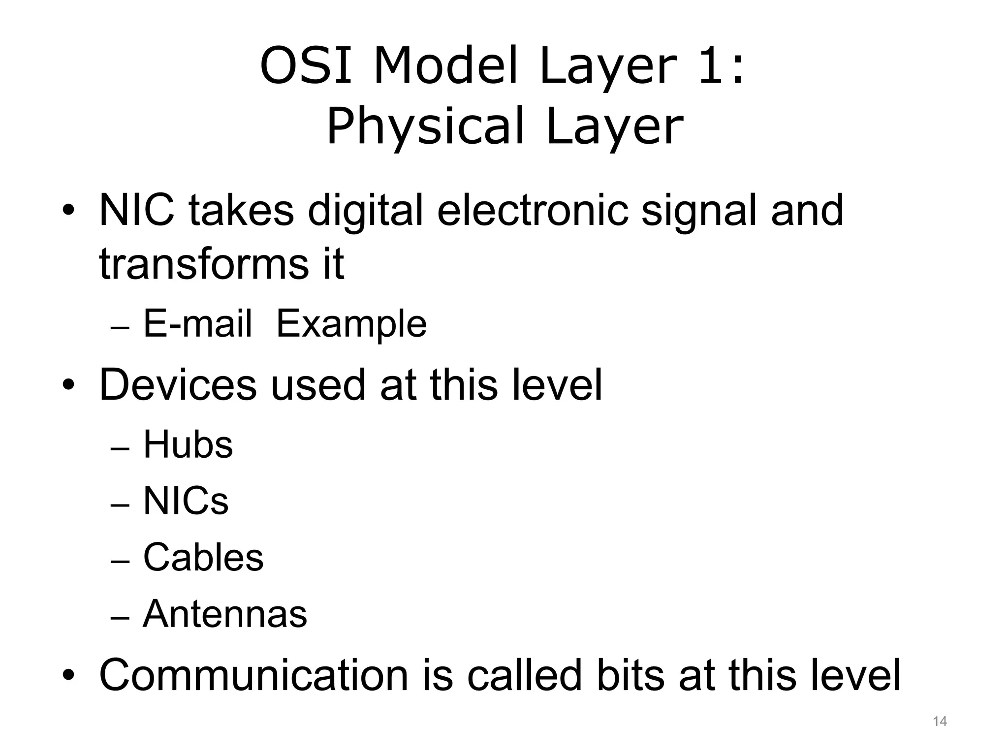
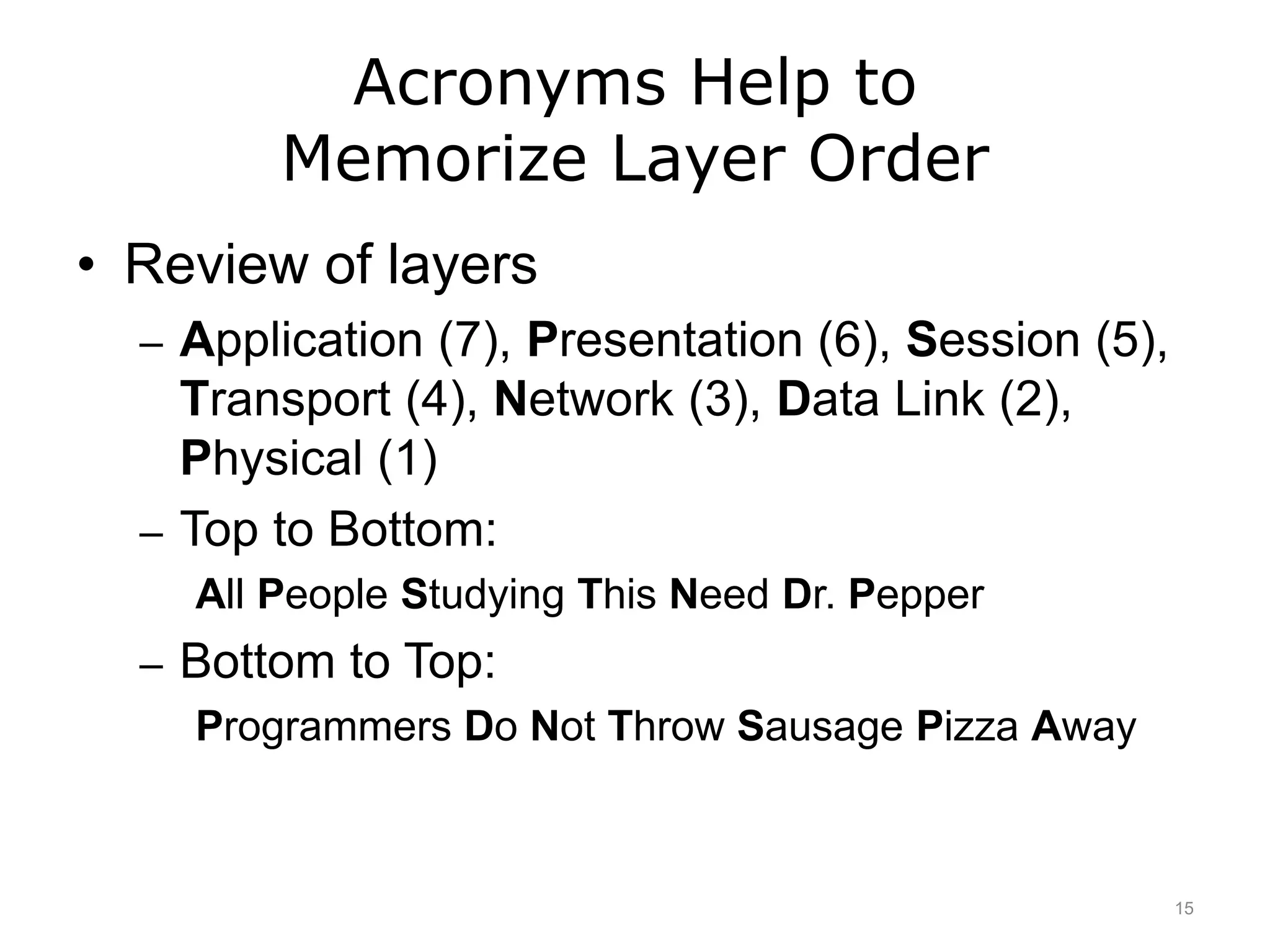
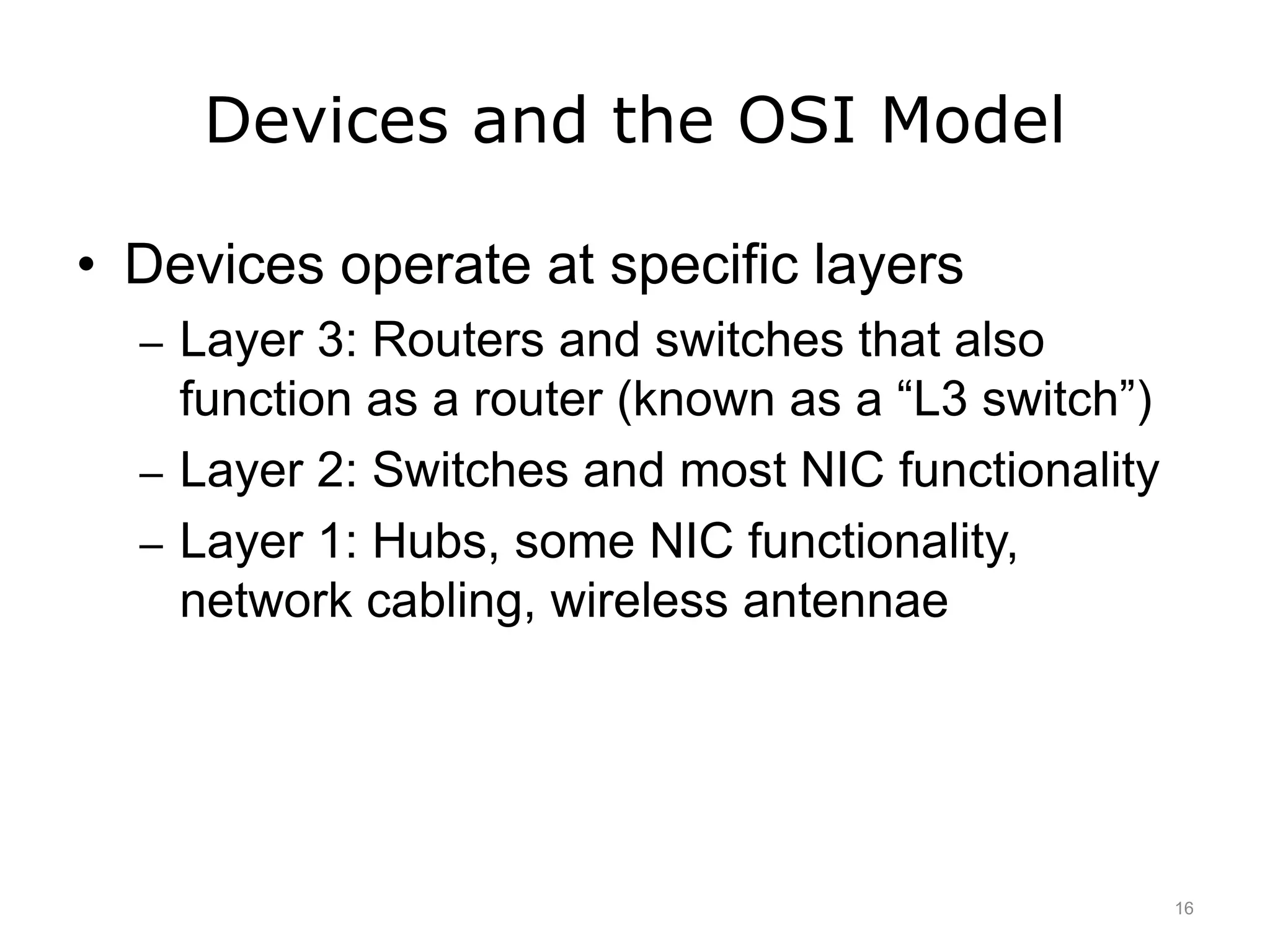
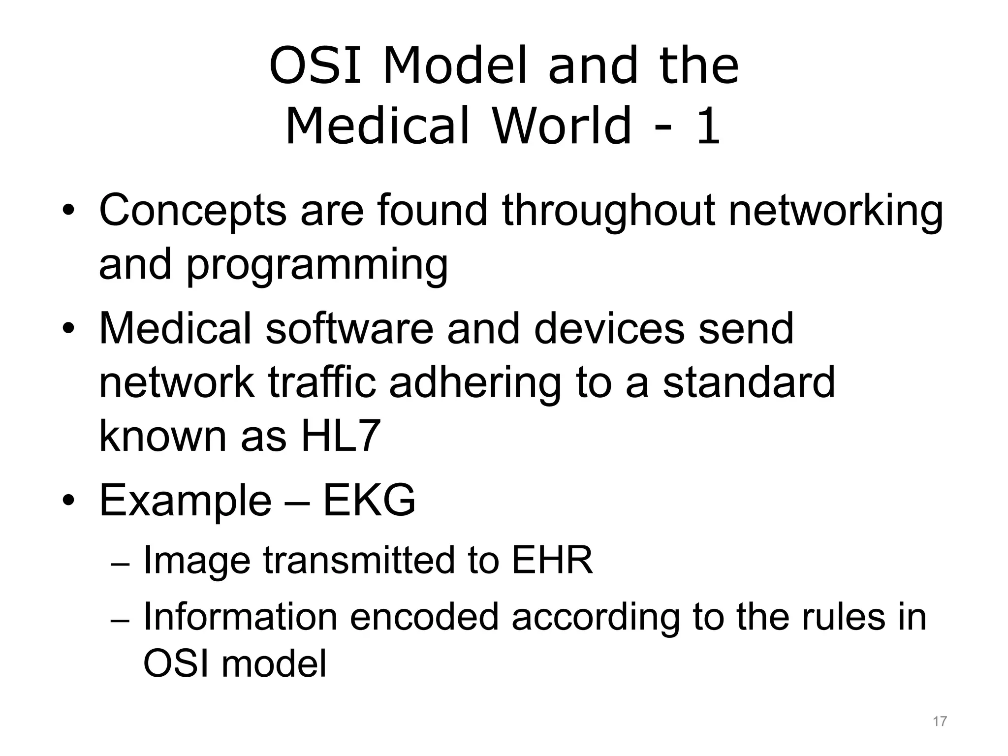
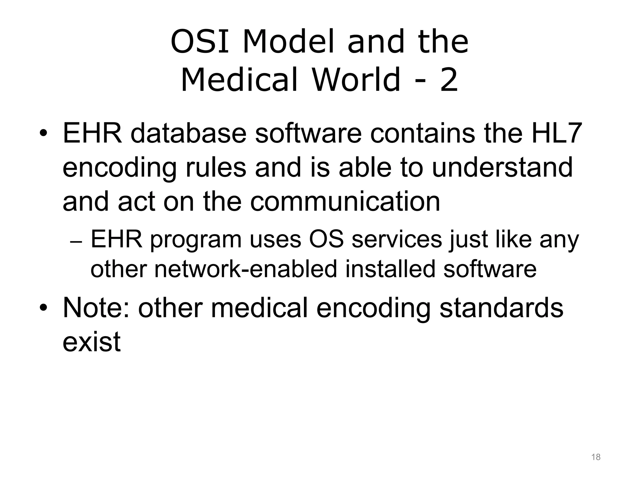
Introduction to Computer Science
Networks
Lecture e
This material (Comp 4 Unit 6) was developed by Oregon Health & Science University, funded by the Department
of Health and Human Services, Office of the National Coordinator for Health Information Technology under
Award Number 90WT0001.
This work is licensed under the Creative Commons Attribution-NonCommercial-ShareAlike 4.0 International
License. To view a copy of this license, visit http://creativecommons.org/licenses/by-nc-sa/4.0/.
Learning Objectives - 1
• Define what a communication network is
(Lecture a)
• Explain the purposes and benefits of a
communication network. (Lecture a)
• Explain the Internet and World Wide Web,
their histories, and their structures.
(Lecture a)
• Describe different ways of connecting to
the Internet. (Lecture a)
2
Learning Objectives - 2
• Explain the basics of network addressing
– Internet Protocol (IP) addresses
– Domain names
– Lease vs. purchase from an Internet service
provider (Lecture b)
• Introduce network classification by the
coverage size. (Lecture b)
3
Learning Objectives - 3
• Describe different network topologies.
(Lecture c)
• Outline different standards and protocols
that govern wired and wireless
communications. (Lecture c)
4
Learning Objectives - 4
• Describe benefits and disadvantages of
wireless communication and a typical
wireless network setup. (Lecture d)
• Describe network hardware. (Lecture d)
• Introduce networking logical models and
discuss Open Systems Interconnection
(OSI) model. (Lecture e)
5
Networking Logical Models
• Devices and software mapped to logical model
to use OS functionality
– OS programs load when computer boots
– OS services are applications that are always
running in the background
• Composed of a series of layers that defines
specific functionality
• OSI (Open Systems Interconnection) model
defines how network hardware and software
operate
6
The OSI Model
• Seven logical layers
– Application (7), Presentation (6), Session (5),
Transport (4), Network (3), Data Link (2),
Physical (1)
• Each layer’s communication is
standardized
• Device and software communication is
standardized using OS services
• Example: Email
7
OSI Model Layer 7:
Application Layer
• Software calls on OS services to begin the
network communication process
– You click “send” on an e-mail to start this
process
– The communication is called data at this level
– Web browser uses same process
– No devices operate at this layer
8
OSI Model Layer 6:
Presentation Layer
• Takes the converted message and further
transforms it for electronic transmission
• Also handles file compression and/or
encryption if the file is or needs to be
encrypted
– If your e-mail a compressed file, the
compression type used, etc. is handled here
– The communication is still called data at this
level
9
OSI Model Layer 5:
Session Layer
• Manages asynchronous application-to-
application communication
– You send an e-mail to your friend. Services
here record that an e-mail program needs to
receive this communication (and vice-versa).
– The communication is still called data at this
level
10
OSI Model Layer 4:
Transport Layer
• TCP and UDP protocols
• Manages asynchronous device-to-device
communication
– Sending email
– Receiving email
• Ensures communication pieces are in right
order
• Segment encoded about communication
and instruction
11
OSI Model Layer 3:
Network Layer
• Manages asynchronous network-to-
network communication
• Router: Device that operates at this level
• Splits segments into packets
• Prepare packet by adding information
– Header: Source and IP address
– Footer: Damage to packet
• Router uses IP to route packets
12
OSI Model Layer 2:
Data Link Layer
• Determines applicable networking
protocols for packet
• Readies packet for transport using
technology supported by the NIC
• Uses copper cable; expects IEEE 802.3
• Switches and NICs operate here
• Communication is called a frame
– Includes all communication from pervious layers
– Encapsulated by header and footer
13
OSI Model Layer 1:
Physical Layer
• NIC takes digital electronic signal and
transforms it
– E-mail Example
• Devices used at this level
– Hubs
– NICs
– Cables
– Antennas
• Communication is called bits at this level
14
Acronyms Help to
Memorize Layer Order
• Review of layers
– Application (7), Presentation (6), Session (5),
Transport (4), Network (3), Data Link (2),
Physical (1)
– Top to Bottom:
All People Studying This Need Dr. Pepper
– Bottom to Top:
Programmers Do Not Throw Sausage Pizza Away
15
Devices and the OSI Model
• Devices operate at specific layers
– Layer 3: Routers and switches that also
function as a router (known as a “L3 switch”)
– Layer 2: Switches and most NIC functionality
– Layer 1: Hubs, some NIC functionality,
network cabling, wireless antennae
16
OSI Model and the
Medical World - 1
• Concepts are found throughout networking
and programming
• Medical software and devices send
network traffic adhering to a standard
known as HL7
• Example – EKG
– Image transmitted to EHR
– Information encoded according to the rules in
OSI model
17
OSI Model and the
Medical World - 2
• EHR database software contains the HL7
encoding rules and is able to understand
and act on the communication
– EHR program uses OS services just like any
other network-enabled installed software
• Note: other medical encoding standards
exist
18
Networks
Summary - Lecture e
• Discussed OSI networking model
– Explained specific functionality for device or
software
19
Networks – Summary
• Communication network
• History of Internet and World Wide Web
• Network connections
– Wired
– Wireless
• Network topologies
• OSI model
20
Networks
References – Lecture e
References
Wikipedia. [Internet]. 2011 Nov [cited 2011 Nov 07]. Available from:
http://en.wikipedia.org/wiki/OSI_model.
21
Introduction to Computer Science
Networks
Lecture e
This material was developed by Oregon
Health & Science University, funded by the
Department of Health and Human Services,
Office of the National Coordinator for Health
Information Technology under Award
Number 90WT0001.
22

Networks - Lecture E

  • 1.
    Introduction to ComputerScience Networks Lecture e This material (Comp 4 Unit 6) was developed by Oregon Health & Science University, funded by the Department of Health and Human Services, Office of the National Coordinator for Health Information Technology under Award Number 90WT0001. This work is licensed under the Creative Commons Attribution-NonCommercial-ShareAlike 4.0 International License. To view a copy of this license, visit http://creativecommons.org/licenses/by-nc-sa/4.0/.
  • 2.
    Learning Objectives -1 • Define what a communication network is (Lecture a) • Explain the purposes and benefits of a communication network. (Lecture a) • Explain the Internet and World Wide Web, their histories, and their structures. (Lecture a) • Describe different ways of connecting to the Internet. (Lecture a) 2
  • 3.
    Learning Objectives -2 • Explain the basics of network addressing – Internet Protocol (IP) addresses – Domain names – Lease vs. purchase from an Internet service provider (Lecture b) • Introduce network classification by the coverage size. (Lecture b) 3
  • 4.
    Learning Objectives -3 • Describe different network topologies. (Lecture c) • Outline different standards and protocols that govern wired and wireless communications. (Lecture c) 4
  • 5.
    Learning Objectives -4 • Describe benefits and disadvantages of wireless communication and a typical wireless network setup. (Lecture d) • Describe network hardware. (Lecture d) • Introduce networking logical models and discuss Open Systems Interconnection (OSI) model. (Lecture e) 5
  • 6.
    Networking Logical Models •Devices and software mapped to logical model to use OS functionality – OS programs load when computer boots – OS services are applications that are always running in the background • Composed of a series of layers that defines specific functionality • OSI (Open Systems Interconnection) model defines how network hardware and software operate 6
  • 7.
    The OSI Model •Seven logical layers – Application (7), Presentation (6), Session (5), Transport (4), Network (3), Data Link (2), Physical (1) • Each layer’s communication is standardized • Device and software communication is standardized using OS services • Example: Email 7
  • 8.
    OSI Model Layer7: Application Layer • Software calls on OS services to begin the network communication process – You click “send” on an e-mail to start this process – The communication is called data at this level – Web browser uses same process – No devices operate at this layer 8
  • 9.
    OSI Model Layer6: Presentation Layer • Takes the converted message and further transforms it for electronic transmission • Also handles file compression and/or encryption if the file is or needs to be encrypted – If your e-mail a compressed file, the compression type used, etc. is handled here – The communication is still called data at this level 9
  • 10.
    OSI Model Layer5: Session Layer • Manages asynchronous application-to- application communication – You send an e-mail to your friend. Services here record that an e-mail program needs to receive this communication (and vice-versa). – The communication is still called data at this level 10
  • 11.
    OSI Model Layer4: Transport Layer • TCP and UDP protocols • Manages asynchronous device-to-device communication – Sending email – Receiving email • Ensures communication pieces are in right order • Segment encoded about communication and instruction 11
  • 12.
    OSI Model Layer3: Network Layer • Manages asynchronous network-to- network communication • Router: Device that operates at this level • Splits segments into packets • Prepare packet by adding information – Header: Source and IP address – Footer: Damage to packet • Router uses IP to route packets 12
  • 13.
    OSI Model Layer2: Data Link Layer • Determines applicable networking protocols for packet • Readies packet for transport using technology supported by the NIC • Uses copper cable; expects IEEE 802.3 • Switches and NICs operate here • Communication is called a frame – Includes all communication from pervious layers – Encapsulated by header and footer 13
  • 14.
    OSI Model Layer1: Physical Layer • NIC takes digital electronic signal and transforms it – E-mail Example • Devices used at this level – Hubs – NICs – Cables – Antennas • Communication is called bits at this level 14
  • 15.
    Acronyms Help to MemorizeLayer Order • Review of layers – Application (7), Presentation (6), Session (5), Transport (4), Network (3), Data Link (2), Physical (1) – Top to Bottom: All People Studying This Need Dr. Pepper – Bottom to Top: Programmers Do Not Throw Sausage Pizza Away 15
  • 16.
    Devices and theOSI Model • Devices operate at specific layers – Layer 3: Routers and switches that also function as a router (known as a “L3 switch”) – Layer 2: Switches and most NIC functionality – Layer 1: Hubs, some NIC functionality, network cabling, wireless antennae 16
  • 17.
    OSI Model andthe Medical World - 1 • Concepts are found throughout networking and programming • Medical software and devices send network traffic adhering to a standard known as HL7 • Example – EKG – Image transmitted to EHR – Information encoded according to the rules in OSI model 17
  • 18.
    OSI Model andthe Medical World - 2 • EHR database software contains the HL7 encoding rules and is able to understand and act on the communication – EHR program uses OS services just like any other network-enabled installed software • Note: other medical encoding standards exist 18
  • 19.
    Networks Summary - Lecturee • Discussed OSI networking model – Explained specific functionality for device or software 19
  • 20.
    Networks – Summary •Communication network • History of Internet and World Wide Web • Network connections – Wired – Wireless • Network topologies • OSI model 20
  • 21.
    Networks References – Lecturee References Wikipedia. [Internet]. 2011 Nov [cited 2011 Nov 07]. Available from: http://en.wikipedia.org/wiki/OSI_model. 21
  • 22.
    Introduction to ComputerScience Networks Lecture e This material was developed by Oregon Health & Science University, funded by the Department of Health and Human Services, Office of the National Coordinator for Health Information Technology under Award Number 90WT0001. 22

Editor's Notes

  • #2 Welcome to Introduction to Computer Science: Networks. This is Lecture e. The component, Introduction to Computer Science, provides a basic overview of computer architecture; data organization, representation, and structure; structure of programming languages; and networking and data communication. It also includes some basic terminology from the world of computing.
  • #3 The objectives for this unit on Networks are to: Define what a communication network is, Explain the purposes and benefits of a communication network, Explain the Internet and World Wide Web, their histories, and their structures, Describe different ways of connecting to the Internet,
  • #4 Explain basics of network addressing: IP addresses and domain names, and how they can be leased or purchased from an Internet service provider. Introduce network classification by the coverage size.
  • #5 Describe different network topologies. Outline different standards and protocols that govern wired and wireless communications.
  • #6 Describe benefits and disadvantages of wireless communication and a typical wireless network setup. Describe network hardware. And, finally, to introduce networking logical models and discuss Open Systems Interconnection, or OSI model.
  • #7 This lecture will explain the OSI networking model that future programmers and database experts need to understand, along with specific functionality for specific devices or software. When hardware and software are created, the engineers need to understand how the devices and software are going to be programmed. The operating system follows a logical model that facilitates communication between hardware and software. A logical model is composed of a series of logical layers that define specific functionality for a device or for a piece of software. The open systems interconnections, or OSI, model defines how network hardware and software operate.
  • #8 The OSI model is composed of seven logical layers. The top layer, layer seven, is the Application, followed by the layers Presentation, Session, Transport, Network, Data Link, and Physical. The Physical layer is always layer one and the Application layer is always layer 7. Each layer's communication is standardized so that adjacent layers know how to communicate with each other. In other words, layer seven has the ability to communicate with layer six. Likewise, layer six has the ability to communicate with layer five AND layer seven. Layer five can communicate with layer four and layer six, and so on. Therefore, device and software communication is standardized by operating system services. Remember that a service is simply a program that starts when the operating system loads. When a computer boots, the boot process loads a number of operating system services. Depending on the device and/or software, one service calls on the functionality of another service to facilitate network functionality and communication. To understand how hardware and software use operating system services let’s look at the example of creating and sending an email message. First, you open the email application. Then you start a new message. You type what you want to say, and you send the email. The email application needs operating system services to take the email from what is seen on the screen and make it in to an electronic equivalent that can be sent out via the computer's network interface card, or NIC. Many operating system services work together to accomplish this task. Services operate within specific OSI logical layers. One service can operate in many layers, depending on what it is doing at any moment in time. Services call on each other as the email works its way towards the NIC via the motherboard circuitry. The NIC calls on services to encode the email for transport out of its port or over the air through an antenna. Then, when the next device, such as a switch or router or even an email server, receives the email electronically, the receiving device uses its hardware and services to process the email. The next few slides will examine each of the layers of the OSI model in a little more detail.
  • #9 In the OSI model, layer seven is known as the Application layer. Software installed in a device calls on the OS services to begin the network communication process by converting the software's communication into a format that can be readied for transmission. For example, clicking Send in our email example starts this process. Note that the communication is data at this level. A web browser, or any network-enabled program, goes through the same process every time a user visits a web page. This is the same process that a smart phone uses to operate. No devices operate at layer seven, because this is where software works on behalf of hardware. Layer seven is closest to the user, so this is where email is originated. However, if the example centered on the user’s computer receiving an email, the discussion would begin at layer one, which is where the NIC receives electronic signals.
  • #10 OSI model layer six is the Presentation layer. No devices operate at layer six because this is where software works on behalf of hardware, just like layer seven. At layer six, the converted message received from layer seven is further transformed for electronic transmission. Layer six also handles file compression and encryption when needed. If a user emails a compressed file, the compression type, for example ZIP, is handled here. Note that the communication is still called data at this level.
  • #11 At OSI model layer five, the Session layer manages asynchronous application-to-application communication. When you send an email message, services at this layer record that an email program needs to receive this communication. Note that the communication is still called data at this level. The term “asynchronous” means that the sender and the receiver do not need to communicate at the same time. No devices operate at layer five because again, this is where software works on behalf of hardware, just like the Application and Presentation layers. Again, the communication is still called data at this level.
  • #12 OSI model layer four is the Transport layer. As in the Application, Presentation, and Session layers, no devices operate at layer four because this is still where software works on behalf of hardware. The transmission control protocol, or TCP, suite of protocols operate at this layer, as does the user datagram protocol, or UDP. The Transport layer manages asynchronous device-to-device communication. For example, when sending an email, services here indicate where a file and the actual communication begin. When receiving an email, the services also indicate where a file ends, and when the communication process should be considered complete. It also ensures that pieces of the communication are put in the right order, whether sending or receiving communication. At the Transport layer, the communication is a segment, encoded with information about the communication and instructions.
  • #13 Next is OSI model layer three, known as the Network layer. This layer manages asynchronous network-to-network communication. Services split the segment into manageable sizes called packets and then further encode each packet with information used by layer three devices. A router is an example of a device that operates at layer three. Services prepare the packet for traffic by adding to each packet electronic pieces of information, including a header and footer. Information stored in the header includes the source and destination IP address. The footer contains the result of a mathematical calculation that helps devices determine damage to the packet. Services inform receiving devices about the packet's source, its destination, protocol, and more. The Internet protocol, or IP, operates at this layer. Routers use IP addressing to route packets to their final destination. TCP does not operate at this level. It becomes operable in layer four, the Transport layer. Finally, at the Network layer of the OSI model, the communication is a packet.
  • #14 OSI model layer two, the Data Link layer, determines applicable networking protocols for this packet. At the same time, layer two services ready the packet for transport using whatever technology the NIC supports. Examples include Ethernet, wireless, fiber-optic, or a combination of these technologies. The computer's NIC may use copper cable and expects a communication encoded according to the Ethernet standard, the IEEE 802.3 standard. Switches and NICs are examples of devices that operate at layer two. Therefore, media access control, or MAC, addressing applies, and MAC addresses are used for communications between layer two devices. Note that the communication is a frame at this level. The frame includes all of the communication received from layers seven through three and is encapsulated by a header and footer.
  • #15 At OSI model layer one, known as the Physical layer, the NIC takes the computer's digital electronic signal and transforms it into a signal that can be put on the NIC's media. Therefore, an email translates into electronic impulses and moves from the NIC to the wires at the end of the RJ45 connector, which is at the end of a network cable. The electronic impulses are bits, or binary digits. The bits transmit across the entire cable length to the next device, which is usually a switch or router. Hubs, NICs, cables, and antennas are examples of devices that operate at layer one. NICs operate in both layers one and two of the OSI layer, but primarily at layer two. Finally, note that the communication at layer one is a bit.
  • #16 At this point, the OSI model, its layers, and the functionality that occurs at each layer may seem overwhelming. Fortunately, there is a way to help memorize the layer order of the OSI model. Here is a mnemonic to help remember the seven layers from top to bottom: All People Studying This Need Dr. Pepper Or, if you prefer, from bottom to top: Programmers Do Not Throw Sausage Pizza Away Take some time for review to remember each of the layers of the OSI model, and perhaps construct a one-sentence explanation about the functionality of each layer. Anyone who plans to work with routers, switches, or servers will most likely need to know more about the OSI model and its services. A deeper understanding of the OSI model is beyond the scope of this discussion.
  • #17 As discussed earlier, the OSI model shows that certain devices operate at specific layers. To review, at layer three, routers and switches that function as routers. Such a switch is a layer three switch. Layer two has switches and most NIC functionality. Layer one has hubs, some NIC functionality, network cabling, and then wireless antennae.
  • #18 Why learn about the OSI model? Future programmers and database experts will need to understand how things happen electronically. In fact, concepts related to the OSI model are found throughout networking and programming. Many medical software applications send network traffic adhering to a standard known as Health Level 7, or HL7, named after the OSI model layer seven. An example is an EKG image being transmitted from a machine to the patient's electronic health record, or EHR, encoded in accordance with HL7 rules. In this transaction, the receiving EHR database is informed of the type of image received, the patient record number, equipment identification, supervising clinician, and so on. The information is encoded in this communication, according to the rules discussed in the OSI model.
  • #19 In addition, EHR database software contains HL7 encoding rules and is able to understand and act on the communication received from the EKG machine. Therefore, the EHR program uses operating system services just like any other network-enabled software.
  • #20 This concludes lecture e of the unit on Networks. In summary, this lecture covered the OSI networking model that future programmers and database experts will need to understand. It also discussed specific functionality for specific devices or software.
  • #21 That also concludes the unit on Networks. To review, in this unit we explored the concept of a communication network, examined the history of the Internet and World Wide Web, investigated both wired and wireless network connections, identified various network topologies, and introduced the open systems interconnection model.
  • #22 References slide. No audio.
  • #23 No audio.