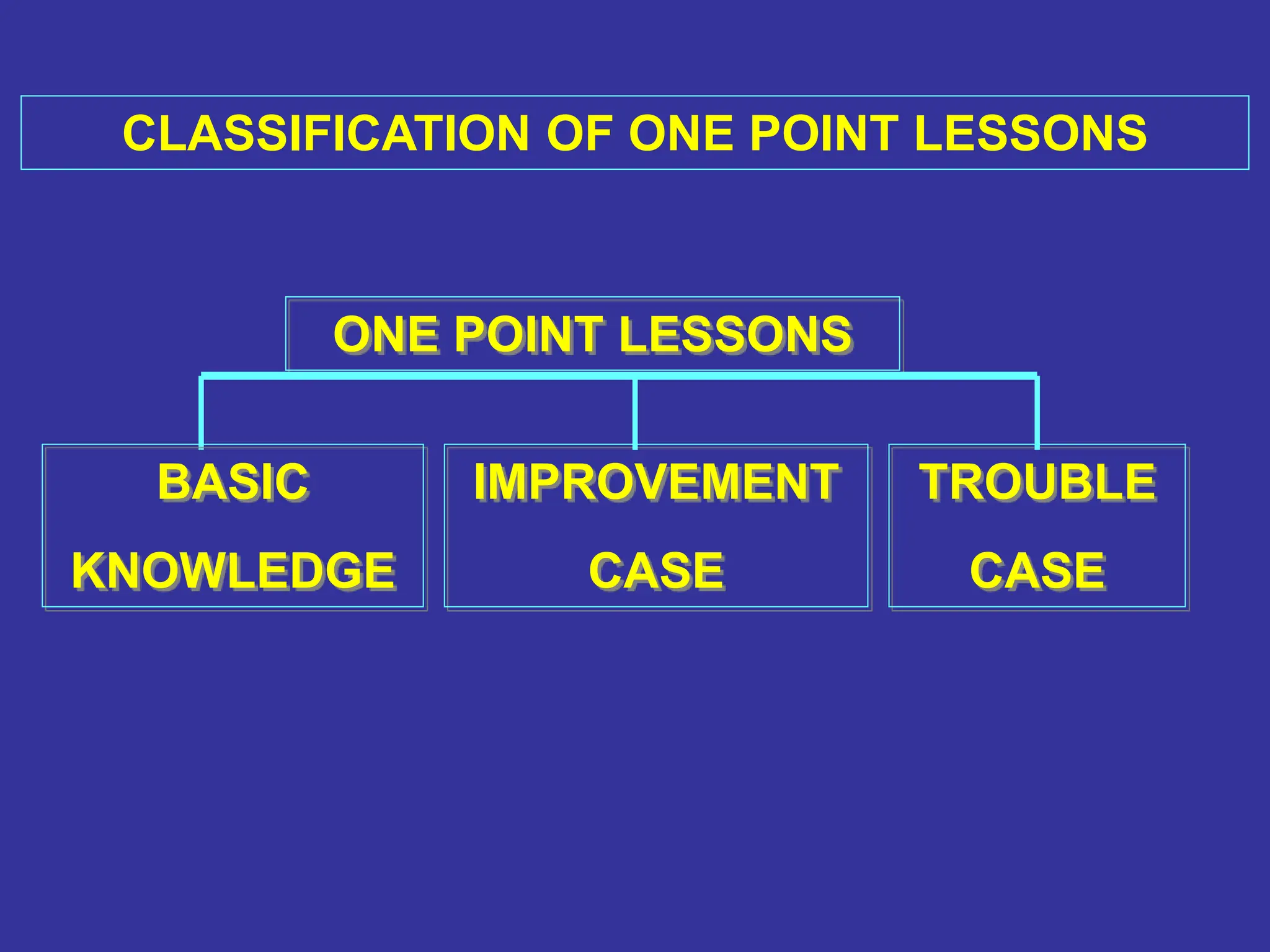
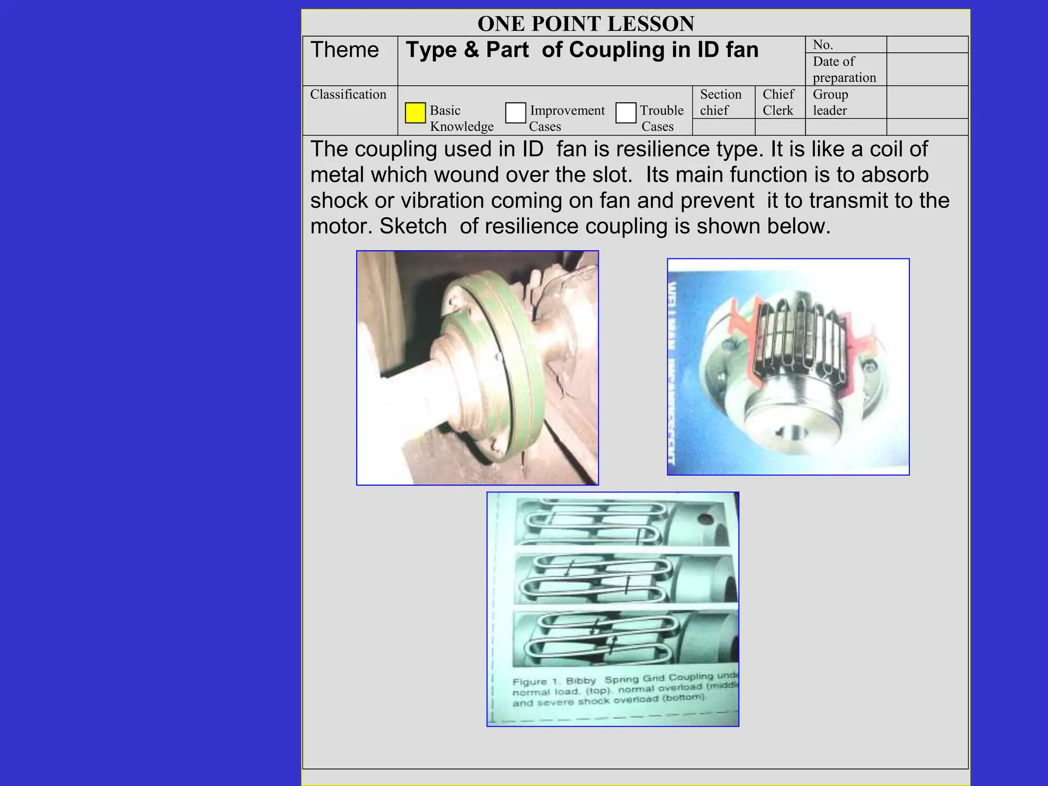
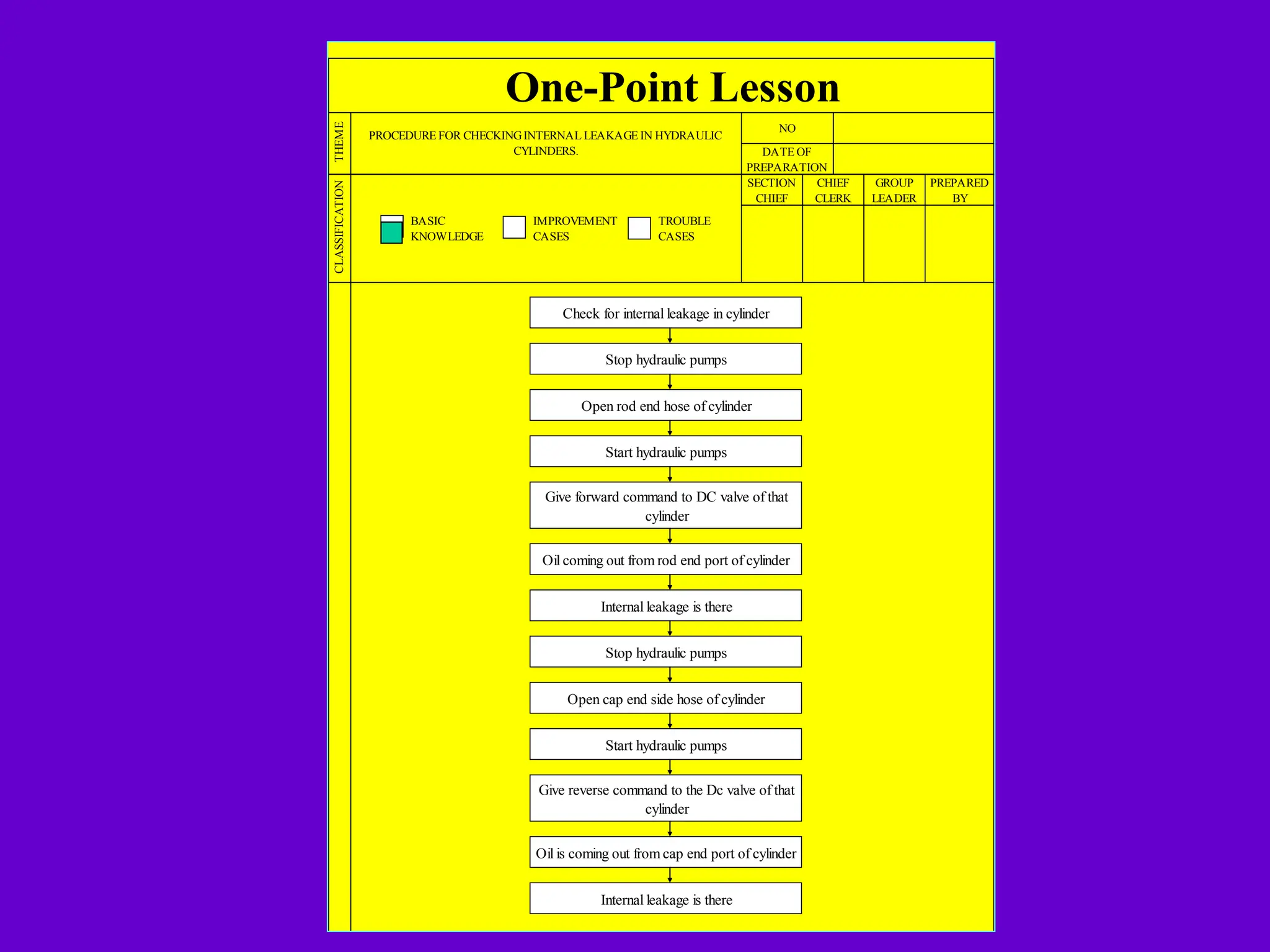
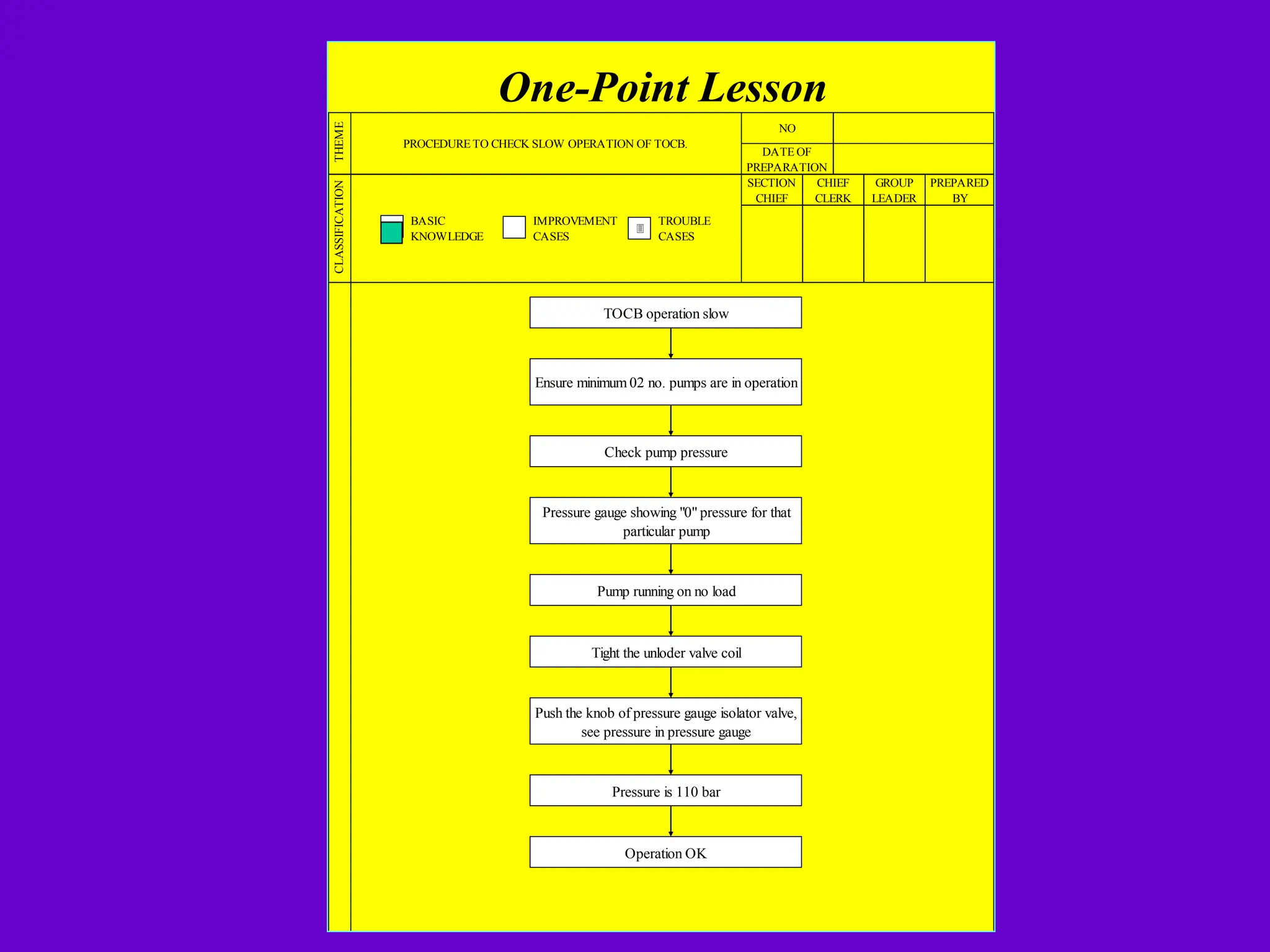
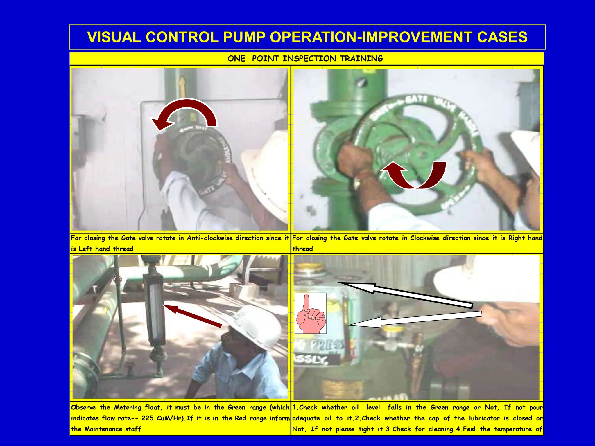
ONE POINT LESSON
 ONE POINT LESSON - GENERAL INTRODUCTION
 ONE POINT LESSONS - EXAMPLES
 ONE POINT LESSONS - RESULTS
One Point Lesson
GENERAL
ONE POINT LESSON
ONE POINT LESSONS IS A SIMPLE
KNOWLEDGE & SKILLS SHARING SHEET
WHICH FOCUSES ON ONLY ONE KEY
POINT OF IMPORTANCE AT A TIME , E.G. OF
A PARTICULAR PART/ITEM OF A MACHINE,
MORE BY USE OF VISUALIZATION THAN BY
USE OF LARGE TEXT.
ONE POINT LESSONS OBJECTIVES
FACILITATES:
 ENHANCES THE KNOWLEDGE AND SKILLS
IN A SHORT PERIOD OF TIME.
 EASY UNDERSTANDING OF MACHINE
FUNCTIONS / COMPONENTS.
ONE POINT LESSONS OBJECTIVES
FACILITATES:
 CREATES SIMPLE KNOWLEDGE SHARING
SYSTEM & NEW TEACHING ASPECTS
WITH CLEAR UNDERSTANDING OF
CONCEPTS
 SKILL ENHANCEMENT OF INSPECTION /
IMPERFECTION IDENTIFICATION
CLASSIFICATION OF ONE POINT LESSONS
ONE POINT LESSONS
BASIC
KNOWLEDGE
TROUBLE
CASE
IMPROVEMENT
CASE
One Point Lesson
EXAMPLES- BASIC KNOWLEDGE
ONE POINT LESSON
No.
Theme
PART & TYPE OF BEARING IN
ID FAN
Date of
preparation
Section
chief
Chief
Clerk
Group
leader
Prepared
By
Classification
Basic Improvement Trouble
Knowledge Cases Cases
Bearing used in ID Fan is ball bearing type which consist
of inner race ,outer race ,rolling element ( ball )and cage .
Figure show the bearing used in our fan
INNER RACE
CAGE
BALL
OUTER RACE
ONE POINT LESSON
No.
Theme Type & Part of Coupling in ID fan Date of
preparation
Section
chief
Chief
Clerk
Group
leader
Classification
Basic Improvement Trouble
Knowledge Cases Cases
The coupling used in ID fan is resilience type. It is like a coil of
metal which wound over the slot. Its main function is to absorb
shock or vibration coming on fan and prevent it to transmit to the
motor. Sketch of resilience coupling is shown below.
MAJOR FAN PARTS ARE :-
1. FAN CASING
2. IMPELLER
3. SHAFT
4. HUB
HUB
Damper
HU
B
VAN
Shaft
Impeller
CASING
BASIC KNOWLEDGE ON ID FANS PART
Sr.No
Date of
Preparation
Div/Dept.
Head
Group Leader
SPANNER/WRENCH
L
Theme
Classification
Basic Knowledge Improvement Cases Trouble Cases
Appropriate Tightening & Re-tightening
Adequate tightening force to be
applied to avoid loosening.
Re-tightening is carried out to
bring back a loosened Bolt
(caused by vibration or shock )
to its original tightness.
For Loosening of Bolt Spanner/Wrench is
to be rotated in the ANTI-CLOCK-WISE
direction
2
Torque
(Kg-cm)
Tightening/Loosening is to be
done by pulling Spanner/Wrench
towards the body.
Not exceeding the yield point
even if an external force, such
as vibration or shock, is
applied .
Position of Spanner & Wrench should be
always perpendicular to the vertical axis of
the Nut & Bolt.
3
For tightening/Re-tightening
Spanner/Wrench is to be rotated in
the CLOCK-WISE direction
4
1
Key points/Why
Re-tightening is not tightening
beyond the original torque .
RE-TIGHTENING
APPROPRIATE TIGHTENING
Work Procedure Requirements
Spanner
Vertical
Axis
Spann
Sr.No
Date of
Preparation
Div/Dept.
Head
Group Leader
Maintains performance through oiling
with lubricating oil suited to the
machine
If excessive, an excessive amount of
lubricating oil is mixed in, causing the
oil temperature to rise and foam to
appear. As a result, deterioration
advances,causing a drop in viscosity
and lubrication defects.
APPROPRIATE METHOD
APPROPRIATE TIME
APPROPRIATE OIL
3
Classification
Basic Knowledge Improvement Cases Trouble Cases
Theme
Correct Method of Oiling
Know /Why
Working Instruction
1 Use the appropriate lubricating oil Performance is maintained by oiling
with a lubrication oil suited to the
machine .
4
If inadequate , an oil film oil film
cannot be formed on lubricating
surfaces, causing problem , which
leads to expenses for parts
replacement.
2
Apply only the standard amount of oil
When the oil level falls the lower limit,
air is sucked in, causing a loss of film
on lubricated parts and resulting in
abnormal wear
Perform at appropriate periods, such as when
supplementing oil or making replacements
Adopt the proper lubrication method
APPROPRIATE QUANTITY
F -> Filter
Removes impurities like dust and dirt , water drops
R -> Pressure regulator
It,s function is to maintain the pressure at the required value
L -> Lubricator ( Oiler )
Device supplies lubricating oil to the cylinder and valve, with air flow .
FRL UNIT
F
L
R
BASIC KNOWLEDGE ON FRL UNITS
Equipment Picture
Roll & it's
Accessories
Roll
Brg. Sleeve
Laby.Ring
Taper Sleeve
BASIC KNOWLEDGE ON
MILL ROLL & ACCESSORIES
CONSTRUCTION OF BEVEL GEAR BOX
INPUT
OUTPUT
GEAR
BASIC KNOWLEDGE ON BEVEL GEAR
S.N.
1
2
3
4
5
6
7
DC Motor operation
BEARING 6,330
Voltage 700 V
Speed 600/1500 RPM
Current 764 A
TECHNICAL DETAILS/MACHINE SPECIFICATION
DETAILS
Type DC
PART NAME
MOTOR PARTS DETAILS
PART NUMBER
Unit
Value
Rated Power 500 KW
Make Kirlosker
Pressure gauge & Hx cooling water line
Pulse Techo
CONSTRUCTION OF MOTOR
PRINCIPLE
1
2
3
4
Motor
Heat Exchanger
1
2
3
4
BASIC KNOWLEDGE ON
DC MOTOR AT MILL
VALVES
Gate Valve Non Return Valve
This is connected to the discharge side of pump and is used to regulate the
flow of fluid.
Generally it is connected connected above the gate valve at the
discharge side. It is connected in such a way that when the pump
stops,the fluid in the piping at the discharge side does not flow
backward.
BASIC KNOWLEDGE ON VALVE
Patm
FORCE
UNIT AREA
In SI unit system :- pascal ( N/m2
)
P
In MKS unit system :- kgf/m2
Pressures are also stated in terms mm or cm of mercury.
76 - 16
76
1 bar = 105
N/m2
= 100 KN/mm2
= 100 kPa
Absolute pressure : - The pressure relative to perfect vacuum is called Absolute
pressure.
What is VACUUM ?
Absolute pressure = Gauge pressure+Atmospheric pressure
Since,it is a very large unit in comparision with many engineering values, kgf/cm
2
is
used.It is also known as ata( atmospheric technical absolute ).
1 standard atmosphere = 760 mm Hg =
1.01325 bar = 101.325 Kn/mm
2
=1.0332 ata =1.0332
kgf/cm2
Important Terminology
Gauge pressure : - The pressure relative to atmosphere is called Gauge pressure.
When the pressure in a system is less than atmospheric pressure, the gauge pressure
becomes negative, but is frequently designated by a positive number and called
VACUUM.For example, 16 cm vacuum will be----
X 1.013 = 0.80 bar
Above pressure gauge is based on the principle of Bourdon gauge which
measures the difference between the system pressure inside the tube
and atmospheric pressure. It relies on the deformation of a bent hollow
tube of suitable material which, when subject
PRESSURE AND PRESSURE GAUGE
Pressure Pressure Gauge
Pressure is the normal force exerted by a system against unit area of its bounding
surface.
PRESSURE =
Unit system of Pressure
Since, it is very small unit, generally another unit called bar,kPa or Mpa is used.
U N I T
AR EA
F
O
R
C
E
BASIC KNOWLEDGE ON
PRESSURE GAUGE
One-Point Lesson
THEME
STOPPING OF I.D FANS
NO
DATE OF
PREPARATION
CHIEF
CLERK
CLASSIFICATION
GROUP
LEADER
PREPARED
BY
BASIC
KNOWLEDGE
IMPROVEMENT
CASES
TROUBLE
CASES
SECTION
CHIEF
3
STOP THE ID FAN BY
OPERATING MOTOR "OFF"
SWITCH.
CLOSE THE INLET DAMPER
VALVE.
CLOSE THE OUTLET DAMPER
VALVE.
CHECK PHYSICALLY THAT BOTH
THE INLET AND OULET DAMPER
VALVE IS FULLY CLOSED.
One-Point Lesson
THEME
STARTING OF I.D FANS (FES-II)
NO
DATE OF
PREPARATION
CHIEF
CLERK
CLASSIFICATION
GROUP
LEADER
PREPARED
BY
BASIC
KNOWLEDGE
IMPROVEMENT
CASES
TROUBLE
CASES
SECTION
CHIEF
3
BEFORE STARTING ENSURE THAT INLET DAMPER VALVE IS
FULLY CLOSED.
OPEN THE OUTLET DAMPER VALVE BY OPERATING
PNEUMATIC CYLINDER D.C VALVE.
ENSURE THAT ALL THE INSPECTION COVERS ARE PROPERLY
TIGHTENED.
START THE THE I.D FAN BY OPERATING MOTOR "ON"
SWITCH.
ADJUST THE INLET DAMPER VALVE WITH RESPECT TO ID
FAN MOTOR CURRENT WHICH SHOULD NOT EXCEED MORE
THAN 450 Amp. CURRENT.
PREPARED
BY
BASIC
KNOWLEDGE
IMPROVEMENT
CASES
TROUBLE
CASES
CLASSIFICATION
SECTION
CHIEF
CHIEF
CLERK
GROUP
LEADER
One-Point Lesson
THEME
PROCEDURE FOR WORKING ON
HYDRAULIC SYSTEM.
NO
DATE OF
PREPARATION
3
Working on hydraulic system
Stop hydraulic pumps
Close valves at suction of pumps to ensure
no running of pump during working
Connect minimess hose with pressure
gauge to the minimess coupling
Check pressure of system is zero or not
If not, operate DC valve manually
See pressure, it must be zero
Now start working on the system
After completion of job open the valve at
suction of pump
Start hydraulic pumps
Ensure zero leakage of oil for system
PREPARED
BY
BASIC
KNOWLEDGE
IMPROVEMENT
CASES
TROUBLE
CASES
CLASSIFICATION
SECTION
CHIEF
CHIEF
CLERK
GROUP
LEADER
One-Point Lesson
THEME
PROCEDURE FOR CHECKINGINTERNAL LEAKAGE IN HYDRAULIC
CYLINDERS.
NO
DATE OF
PREPARATION
3
Check for internal leakage in cylinder
Stop hydraulic pumps
Open rod end hose of cylinder
Start hydraulic pumps
Give forward command to DC valve of that
cylinder
Oil coming out from rod end port of cylinder
Internal leakage is there
Stop hydraulic pumps
Open cap end side hose of cylinder
Start hydraulic pumps
Give reverse command to the Dc valve of that
cylinder
Oil is coming out from cap end port of cylinder
Internal leakage is there
One-Point Lesson
THEME
NO
DATE OF
PREPARATION
CLASSIFICATION
SECTION
CHIEF
CHIEF
CLERK
GROUP
LEADER
PROCEDURE TO CHECK SLOW OPERATION OF TOCB.
PREPARED
BY
BASIC
KNOWLEDGE
IMPROVEMENT
CASES
TROUBLE
CASES
3
TOCB operation slow
Ensure minimum 02 no. pumps are in operation
Check pump pressure
Pressure gauge showing "0" pressure for that
particular pump
Pump running on no load
Tight the unloder valve coil
Push the knob of pressure gauge isolator valve,
see pressure in pressure gauge
Pressure is 110 bar
Operation OK
One Point Lesson
EXAMPLES - IMPROVEMENT CASES
For closing the Gate valve rotate in Anti-clockwise direction since it
is Left hand thread
ONE POINT INSPECTION TRAINING
For closing the Gate valve rotate in Clockwise direction since it is Right hand
thread
Observe the Metering float, it must be in the Green range (which
indicates flow rate-- 225 CuM/Hr).If it is in the Red range inform
the Maintenance staff.
1.Check whether oil level falls in the Green range or Not, If not pour
adequate oil to it.2.Check whether the cap of the lubricator is closed or
Not, If not please tight it.3.Check for cleaning.4.Feel the temperature of
lubricator.
VISUAL CONTROL PUMP OPERATION-IMPROVEMENT CASES
2.Is there any abnormal sound.( Please use your ear to hear).
3.Is the Bearing temperature high ? ( Please touch with hand )
Inspect through the sight window whether 3-4 drops of oil
transfers per minute or not, If not adjust the Needle valve by
closing or opening the Knob. Check the Solenoid coil temperature by
hand & check for oil leakage and cleaning.
Inspect whether the Needle is in the Green range or Not. If not inform the
Maintenance staff
1. Are there any Vibration ? ( Use hand to feel, If it is not possible then
use a screw driver )
VISUAL CONTROL VT PUMP OPERATION -
Oper a t i o n - - - BACK WASH I N G
Open slowly the backwash inlet valve to introduce water & wait till
water overflows through the air vent.
Close air vent valve
ONE POINT FILTER OPERATION TRAINING
BACKWASH SWITCH PANEL
BACK WASH PUMP
Step-2
Step-1
Step-3 Step-4
VISUAL CONTROL PUMP OPERATION -IMPROVEMENT CASES
Section
chief
Chief
Clerk
Group
leader Prepared By
Classification Basic Improvement Trouble
Knowledge Cases Cases
PHYSICAL INSPECTION OF TUBES INSIDE BOILER IS DONE BY TOUCHING THE
EVAPORATOR TUBES BY HAND AT BEND, TOP AND BOTTOM PORTION FOR EROSION OF
TUBES AND STUDES ON TUBES. TUBES FOUND ERODED ARE TO BE REPLACED BY NEW
TUBES.
BED EVAPORATOR TUBE
INSTALLED INSIDE BOILER IN
NEW CONDITION
INSPECTION OF COIL
AT BEND PORTION
INSPECTION OF
COIL AT STRAIGHT
TOP PORTION
INSPECTION OF
COIL AT STRAIGHT
BOTTOM PORTION
PARENT MATERIAL OF TUBES
STUDES PROVIDED ON BED
TUBES TO REDUCE EROSION
HOW TO DO PHYSICAL INSPECTION OF BED TUBES
BOILER TUBE VISUAL INSPECTION

ONE POINT LESSONS-part1 .ppt, OPL TPM JH

  • 1.
  • 2.
     ONE POINTLESSON - GENERAL INTRODUCTION  ONE POINT LESSONS - EXAMPLES  ONE POINT LESSONS - RESULTS
  • 3.
  • 4.
    ONE POINT LESSON ONEPOINT LESSONS IS A SIMPLE KNOWLEDGE & SKILLS SHARING SHEET WHICH FOCUSES ON ONLY ONE KEY POINT OF IMPORTANCE AT A TIME , E.G. OF A PARTICULAR PART/ITEM OF A MACHINE, MORE BY USE OF VISUALIZATION THAN BY USE OF LARGE TEXT.
  • 5.
    ONE POINT LESSONSOBJECTIVES FACILITATES:  ENHANCES THE KNOWLEDGE AND SKILLS IN A SHORT PERIOD OF TIME.  EASY UNDERSTANDING OF MACHINE FUNCTIONS / COMPONENTS.
  • 6.
    ONE POINT LESSONSOBJECTIVES FACILITATES:  CREATES SIMPLE KNOWLEDGE SHARING SYSTEM & NEW TEACHING ASPECTS WITH CLEAR UNDERSTANDING OF CONCEPTS  SKILL ENHANCEMENT OF INSPECTION / IMPERFECTION IDENTIFICATION
  • 7.
    CLASSIFICATION OF ONEPOINT LESSONS ONE POINT LESSONS BASIC KNOWLEDGE TROUBLE CASE IMPROVEMENT CASE
  • 8.
  • 9.
    ONE POINT LESSON No. Theme PART& TYPE OF BEARING IN ID FAN Date of preparation Section chief Chief Clerk Group leader Prepared By Classification Basic Improvement Trouble Knowledge Cases Cases Bearing used in ID Fan is ball bearing type which consist of inner race ,outer race ,rolling element ( ball )and cage . Figure show the bearing used in our fan INNER RACE CAGE BALL OUTER RACE
  • 10.
    ONE POINT LESSON No. ThemeType & Part of Coupling in ID fan Date of preparation Section chief Chief Clerk Group leader Classification Basic Improvement Trouble Knowledge Cases Cases The coupling used in ID fan is resilience type. It is like a coil of metal which wound over the slot. Its main function is to absorb shock or vibration coming on fan and prevent it to transmit to the motor. Sketch of resilience coupling is shown below.
  • 11.
    MAJOR FAN PARTSARE :- 1. FAN CASING 2. IMPELLER 3. SHAFT 4. HUB HUB Damper HU B VAN Shaft Impeller CASING BASIC KNOWLEDGE ON ID FANS PART
  • 12.
    Sr.No Date of Preparation Div/Dept. Head Group Leader SPANNER/WRENCH L Theme Classification BasicKnowledge Improvement Cases Trouble Cases Appropriate Tightening & Re-tightening Adequate tightening force to be applied to avoid loosening. Re-tightening is carried out to bring back a loosened Bolt (caused by vibration or shock ) to its original tightness. For Loosening of Bolt Spanner/Wrench is to be rotated in the ANTI-CLOCK-WISE direction 2 Torque (Kg-cm) Tightening/Loosening is to be done by pulling Spanner/Wrench towards the body. Not exceeding the yield point even if an external force, such as vibration or shock, is applied . Position of Spanner & Wrench should be always perpendicular to the vertical axis of the Nut & Bolt. 3 For tightening/Re-tightening Spanner/Wrench is to be rotated in the CLOCK-WISE direction 4 1 Key points/Why Re-tightening is not tightening beyond the original torque . RE-TIGHTENING APPROPRIATE TIGHTENING Work Procedure Requirements Spanner Vertical Axis Spann
  • 13.
    Sr.No Date of Preparation Div/Dept. Head Group Leader Maintainsperformance through oiling with lubricating oil suited to the machine If excessive, an excessive amount of lubricating oil is mixed in, causing the oil temperature to rise and foam to appear. As a result, deterioration advances,causing a drop in viscosity and lubrication defects. APPROPRIATE METHOD APPROPRIATE TIME APPROPRIATE OIL 3 Classification Basic Knowledge Improvement Cases Trouble Cases Theme Correct Method of Oiling Know /Why Working Instruction 1 Use the appropriate lubricating oil Performance is maintained by oiling with a lubrication oil suited to the machine . 4 If inadequate , an oil film oil film cannot be formed on lubricating surfaces, causing problem , which leads to expenses for parts replacement. 2 Apply only the standard amount of oil When the oil level falls the lower limit, air is sucked in, causing a loss of film on lubricated parts and resulting in abnormal wear Perform at appropriate periods, such as when supplementing oil or making replacements Adopt the proper lubrication method APPROPRIATE QUANTITY
  • 14.
    F -> Filter Removesimpurities like dust and dirt , water drops R -> Pressure regulator It,s function is to maintain the pressure at the required value L -> Lubricator ( Oiler ) Device supplies lubricating oil to the cylinder and valve, with air flow . FRL UNIT F L R BASIC KNOWLEDGE ON FRL UNITS
  • 15.
    Equipment Picture Roll &it's Accessories Roll Brg. Sleeve Laby.Ring Taper Sleeve BASIC KNOWLEDGE ON MILL ROLL & ACCESSORIES
  • 16.
    CONSTRUCTION OF BEVELGEAR BOX INPUT OUTPUT GEAR BASIC KNOWLEDGE ON BEVEL GEAR
  • 17.
    S.N. 1 2 3 4 5 6 7 DC Motor operation BEARING6,330 Voltage 700 V Speed 600/1500 RPM Current 764 A TECHNICAL DETAILS/MACHINE SPECIFICATION DETAILS Type DC PART NAME MOTOR PARTS DETAILS PART NUMBER Unit Value Rated Power 500 KW Make Kirlosker Pressure gauge & Hx cooling water line Pulse Techo CONSTRUCTION OF MOTOR PRINCIPLE 1 2 3 4 Motor Heat Exchanger 1 2 3 4 BASIC KNOWLEDGE ON DC MOTOR AT MILL
  • 18.
    VALVES Gate Valve NonReturn Valve This is connected to the discharge side of pump and is used to regulate the flow of fluid. Generally it is connected connected above the gate valve at the discharge side. It is connected in such a way that when the pump stops,the fluid in the piping at the discharge side does not flow backward. BASIC KNOWLEDGE ON VALVE
  • 19.
    Patm FORCE UNIT AREA In SIunit system :- pascal ( N/m2 ) P In MKS unit system :- kgf/m2 Pressures are also stated in terms mm or cm of mercury. 76 - 16 76 1 bar = 105 N/m2 = 100 KN/mm2 = 100 kPa Absolute pressure : - The pressure relative to perfect vacuum is called Absolute pressure. What is VACUUM ? Absolute pressure = Gauge pressure+Atmospheric pressure Since,it is a very large unit in comparision with many engineering values, kgf/cm 2 is used.It is also known as ata( atmospheric technical absolute ). 1 standard atmosphere = 760 mm Hg = 1.01325 bar = 101.325 Kn/mm 2 =1.0332 ata =1.0332 kgf/cm2 Important Terminology Gauge pressure : - The pressure relative to atmosphere is called Gauge pressure. When the pressure in a system is less than atmospheric pressure, the gauge pressure becomes negative, but is frequently designated by a positive number and called VACUUM.For example, 16 cm vacuum will be---- X 1.013 = 0.80 bar Above pressure gauge is based on the principle of Bourdon gauge which measures the difference between the system pressure inside the tube and atmospheric pressure. It relies on the deformation of a bent hollow tube of suitable material which, when subject PRESSURE AND PRESSURE GAUGE Pressure Pressure Gauge Pressure is the normal force exerted by a system against unit area of its bounding surface. PRESSURE = Unit system of Pressure Since, it is very small unit, generally another unit called bar,kPa or Mpa is used. U N I T AR EA F O R C E BASIC KNOWLEDGE ON PRESSURE GAUGE
  • 20.
    One-Point Lesson THEME STOPPING OFI.D FANS NO DATE OF PREPARATION CHIEF CLERK CLASSIFICATION GROUP LEADER PREPARED BY BASIC KNOWLEDGE IMPROVEMENT CASES TROUBLE CASES SECTION CHIEF 3 STOP THE ID FAN BY OPERATING MOTOR "OFF" SWITCH. CLOSE THE INLET DAMPER VALVE. CLOSE THE OUTLET DAMPER VALVE. CHECK PHYSICALLY THAT BOTH THE INLET AND OULET DAMPER VALVE IS FULLY CLOSED.
  • 21.
    One-Point Lesson THEME STARTING OFI.D FANS (FES-II) NO DATE OF PREPARATION CHIEF CLERK CLASSIFICATION GROUP LEADER PREPARED BY BASIC KNOWLEDGE IMPROVEMENT CASES TROUBLE CASES SECTION CHIEF 3 BEFORE STARTING ENSURE THAT INLET DAMPER VALVE IS FULLY CLOSED. OPEN THE OUTLET DAMPER VALVE BY OPERATING PNEUMATIC CYLINDER D.C VALVE. ENSURE THAT ALL THE INSPECTION COVERS ARE PROPERLY TIGHTENED. START THE THE I.D FAN BY OPERATING MOTOR "ON" SWITCH. ADJUST THE INLET DAMPER VALVE WITH RESPECT TO ID FAN MOTOR CURRENT WHICH SHOULD NOT EXCEED MORE THAN 450 Amp. CURRENT.
  • 22.
    PREPARED BY BASIC KNOWLEDGE IMPROVEMENT CASES TROUBLE CASES CLASSIFICATION SECTION CHIEF CHIEF CLERK GROUP LEADER One-Point Lesson THEME PROCEDURE FORWORKING ON HYDRAULIC SYSTEM. NO DATE OF PREPARATION 3 Working on hydraulic system Stop hydraulic pumps Close valves at suction of pumps to ensure no running of pump during working Connect minimess hose with pressure gauge to the minimess coupling Check pressure of system is zero or not If not, operate DC valve manually See pressure, it must be zero Now start working on the system After completion of job open the valve at suction of pump Start hydraulic pumps Ensure zero leakage of oil for system
  • 23.
    PREPARED BY BASIC KNOWLEDGE IMPROVEMENT CASES TROUBLE CASES CLASSIFICATION SECTION CHIEF CHIEF CLERK GROUP LEADER One-Point Lesson THEME PROCEDURE FORCHECKINGINTERNAL LEAKAGE IN HYDRAULIC CYLINDERS. NO DATE OF PREPARATION 3 Check for internal leakage in cylinder Stop hydraulic pumps Open rod end hose of cylinder Start hydraulic pumps Give forward command to DC valve of that cylinder Oil coming out from rod end port of cylinder Internal leakage is there Stop hydraulic pumps Open cap end side hose of cylinder Start hydraulic pumps Give reverse command to the Dc valve of that cylinder Oil is coming out from cap end port of cylinder Internal leakage is there
  • 24.
    One-Point Lesson THEME NO DATE OF PREPARATION CLASSIFICATION SECTION CHIEF CHIEF CLERK GROUP LEADER PROCEDURETO CHECK SLOW OPERATION OF TOCB. PREPARED BY BASIC KNOWLEDGE IMPROVEMENT CASES TROUBLE CASES 3 TOCB operation slow Ensure minimum 02 no. pumps are in operation Check pump pressure Pressure gauge showing "0" pressure for that particular pump Pump running on no load Tight the unloder valve coil Push the knob of pressure gauge isolator valve, see pressure in pressure gauge Pressure is 110 bar Operation OK
  • 25.
    One Point Lesson EXAMPLES- IMPROVEMENT CASES
  • 26.
    For closing theGate valve rotate in Anti-clockwise direction since it is Left hand thread ONE POINT INSPECTION TRAINING For closing the Gate valve rotate in Clockwise direction since it is Right hand thread Observe the Metering float, it must be in the Green range (which indicates flow rate-- 225 CuM/Hr).If it is in the Red range inform the Maintenance staff. 1.Check whether oil level falls in the Green range or Not, If not pour adequate oil to it.2.Check whether the cap of the lubricator is closed or Not, If not please tight it.3.Check for cleaning.4.Feel the temperature of lubricator. VISUAL CONTROL PUMP OPERATION-IMPROVEMENT CASES
  • 27.
    2.Is there anyabnormal sound.( Please use your ear to hear). 3.Is the Bearing temperature high ? ( Please touch with hand ) Inspect through the sight window whether 3-4 drops of oil transfers per minute or not, If not adjust the Needle valve by closing or opening the Knob. Check the Solenoid coil temperature by hand & check for oil leakage and cleaning. Inspect whether the Needle is in the Green range or Not. If not inform the Maintenance staff 1. Are there any Vibration ? ( Use hand to feel, If it is not possible then use a screw driver ) VISUAL CONTROL VT PUMP OPERATION -
  • 28.
    Oper a ti o n - - - BACK WASH I N G Open slowly the backwash inlet valve to introduce water & wait till water overflows through the air vent. Close air vent valve ONE POINT FILTER OPERATION TRAINING BACKWASH SWITCH PANEL BACK WASH PUMP Step-2 Step-1 Step-3 Step-4 VISUAL CONTROL PUMP OPERATION -IMPROVEMENT CASES
  • 29.
    Section chief Chief Clerk Group leader Prepared By ClassificationBasic Improvement Trouble Knowledge Cases Cases PHYSICAL INSPECTION OF TUBES INSIDE BOILER IS DONE BY TOUCHING THE EVAPORATOR TUBES BY HAND AT BEND, TOP AND BOTTOM PORTION FOR EROSION OF TUBES AND STUDES ON TUBES. TUBES FOUND ERODED ARE TO BE REPLACED BY NEW TUBES. BED EVAPORATOR TUBE INSTALLED INSIDE BOILER IN NEW CONDITION INSPECTION OF COIL AT BEND PORTION INSPECTION OF COIL AT STRAIGHT TOP PORTION INSPECTION OF COIL AT STRAIGHT BOTTOM PORTION PARENT MATERIAL OF TUBES STUDES PROVIDED ON BED TUBES TO REDUCE EROSION HOW TO DO PHYSICAL INSPECTION OF BED TUBES BOILER TUBE VISUAL INSPECTION