
Recommended
More Related Content
What's hot
What's hot (20)
Similar to LINE FOLLOWING ROBOT
Similar to LINE FOLLOWING ROBOT (20)
Recently uploaded
Recently uploaded (20)
LINE FOLLOWING ROBOT
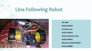
- 1. Oli ullah Id:011143014 Israt jhan eva Id:011143014 Arhana Rahman silvy Id:011143021 Mamunur Rashid Rubel Id:011143005
- 2. Index • Introduction • Components • Working Principle • Block Diagram • Application • Advantages and Disadvantages • Programming on Arduino Let’s Discuss
- 3. Introduction What is a Robot A Robot is a machine capable of carrying out a complex series of actions automatically, especially one programmable by a computer.
- 4. Line Following Robot What is a Line Following Robot Line following Robot is a machine that can follow a path. The path can be visible like a black line on a white surface or it can be invisible like a magnetic field.
- 5. What is the need to build a line follower? Sensing a line and maneuvering the robot to stay on course, while constantly correcting wrong moves using feedback mechanism forms a simple yet effective closed loop system.
- 6. Components •Arduino uno •IR Sensor • Motors L298N •Motors What are we using?
- 7. Arduino Arduino is an open- source computer hardware and software company, project and user community that designs and manufactures microcontroller- based kits for building digital devices.
- 11. Arduino UNO IR Sensor IR Sensor Motor Driver DC motor DC motor Block Diagram IR Sensor
- 12. Circuit Diagram
- 13. IR Sensor
- 14. IR Sensor A passive infrared sensor (PIR sensor) is an electronic sensor that measures infrared (IR) light radiating from objects in its field of view. They are most often used in PIR-based motion detectors.
- 15. IR Working Principle Infrared Spectrum Transmitter Receiver Reflection by Object Voltage
- 16. Object Detection
- 17. The robot uses IR(infrared) sensors to sense the line. Output of the sensors is an analog signal which depends on the amount of light reflected back. This analog signal is given to the comparator to Then microcontroller decides the position of robot in left or right direction. WORKING PRINCIPLE
- 18. WORKING PRINCIPLE When left sensor comes in white(for black line tracer) region then right motor stops while left motor continue to move so that right turn takes place and robot returns on white line. First sensor which is to the right will become low as that sensor will be facing the black line and the remaining sensors response will be high. i.e. the right wheel is held constant and the left wheel is made to move freely until the response from the middle sensor becomes low . When right sensor comes in white region then left motor stops while right motor continue to move so that left turn takes place and robot returns on white line.
- 19. WORKING PRINCIPLE( contd…) 19 The middle sensor will always be on the line and as the line is black in color, it will not reflect the emitted radiation back and the response of the sensor will be low and the response of the remaining two sensors will be high as they will be on the bright surface. When both sensors are on black line then robot moves forward. If all the three sensors will be on brighter surface then they all will be high and as no line is detected , robot move in a circular motion until line is found.
- 20. Applications • Industrial automated equipment carriers. • Automated cars. • Tour guides in museums and other similar applications. • Deliver the mail within the office building • Deliver medications in a hospital. Where is this used?
- 21. Advantages • The robot must be capable of following a line. • Insensitive to environment factors like noise and lightning. • It should be capable of taking various degrees of turns. • The color of the line must not be a factor as long as it is darker than the surroundings.
- 22. Disadvantages • LFR can move on a fixed track or path. • It requires power supply. • Lack of speed control makes the robot unstable at times. • Choice of line is made in the hardware abstraction and cannot be changed by software. What are the disadvantages ?
- 23. Code: const int lmtf =7; const int lmtb=6; const int rmtf =8; const int rmtb=9; const int ENA = 3; const int ENB = 5; void setup() { pinMode(lmtf,OUTPUT); pinMode(lmtb,OUTPUT); pinMode(rmtf,OUTPUT); pinMode(rmtb,OUTPUT); pinMode (ENA, OUTPUT); pinMode (ENB, OUTPUT); // put your setup code here, to run once: } void loop() { int lsensor=digitalRead(11); int fsensor=digitalRead(12); int rsensor=digitalRead(13); analogWrite(ENA, 200); analogWrite(ENB, 200); if(fsensor==HIGH) { digitalWrite(lmtf,HIGH); digitalWrite(lmtb,LOW); digitalWrite(rmtf,HIGH); digitalWrite(rmtb,LOW); } else if(rsensor==HIGH) { digitalWrite(lmtf,LOW); digitalWrite(lmtb,LOW); digitalWrite(rmtf,HIGH); digitalWrite(rmtb,LOW); } else if(lsensor==HIGH) { digitalWrite(lmtf,HIGH); digitalWrite(lmtb,LOW); digitalWrite(rmtf,LOW); digitalWrite(rmtb,LOW); } else { else if(lsensor==HIGH) { digitalWrite(lmtf,HIGH); digitalWrite(lmtb,LOW); digitalWrite(rmtf,LOW); digitalWrite(rmtb,LOW); } else { else if(lsensor==HIGH) { digitalWrite(lmtf,HIGH); digitalWrite(lmtb,LOW); digitalWrite(rmtf,LOW); digitalWrite(rmtb,LOW); } else { digitalWrite(lmtf,LOW); digitalWrite(lmtb,LOW); digitalWrite(rmtf,LOW); digitalWrite(rmtb,LOW);
- 24. QUESTIONS ?????
- 25. Thank You