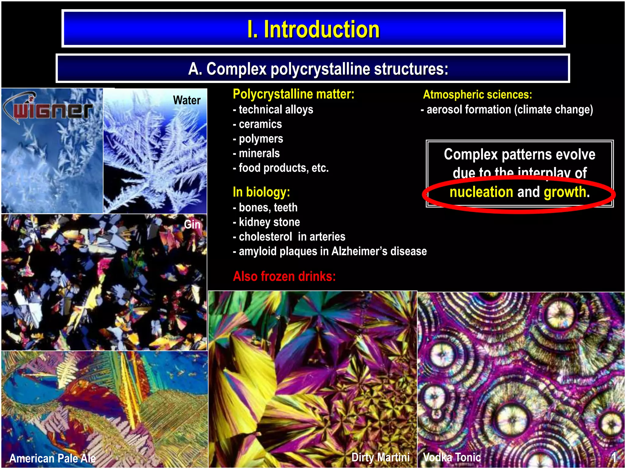
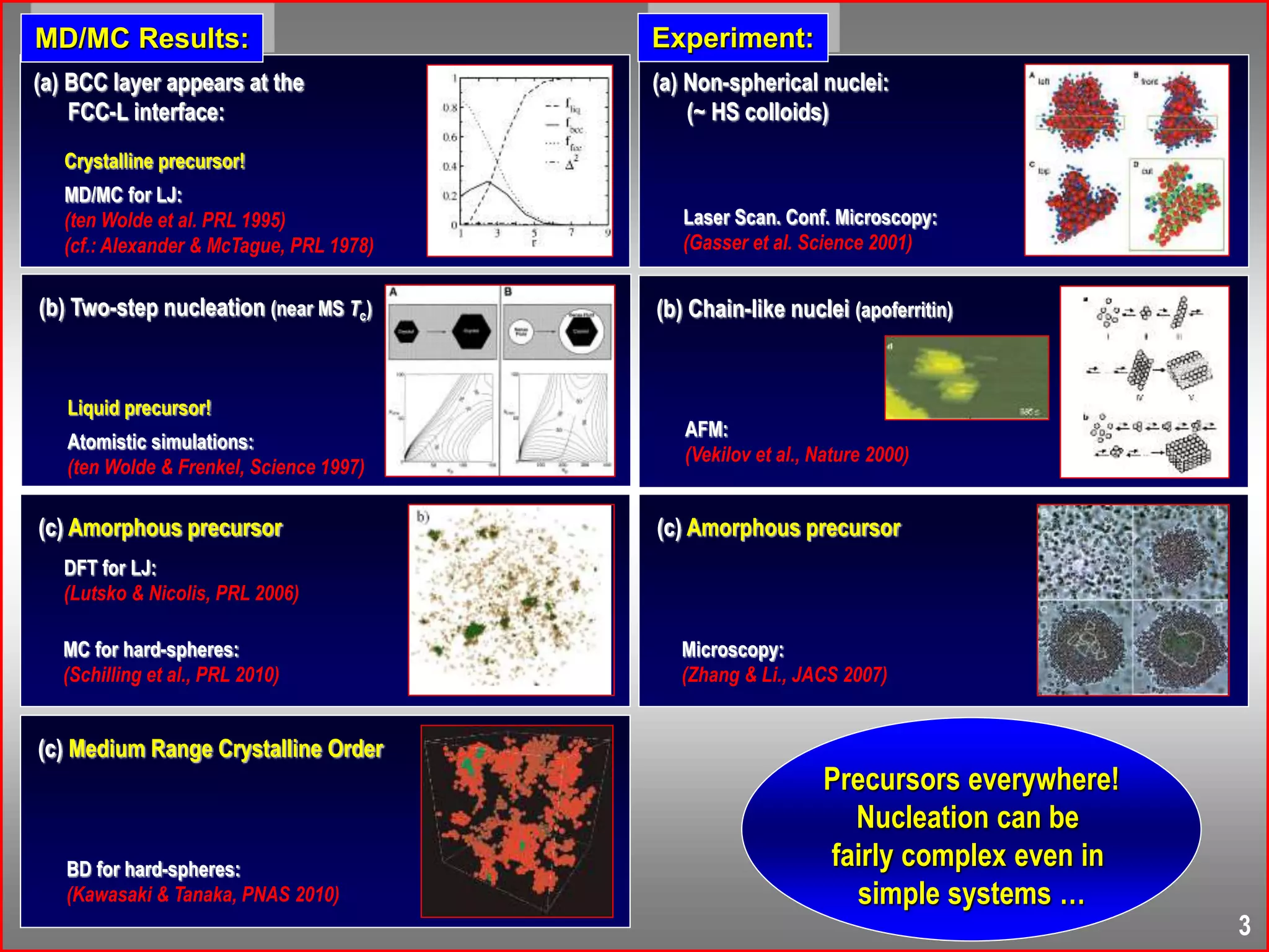
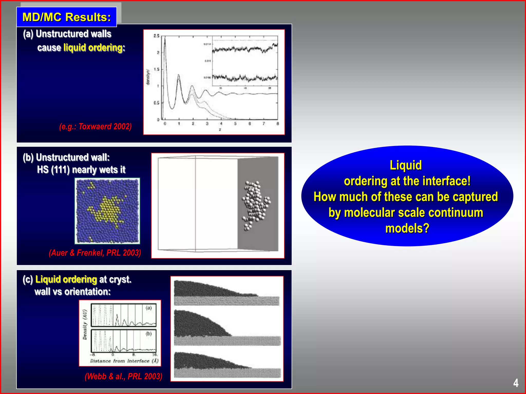
This document summarizes research on modeling nucleation processes using phase-field crystal modeling. It begins with an introduction to complex polycrystalline structures that form through nucleation and growth processes. It then provides an overview of the phase-field crystal approach and how it can be used to model nucleation and growth dynamics. Specific applications discussed include modeling homogeneous and heterogeneous nucleation barriers using the Euler-Lagrange method and simulating non-equilibrium nucleation processes using the diffusive phase-field crystal model. The document highlights how phase-field crystal modeling can provide insights into precursor structures, growth morphologies, and freezing mechanisms observed in experiments.
![Zhang & Liu, JACS (2007)
r = 0.1684
0 = 0.25
256256256 grid
req = 0.1330
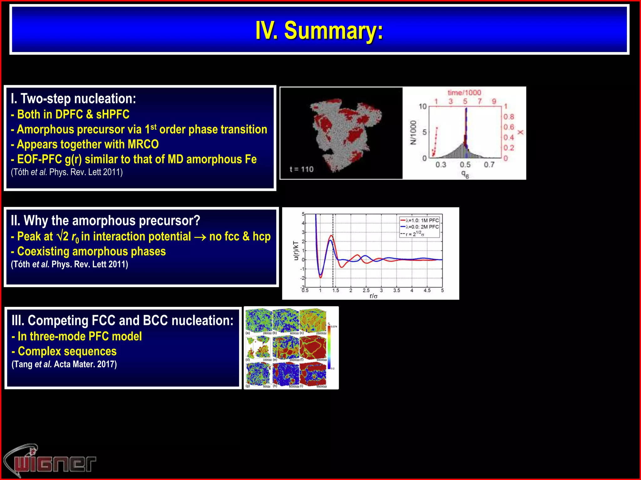
Tóth et al. PRL (2011).
Red (bcc-like) if
q4 [0.02, 0.07]
q6 [0.48, 0.52]
Steinhardt, Nelson, Ronchetti, PRB (1983)
Starts to solidify as amorphous,
then crystallizes ! A’la 2D & 3D colloids.
Instantaneous quench in DPFC: 22](https://image.slidesharecdn.com/nucleationiiichimads-181009173606/75/Nucleation-III-Phase-field-crystal-modeling-of-nucleation-process-25-2048.jpg)
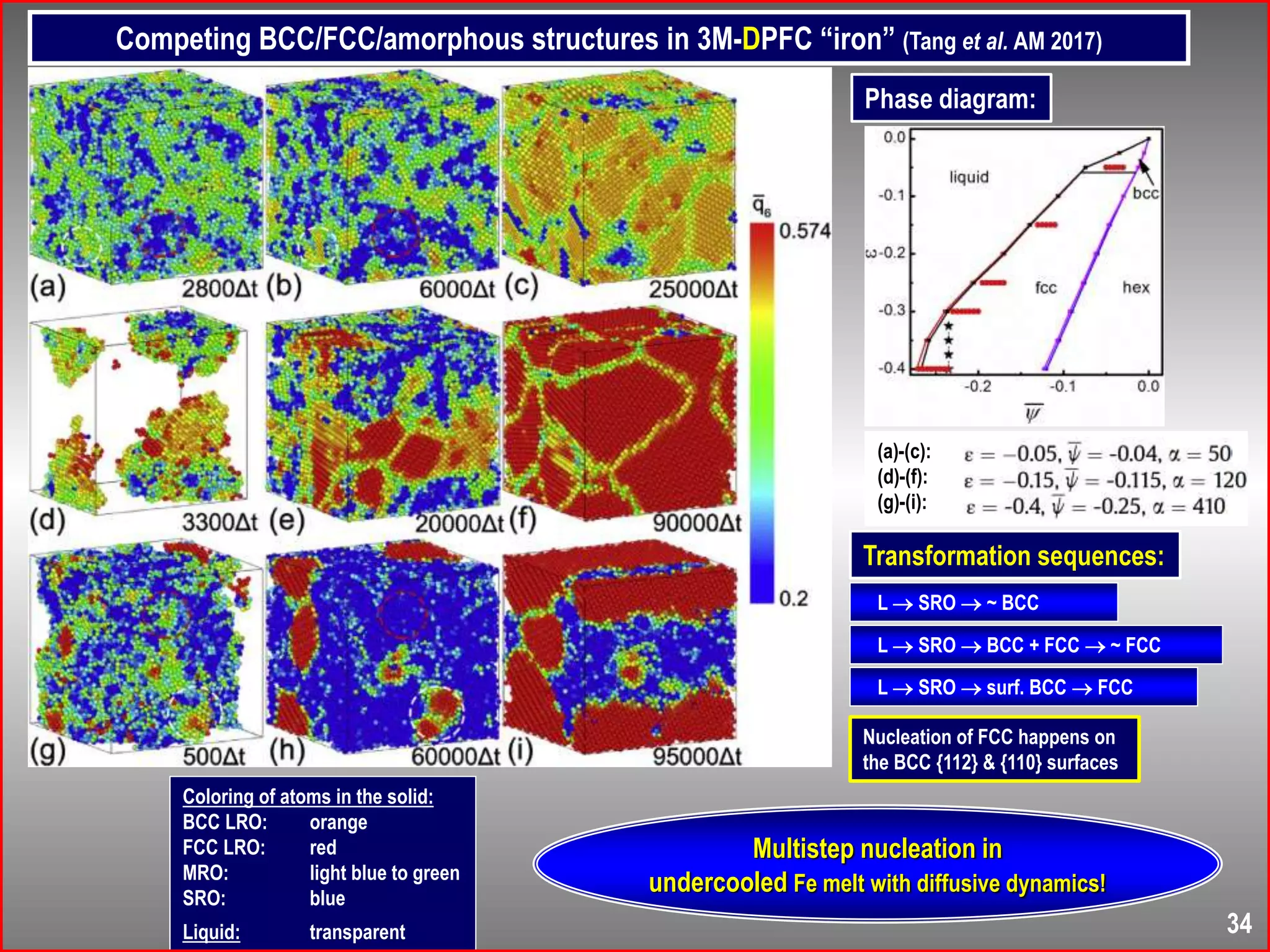
![Lechner & Dellago, JCP (2008)
qi of Lechner & Dellago
Black: bcc
Yellow: Icosah.
Green: hcp
Red: fcc
Structural aspects:
Greenq6 > 0.4
Redq6 [0.28, 0.4]
Whiteq6 < 0.28
Red (bcc-like) if
q4 [0.02, 0.07]
q6 [0.48, 0.52]
Observations:
- Am. precursor is structurally like LJ liquid
- MRCO and amorphous domains appear parallel
- Heterogeneous-like bcc nucleation on am. domains
- Literature: LJ, HS, colloids, now PFC. What else?
Kawasaki & Tanaka, PNAS (2010)
MRCO (Brownian Dynamics)
24](https://image.slidesharecdn.com/nucleationiiichimads-181009173606/75/Nucleation-III-Phase-field-crystal-modeling-of-nucleation-process-27-2048.jpg)

![Potential from g(r):
Schommers’ iterative method
- initial guess (potential of mean force)
- MC 4096 particle g(r)
correction to u(r):
f kT log[gPFC(r)/gsim(r)]
(repeat these steps until convergence)
(Efficient and accurate for one component
fluids, Schommers PRA 1983)
Work done with Gergely Tóth,
Eötvös University, Inst. of Chemistry
Budapest, Hungary
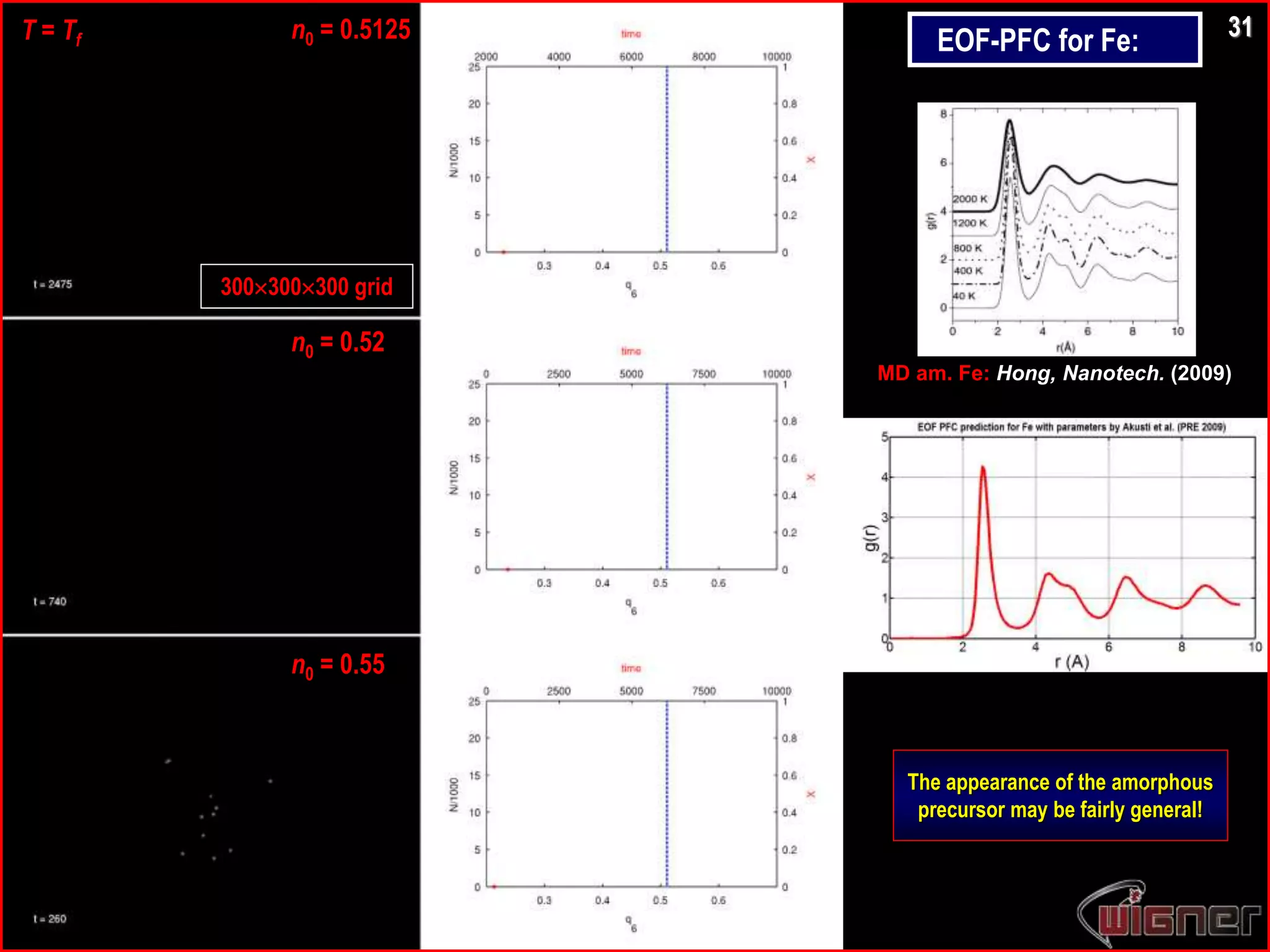
Amorphous structure & eff. pair potential vs. :
PFC models:
Molecular Dynamics:
Am. Fe: Hong,
Nanotech. (2009)
Am. Ni: Yu et al.,
TNMSC (2006)
Like Dzugutov’s potential for
monatomic model glass former:
Peak at ~ 2 rmin
(suppresses fcc, hcp & sc crystals)
Why amorphous precursor?
30
Summarizing the results for LJ, HS, & PFC potentials:
(see Tóth at al. PRL 2011)
- Repulsive core suffices for an amorphous precursor;
- Peak at ~ 2 rmin appears to suppress fcc & hcp;
- Multiple minima coexisting disordered phases;
(a’la Mishima & Stanley, Nature 1998)](https://image.slidesharecdn.com/nucleationiiichimads-181009173606/75/Nucleation-III-Phase-field-crystal-modeling-of-nucleation-process-33-2048.jpg)