This document provides guidance on designing environments using VMware NSX-T. It discusses NSX-T's architecture components including the management plane, control plane, and data plane. It describes NSX-T's value in supporting heterogeneous environments across hypervisors, containers, clouds, and endpoints. The document is intended to help architects design NSX-T deployments and covers topics such as logical switching, routing, security, load balancing, and performance optimization. Design recommendations are provided for various deployment scenarios.


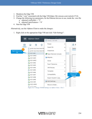
![VMware NSX-T Reference Design Guide
241
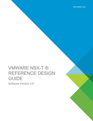
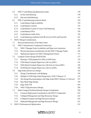
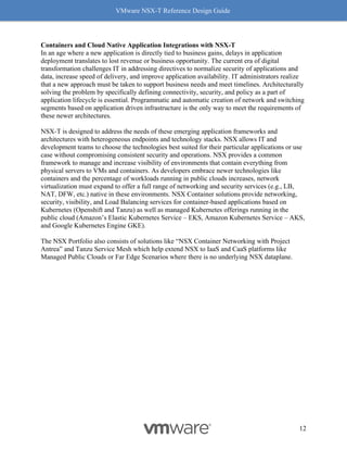
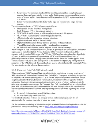
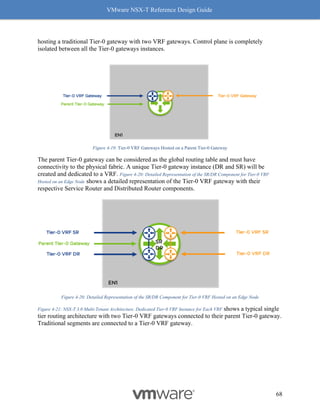
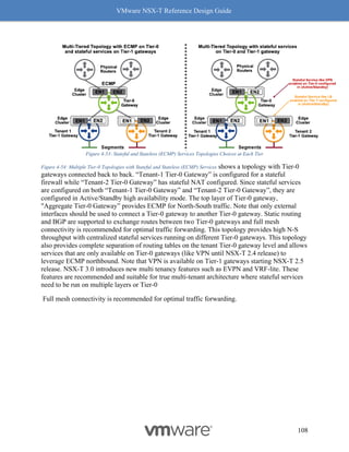
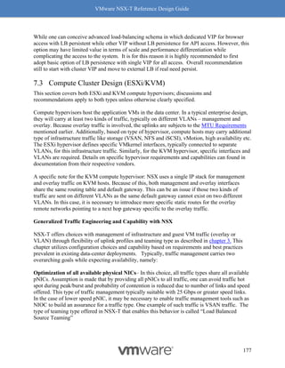
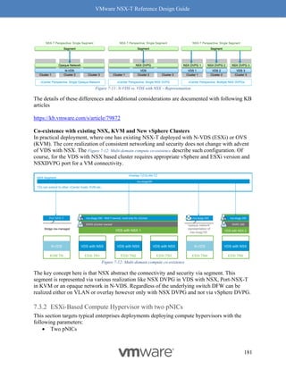
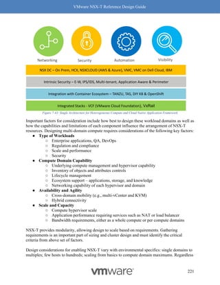
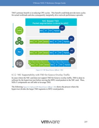
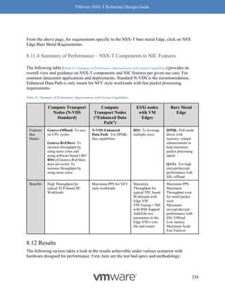
4. Click on the [+] symbol to expand and check the features supported.
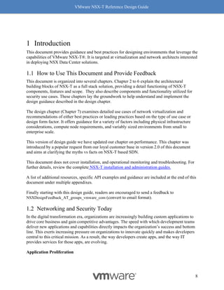
Figure 8-8: Steps to Verify Compatibility - Part 3
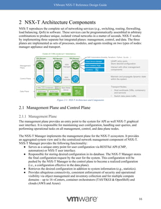
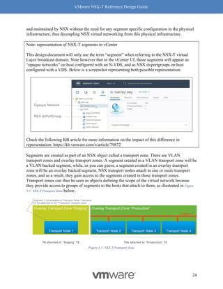
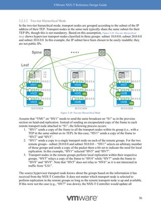
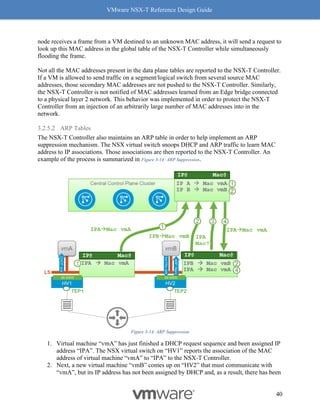
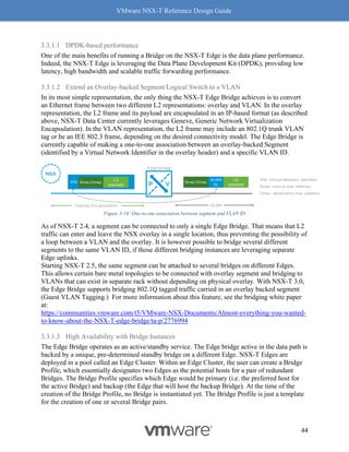
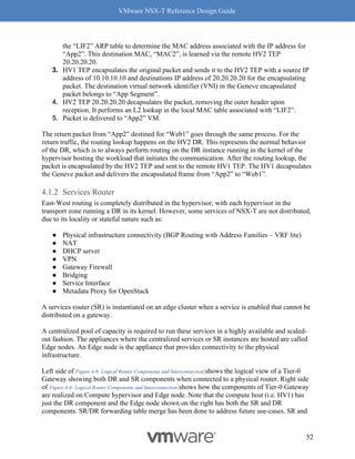
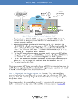
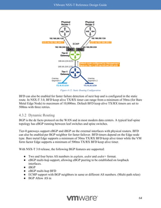
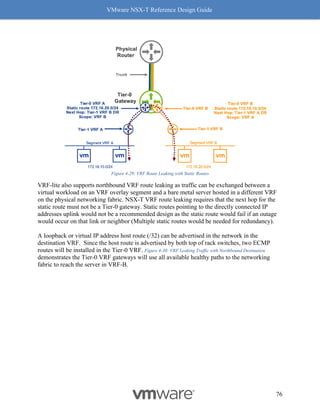
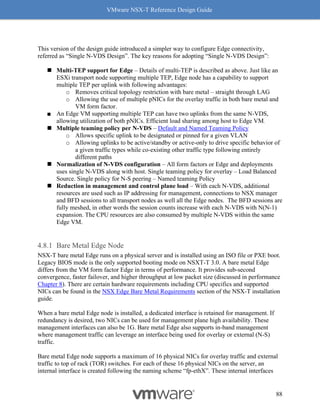
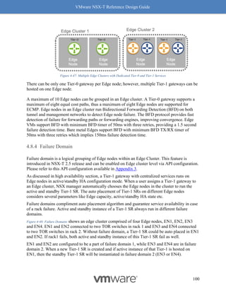
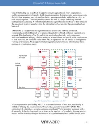
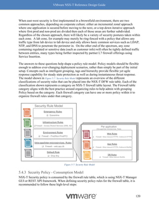
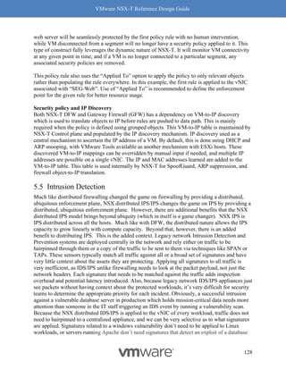
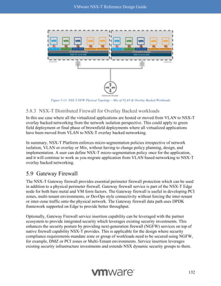
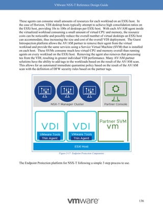
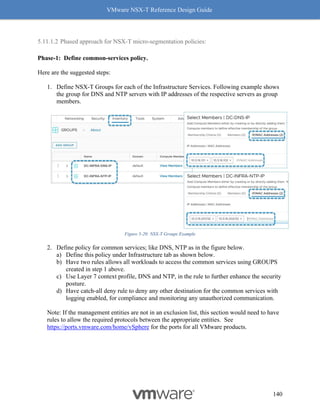
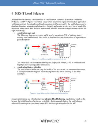
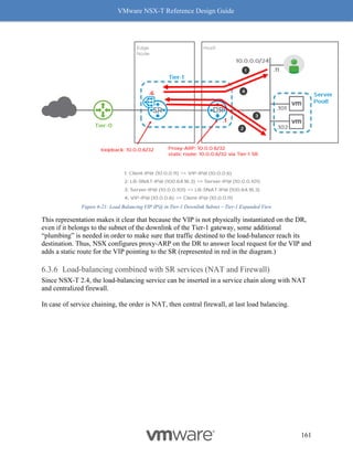
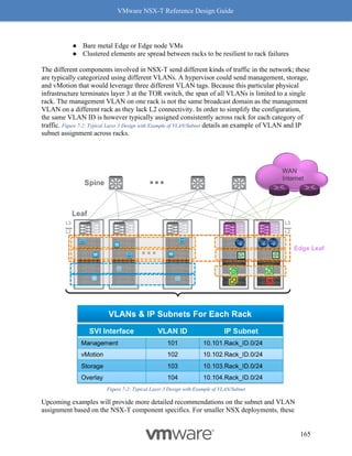
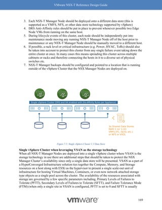
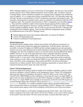
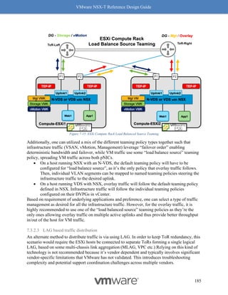
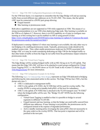
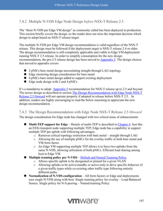
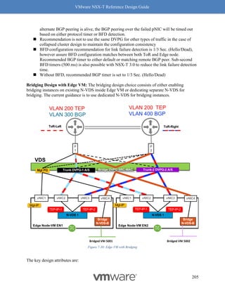
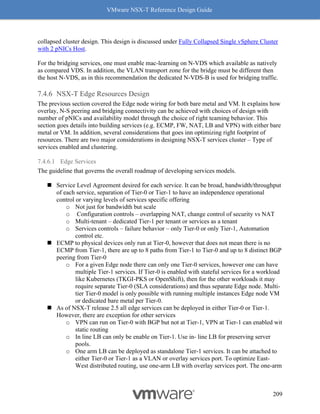
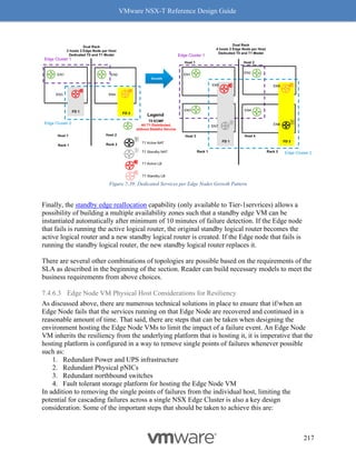
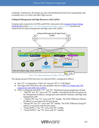
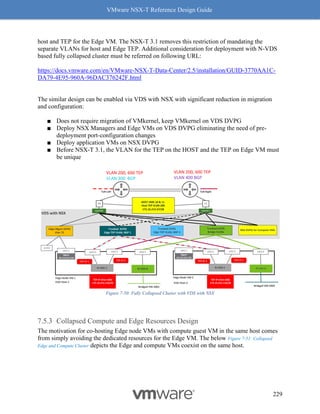
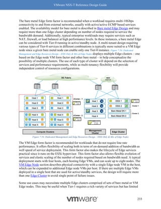
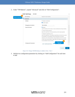
5. Make sure the concerned driver actually has the “Geneve-Offload and Geneve-Rx
Filters” as listed features.
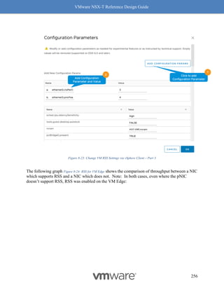
Figure 8-9: Steps to Verify Compatibility - Part 4
Follow the above procedure to ensure Geneve offload and Geneve Rx Filters are available on
any NIC card you are planning to deploy for use with NSX-T. As mentioned earlier, not having
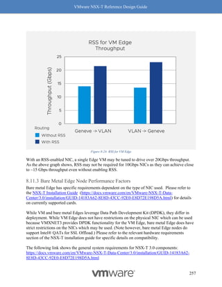
Geneve offload will impact performance with higher CPU cycles spent to make up for the lack of
software based Geneve offload capabilities.
ESXi-Based Hypervisor](https://image.slidesharecdn.com/nsx-treferencedesignguide3-0-211223070607/85/Nsx-t-reference-design-guide-3-0-242-320.jpg)
![VMware NSX-T Reference Design Guide
242
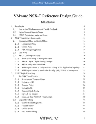
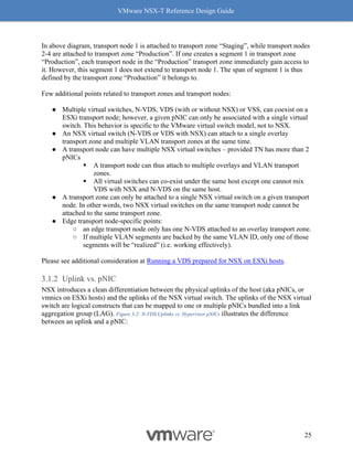
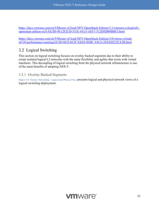
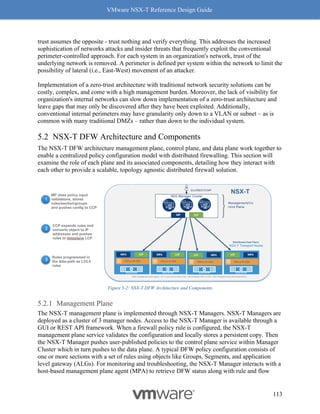
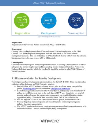
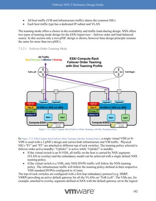
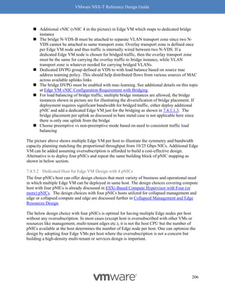
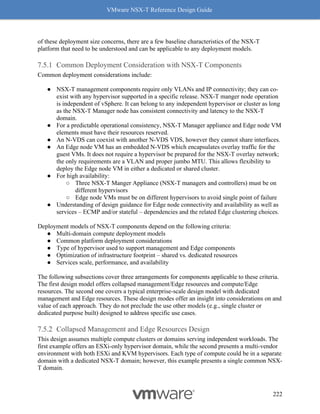
On an ESXi host with a NIC card supporting Geneve-Offload in Hardware with the appropriate
supported driver, the following commands can be used to confirm Geneve-Offload is enabled on
a pNIC – in this case pNIC vmnic3:
[Host-1] vsish -e get /net/pNics/vmnic3/properties | grep
".*Activated.*Geneve"
Device Hardware Cap Activated:: 0x793c032b ->
VMNET_CAP_SG VMNET_CAP_IP4_CSUM VMNET_CAP_HIGH_DMA
VMNET_CAP_TSO VMNET_CAP_HW_TX_VLAN VMNET_CAP_HW_RX_VLAN
VMNET_CAP_SG_SPAN_PAGES VMNET_CAP_IP6_CSUM VMNET_CAP_TSO6
VMNET_CAP_TSO256k VMNET_CAP_ENCAP VMNET_CAP_Geneve_OFFLOAD
VMNET_CAP_IP6_CSUM_EXT_HDRS VMNET_CAP_TSO6_EXT_HDRS
VMNET_CAP_SCHED
CLI 1 Check Geneve Offload Support
Look for the tag “VMNET_CAP_Geneve_OFFLOAD”, highlighted in red above. This verbiage
indicates the Geneve Offload is activated on NIC card vmnic3. If the tag is missing, then it
means Geneve Offload is not enabled because either the NIC or its driver does not support it.
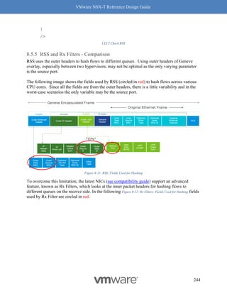
Receive Side Scaling (RSS) and Rx Filters
Readers familiar with software based VxLAN deployment with NSX-V, are likely familiar with
the immense performance benefits of RSS, including improving the performance of overlay
traffic by four (4) times.
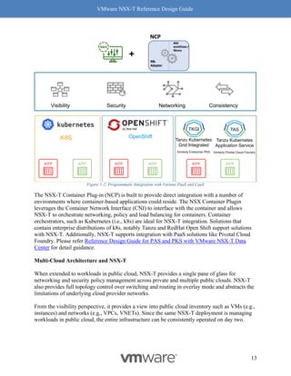
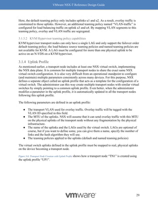
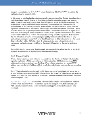
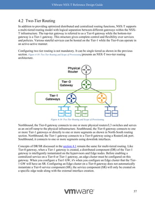
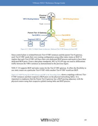
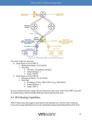
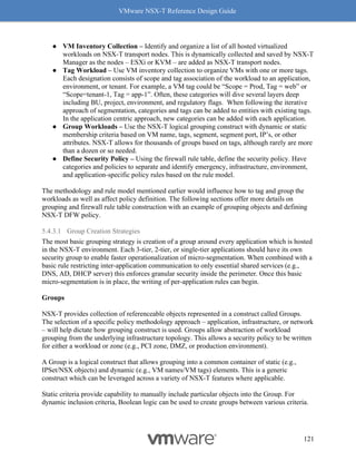
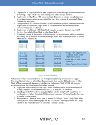
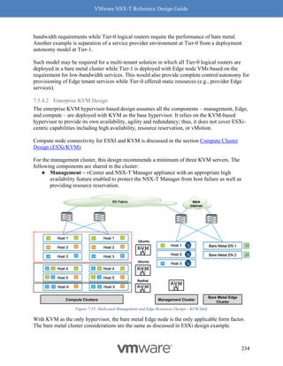
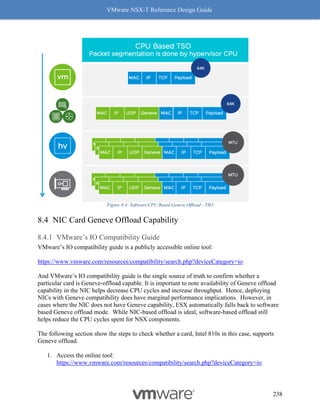
Benefits with RSS
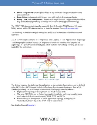
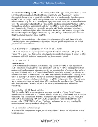
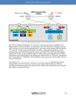
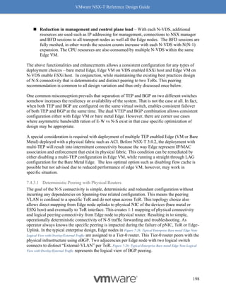
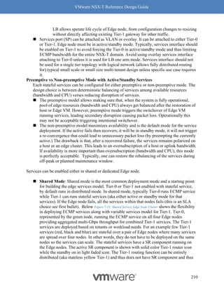
RSS, another long-standing TCP enhancement, enables use of multiple cores on the receive side
to process incoming traffic. Without RSS, ESX by default will use only one core to process
incoming traffic. Utilizing only one core has a huge impact on the overall throughput as the
receiving node then becomes the bottleneck. RSS on the NIC creates multiple queues to process
incoming traffic and efficiently uses a core for each queue, with most NIC cards being able to
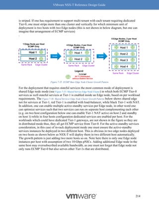
support at least 4 queues. Hence the 4x benefit of using RSS. See Figure 8-10: RSS for a visual
representation of how this works.
RSS for overlay
While RSS itself in general is in fairly common use today, there are NICs which still may not
support RSS for overlay. Hence, our recommendation is to confirm with the NIC vendor whether
RSS for overlay traffic is available in hardware, then also confirm with the VMware
Compatibility IO Guide
(https://www.vmware.com/resources/compatibility/search.php?deviceCategory=io) whether
there is a RSS-certified driver.](https://image.slidesharecdn.com/nsx-treferencedesignguide3-0-211223070607/85/Nsx-t-reference-design-guide-3-0-243-320.jpg)
![VMware NSX-T Reference Design Guide
243
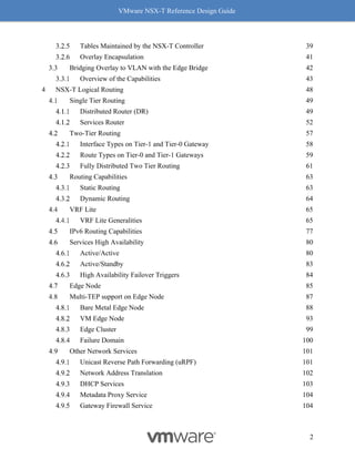
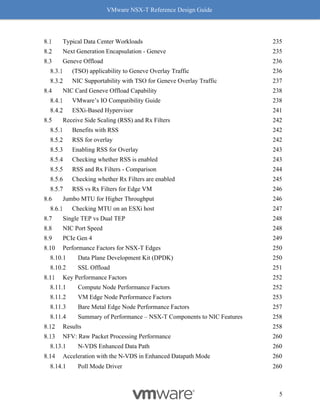
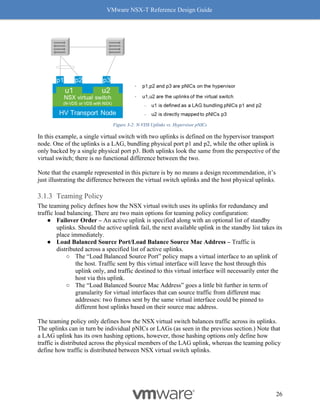
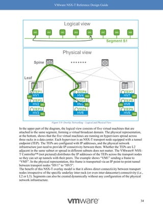
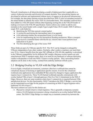
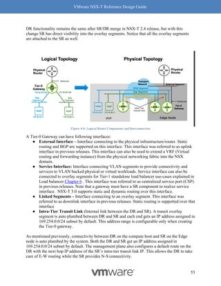
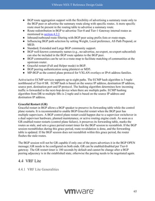
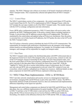
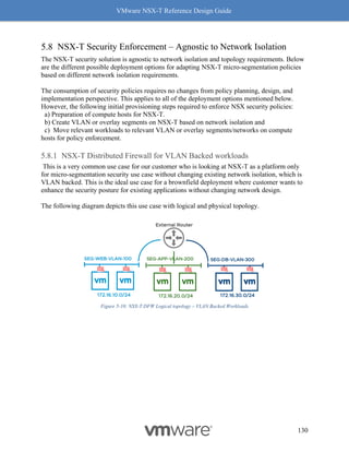
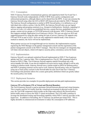
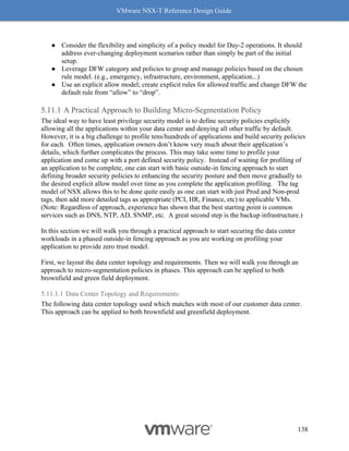
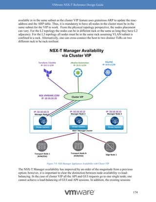
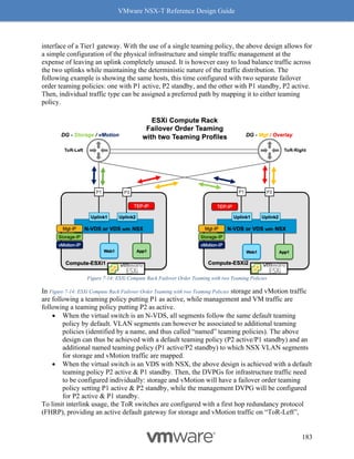
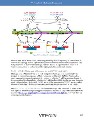
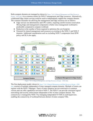
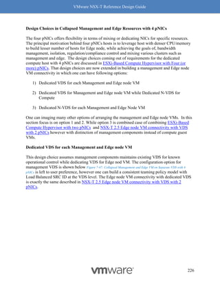
Figure 8-10: RSS
Enabling RSS for Overlay
Every vendor has their own unique mechanism to enable RSS for overlay traffic. There are also
cases where the setting used to change RSS is different based on the driver version. Please refer
to the concerned vendor documentation for details on enabling RSS for specific NICs.
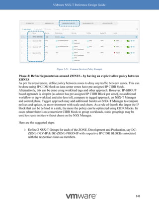
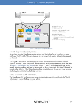
Checking whether RSS is enabled
Use the “vsish” command to check whether RSS is enabled. The following example shows how
to check whether RSS (marked blue) is enabled on NIC vmnic (marked in red).
[Host-1] # vsish
/> get /net/pNics/vmnic0/rxqueues/info
rx queues info {
# queues supported:5
# filters supported:126
# active filters:0
Rx Queue features:features: 0x1a0 -> Dynamic RSS Dynamic
Preemptible](https://image.slidesharecdn.com/nsx-treferencedesignguide3-0-211223070607/85/Nsx-t-reference-design-guide-3-0-244-320.jpg)
![VMware NSX-T Reference Design Guide
245
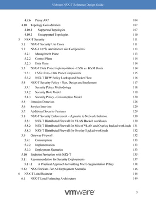
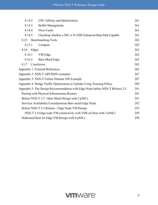
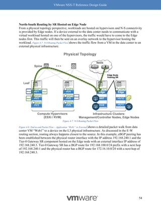
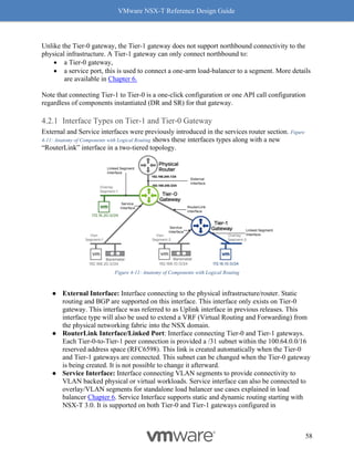
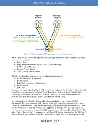
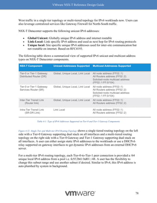
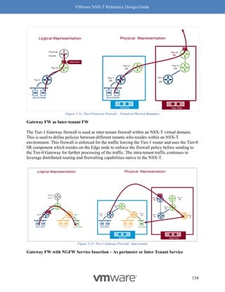
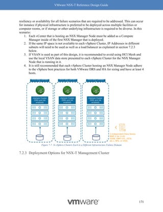
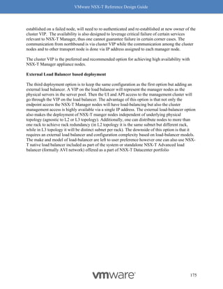
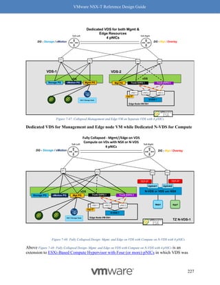
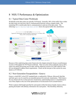
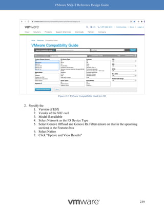
Figure 8-12: Rx Filters: Fields Used for Hashing
Simply put, Rx Filters look at the inner packet headers for queuing decisions. As driven by
NSX, the queuing decision itself is based on flows and bandwidth utilization. Hence, Rx Filters
provide optimal queuing compared to RSS, which is akin to a hardware-based brute force
method.
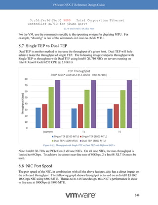
Checking whether Rx Filters are enabled
Rx Filters are enabled by default on a NIC that supports Rx Filters in hardware and has a driver
to use it. Please use the VMware’s Compatibility Guide for IO, discussed earlier in this chapter,
to confirm whether Rx Filters are available. In VCG for I/O page, select “Geneve-RxFilter”, and
make sure the right driver is installed on the ESXi host.
On the ESXi host, use the “vsish” command to check whether Rx Filters are enabled. The
following example shows how to check whether the NIC vmnic5 (marked in red) has Rx Filters
Enabled for Geneve (marked in blue)
Check Whether Rx / Tx Filters are Enabled:
[Host-1] vsish
/> cat /net/pNics/vmnic5/rxqueues/info
rx queues info {
# queues supported:8
# filters supported:512
# active filters:0
# filters moved by load balancer:254
# of Geneve OAM filters:2
RX filter classes:Rx filter class: 0x1c -> VLAN_MAC
VXLAN Geneve GenericEncap](https://image.slidesharecdn.com/nsx-treferencedesignguide3-0-211223070607/85/Nsx-t-reference-design-guide-3-0-246-320.jpg)
![VMware NSX-T Reference Design Guide
247
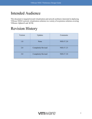
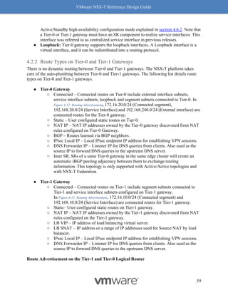
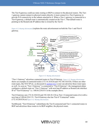
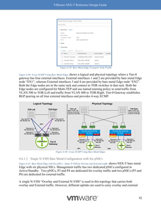
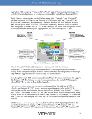
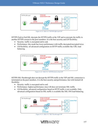
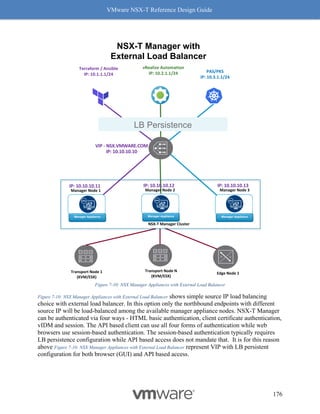
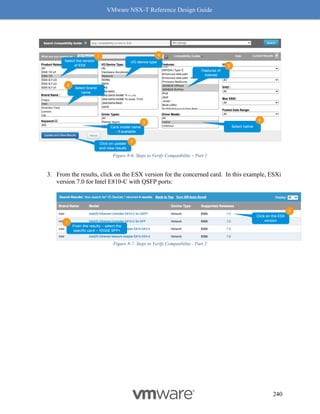
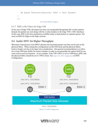
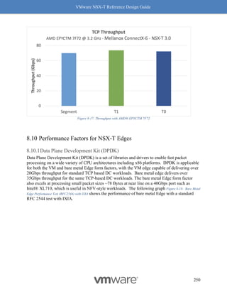
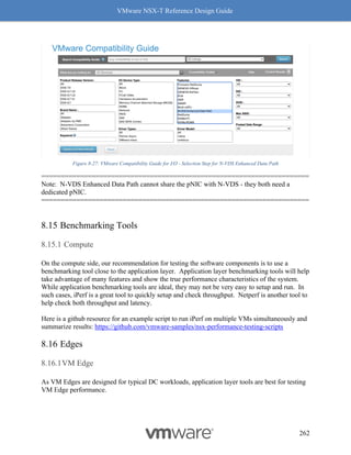
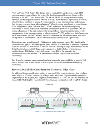
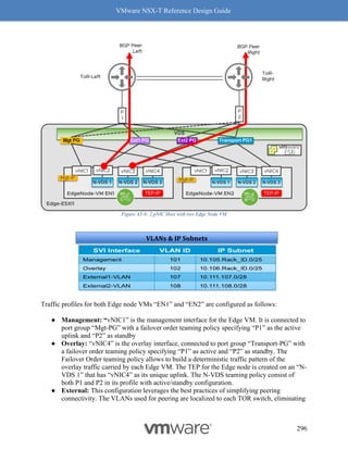
Why should you care about MTU values? MTU is a key factor for driving high throughput, and
this is true for any NIC which supports 9K MTU also known as jumbo frame. The following
graph Figure 8-14: MTU and Throughput shows throughput achieved with MTU set to 1500 and 8800:
Figure 8-14: MTU and Throughput
Our recommendation for optimal throughput is to set the underlying fabric and ESX host’s
pNICs to 9000 and the VM vNIC MTU to 8800.
Notes for Figure 8-14: MTU and Throughput:
• The above graph represents a single pair of VMs running iPerf with 4 sessions.
• For both VM MTU cases of 1500 and 8800, the MTU on the host was 9000 with
demonstrated performance improvements.
Checking MTU on an ESXi host
Use the esxcfg-nics command to check the MTU:
[Host-1] esxcfg-nics -l | grep vmnic5
vmnic5 0000:84:00.0 i40en Up 40000Mbps Full](https://image.slidesharecdn.com/nsx-treferencedesignguide3-0-211223070607/85/Nsx-t-reference-design-guide-3-0-248-320.jpg)
![VMware NSX-T Reference Design Guide
268
"Tier1": {
"resource_type": "Tier1",
"id": "DEV-tier-1-gw",
"description": "DEV-tier-1-gw",
"display_name": "DEV-tier-1-gw",
"failover_mode": "NON_PREEMPTIVE",
"tier0_path":"/infra/tier-0s/DC-01-ENVT-01-TIER-0-GW",
"route_advertisement_types": [
"TIER1_CONNECTED",
"TIER1_STATIC_ROUTES"
],
"children": [
{
"resource_type":"ChildLocaleServices",
"LocaleServices":{
"resource_type":"LocaleServices",
"id": "default",
"edge_cluster_path": "/infra/sites/default/enforcement-points/default/edge-
clusters/e6d88327-640b-4d33-b0b5-578b1311e7b0"
}
},
{
"resource_type": "ChildSegment",
"Segment": {
"resource_type": "Segment",
"id": "DEV-RED-web-segment",
"description": "DEV-RED-web-segment",
"display_name": "DEV-RED-web-segment",
"transport_zone_path": "/infra/sites/default/enforcement-points/default/transport-
zones/3a60b876-b912-400d-91b2-bdb0ef602fa0",
"subnets": [
{
"gateway_address": "10.10.1.1/24"
}
]
}
},
{
"resource_type": "ChildSegment",
"Segment": {
"resource_type": "Segment",
"id": "DEV-RED-app-segment",
"description": "DEV-RED-app-segment",
"display_name": "DEV-RED-app-segment",](https://image.slidesharecdn.com/nsx-treferencedesignguide3-0-211223070607/85/Nsx-t-reference-design-guide-3-0-269-320.jpg)
![VMware NSX-T Reference Design Guide
269
"transport_zone_path": "/infra/sites/default/enforcement-points/default/transport-
zones/3a60b876-b912-400d-91b2-bdb0ef602fa0",
"subnets": [
{
"gateway_address": "10.20.2.1/24"
}
]
}
},
{
"resource_type": "ChildSegment",
"Segment": {
"resource_type": "Segment",
"id": "DEV-RED-db-segment",
"description": "DEV-RED-db-segment",
"display_name": "DEV-RED-db-segment",
"transport_zone_path": "/infra/sites/default/enforcement-points/default/transport-
zones/3a60b876-b912-400d-91b2-bdb0ef602fa0",
"subnets": [
{
"gateway_address": "10.20.3.1/24"
}
]
}
},
{
"resource_type": "ChildPolicyNat",
"PolicyNat": {
"id": "USER",
"resource_type": "PolicyNat",
"children": [
{
"resource_type": "ChildPolicyNatRule",
"PolicyNatRule": {
"resource_type": "PolicyNatRule",
"id": "DEV-RED-nat-rule-1",
"action": "SNAT",
"source_network": "10.10.0.0/23",
"service": "",
"translated_network": "30.30.30.20",
"scope": [],
"enabled": true,
"firewall_match": "BYPASS",
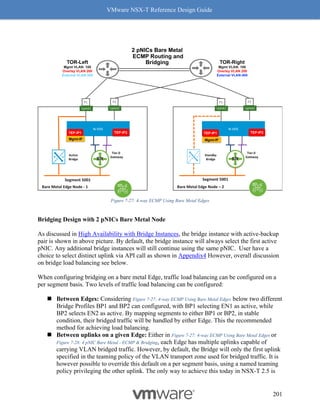
"display_name": "DEV-RED-nat-rule-1",
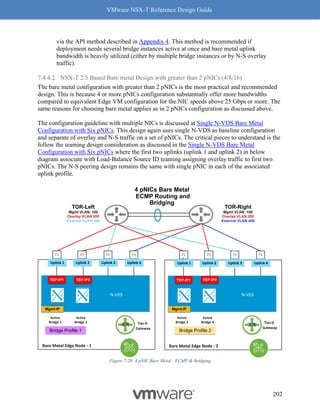
"parent_path": "/infra/tier-1s/DEV-tier-1-gw/nat/USER"
}](https://image.slidesharecdn.com/nsx-treferencedesignguide3-0-211223070607/85/Nsx-t-reference-design-guide-3-0-270-320.jpg)
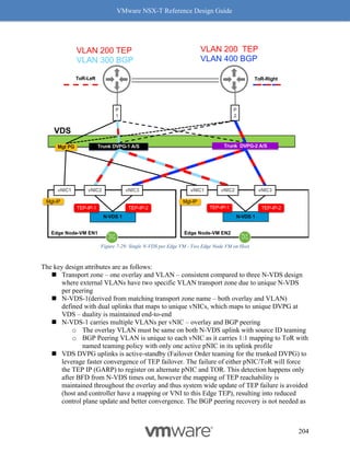
![VMware NSX-T Reference Design Guide
270
}
]
}
}
]
}
},
{
"resource_type": "ChildDomain",
"marked_for_delete": false,
"Domain": {
"id": "default",
"resource_type": "Domain",
"description": "default",
"display_name": "default",
"marked_for_delete": false,
"children": [
{
"resource_type": "ChildGroup",
"Group": {
"resource_type": "Group",
"marked_for_delete": false,
"description": "DEV-RED-web-vms",
"display_name": "DEV-RED-web-vms",
"id": "DEV-RED-web-vms",
"expression": [
{
"member_type": "VirtualMachine",
"value": "DEVREDwebvm",
"key": "Tag",
"operator": "EQUALS",
"resource_type": "Condition"
}
]
}
},
{
"resource_type": "ChildGroup",
"Group": {
"resource_type": "Group",
"marked_for_delete": false,
"description": "DEV-RED-app-vms",
"display_name": "DEV-RED-app-vms",
"id": "DEV-RED-app-vms",
"expression": [
{](https://image.slidesharecdn.com/nsx-treferencedesignguide3-0-211223070607/85/Nsx-t-reference-design-guide-3-0-271-320.jpg)
![VMware NSX-T Reference Design Guide
271
"member_type": "VirtualMachine",
"value": "DEVREDappvm",
"key": "Tag",
"operator": "EQUALS",
"resource_type": "Condition"
}
]
}
},
{
"resource_type": "ChildGroup",
"Group": {
"resource_type": "Group",
"description": "DEV-RED-db-vms",
"display_name": "DEV-RED-db-vms",
"id": "DEV-RED-db-vms",
"expression": [
{
"member_type": "VirtualMachine",
"value": "DEVREDdbvm",
"key": "Tag",
"operator": "EQUALS",
"resource_type": "Condition"
}
]
}
},
{
"resource_type": "ChildSecurityPolicy",
"marked_for_delete": false,
"SecurityPolicy": {
"id": "DEV-RED-intra-app-policy",
"resource_type": "SecurityPolicy",
"description": "communication map",
"display_name": "DEV-RED-intra-app-policy",
"rules": [
{
"resource_type": "Rule",
"description": "Communication Entry",
"display_name": "any-to-DEV-RED-web",
"sequence_number": 1,
"source_groups": [
"ANY"
],
"destination_groups": [
"/infra/domains/default/groups/DEV-RED-web-vms"](https://image.slidesharecdn.com/nsx-treferencedesignguide3-0-211223070607/85/Nsx-t-reference-design-guide-3-0-272-320.jpg)
![VMware NSX-T Reference Design Guide
272
],
"services": [
"/infra/services/HTTPS"
],
"action": "ALLOW"
},
{
"resource_type": "Rule",
"description": "Communication Entry 2",
"display_name": "DEV-RED-web-to-app",
"sequence_number": 2,
"source_groups": [
"/infra/domains/default/groups/DEV-RED-web-vms"
],
"destination_groups": [
"/infra/domains/default/groups/DEV-RED-app-vms"
],
"services": [
"/infra/services/HTTP"
],
"action": "ALLOW"
},
{
"resource_type": "Rule",
"description": "Communication Entry 3",
"display_name": "DEV-RED-app-to-db",
"sequence_number": 2,
"source_groups": [
"/infra/domains/default/groups/DEV-RED-app-vms"
],
"destination_groups": [
"/infra/domains/default/groups/DEV-RED-db-vms"
],
"services": [
"/infra/services/MySQL"
],
"action": "ALLOW"
}
]
}
},
{
"resource_type": "ChildGatewayPolicy",
"marked_for_delete": false,
"GatewayPolicy": {
"resource_type": "GatewayPolicy",](https://image.slidesharecdn.com/nsx-treferencedesignguide3-0-211223070607/85/Nsx-t-reference-design-guide-3-0-273-320.jpg)
![VMware NSX-T Reference Design Guide
273
"id": "DEV-RED-section",
"display_name": "DEV-RED-section",
"parent_path": "/infra/domains/default",
"marked_for_delete": false,
"rules": [
{
"source_groups": [
"ANY"
],
"destination_groups": [
"/infra/domains/default/groups/DEV-RED-web-vms"
],
"services": [
"/infra/services/HTTPS"
],
"profiles": [
"ANY"
],
"action": "ALLOW",
"logged": false,
"scope": [
"/infra/tier-1s/DEV-tier-1-gw"
],
"disabled": false,
"notes": "",
"direction": "IN_OUT",
"tag": "",
"ip_protocol": "IPV4_IPV6",
"resource_type": "Rule",
"id": "Any-to-web",
"display_name": "Any-to-web"
},
{
"source_groups": [
"ANY"
],
"destination_groups": [
"/infra/domains/default/groups/DEV-RED-web-vms",
"/infra/domains/default/groups/DEV-RED-app-vms",
"/infra/domains/default/groups/DEV-RED-db-vms"
],
"services": [
"ANY"
],
"profiles": [
"ANY"](https://image.slidesharecdn.com/nsx-treferencedesignguide3-0-211223070607/85/Nsx-t-reference-design-guide-3-0-274-320.jpg)
![VMware NSX-T Reference Design Guide
274
],
"action": "DROP",
"logged": false,
"scope": [
"/infra/tier-1s/DEV-tier-1-gw"
],
"disabled": false,
"notes": "",
"direction": "IN_OUT",
"tag": "",
"ip_protocol": "IPV4_IPV6",
"resource_type": "Rule",
"id": "DenyAny",
"display_name": "DenyAny"
}
]
}
}
]
}
},
{
"resource_type": "ChildLBClientSslProfile",
"marked_for_delete": false,
"LBClientSslProfile": {
"resource_type": "LBClientSslProfile",
"id": "batchSetupClientSslProfile",
"cipher_group_label": "CUSTOM",
"session_cache_enabled": true,
"ciphers": [
"TLS_ECDHE_RSA_WITH_AES_128_GCM_SHA256",
"TLS_ECDHE_RSA_WITH_AES_256_GCM_SHA384"
],
"protocols": [
"TLS_V1_2"
]
}
},
{
"resource_type": "ChildLBServerSslProfile",
"marked_for_delete": false,
"LBServerSslProfile": {
"resource_type": "LBServerSslProfile",
"id": "batchSetupServerSslProfile",
"cipher_group_label": "CUSTOM",
"session_cache_enabled": true,](https://image.slidesharecdn.com/nsx-treferencedesignguide3-0-211223070607/85/Nsx-t-reference-design-guide-3-0-275-320.jpg)
![VMware NSX-T Reference Design Guide
275
"ciphers": [
"TLS_ECDHE_RSA_WITH_AES_128_GCM_SHA256",
"TLS_ECDHE_RSA_WITH_AES_256_GCM_SHA384"
],
"protocols": [
"TLS_V1_2"
]
}
},
{
"resource_type": "ChildLBAppProfile",
"marked_for_delete": false,
"LBAppProfile": {
"resource_type": "LBHttpProfile",
"id": "batchSetupHttpAppProfile",
"x_forwarded_for": "INSERT"
}
},
{
"resource_type": "ChildLBMonitorProfile",
"marked_for_delete": false,
"LBMonitorProfile": {
"resource_type": "LBHttpMonitorProfile",
"marked_for_delete": false,
"id": "batchSetupHttpMonitor1",
"monitor_port": 80,
"timeout": 5,
"response_status_codes": [
200,
300
]
}
},
{
"resource_type": "ChildLBMonitorProfile",
"marked_for_delete": false,
"LBMonitorProfile": {
"resource_type": "LBHttpsMonitorProfile",
"id": "batchSetupHttpsMonitor1",
"monitor_port": 443,
"timeout": 5,
"response_status_codes": [
200
]
}
},](https://image.slidesharecdn.com/nsx-treferencedesignguide3-0-211223070607/85/Nsx-t-reference-design-guide-3-0-276-320.jpg)
![VMware NSX-T Reference Design Guide
276
{
"resource_type": "ChildLBService",
"marked_for_delete": false,
"LBService": {
"resource_type": "LBService",
"id": "DEV-RED-LbService",
"connectivity_path": "/infra/tier-1s/DEV-tier-1-gw",
"error_log_level": "DEBUG",
"access_log_enabled": true
}
},
{
"resource_type": "ChildLBVirtualServer",
"marked_for_delete": false,
"LBVirtualServer": {
"resource_type": "LBVirtualServer",
"id": "DEV-RED-VirtualServer1",
"lb_service_path": "/infra/lb-services/DEV-RED-LbService",
"ip_address": "30.10.200.1",
"ports": [
"443"
],
"pool_path": "/infra/lb-pools/DEV-RED-web-Pool",
"application_profile_path": "/infra/lb-app-profiles/batchSetupHttpAppProfile",
"client_ssl_profile_binding": {
"ssl_profile_path": "/infra/lb-client-ssl-profiles/batchSetupClientSslProfile",
"default_certificate_path": "/infra/certificates/batchSslSignedCertDEV-RED",
"client_auth_ca_paths": [
"/infra/certificates/batchSslCACertDEV-RED"
],
"certificate_chain_depth": 2
},
"server_ssl_profile_binding": {
"ssl_profile_path": "/infra/lb-server-ssl-profiles/batchSetupServerSslProfile",
"server_auth": "IGNORE",
"client_certificate_path": "/infra/certificates/batchSslSignedCertDEV-RED",
"server_auth_ca_paths": [
"/infra/certificates/batchSslCACertDEV-RED"
],
"certificate_chain_depth": 2
}
}
},
{
"resource_type": "ChildLBPool",
"marked_for_delete": false,](https://image.slidesharecdn.com/nsx-treferencedesignguide3-0-211223070607/85/Nsx-t-reference-design-guide-3-0-277-320.jpg)
![VMware NSX-T Reference Design Guide
277
"LBPool": {
"id": "DEV-RED-web-Pool",
"resource_type": "LBPool",
"marked_for_delete": false,
"active_monitor_paths": [
"/infra/lb-monitor-profiles/batchSetupHttpsMonitor1"
],
"algorithm": "ROUND_ROBIN",
"member_group": {
"group_path": "/infra/domains/default/groups/DEV-RED-web-vms",
"ip_revision_filter": "IPV4"
},
"snat_translation": {
"type": "LBSnatDisabled"
}
}
},
{
"resource_type": "ChildLBVirtualServer",
"marked_for_delete": false,
"LBVirtualServer": {
"resource_type": "LBVirtualServer",
"id": "DEV-RED-VirtualServer2",
"lb_service_path": "/infra/lb-services/DEV-RED-LbService",
"ip_address": "10.10.200.1",
"ports": [
"80"
],
"pool_path": "/infra/lb-pools/DEV-RED-app-Pool",
"application_profile_path": "/infra/lb-app-profiles/batchSetupHttpAppProfile"
}
},
{
"resource_type": "ChildLBPool",
"marked_for_delete": false,
"LBPool": {
"id": "DEV-RED-app-Pool",
"resource_type": "LBPool",
"marked_for_delete": false,
"active_monitor_paths": [
"/infra/lb-monitor-profiles/batchSetupHttpMonitor1"
],
"algorithm": "ROUND_ROBIN",
"member_group": {
"group_path": "/infra/domains/default/groups/DEV-RED-app-vms",
"ip_revision_filter": "IPV4"](https://image.slidesharecdn.com/nsx-treferencedesignguide3-0-211223070607/85/Nsx-t-reference-design-guide-3-0-278-320.jpg)
![VMware NSX-T Reference Design Guide
280
B5eCud4vOLY1iLyEt2CnmTCPH9No1lk2B/n1Ej/QJOPFJC/wbDeTiTg7sgJIdTHcRMdumIM
htQHTYYXxd3u3Oy7M9fxYCnHQE14nejh4/37Qn1bylOqACVT0u++pamlT1fc70Y1Bwq5xS
/OJGRmK0FAHiWus/3QvV9KjnUucCAwEAAaNdMFswHQYDVR0OBBYEFOqoDj0V7pC6
BhIjy3sVV73EfBZMMB8GA1UdnIwQYMBaAFOqoDj0V7pC6BhIjy3sVV73EfBZMMAwG
A1UdEwQFMAMBAf8wCwYDVR0PnBAQDAgEGMA0GCSqGSIb3DQEBBQUAA4ICAQ
CFD6o1SALwTxAMmHqt6rrwjZdrUMLen0vZ1lsjlr82MrUk9L1YOsSFRFGLpYMhmIC/pdaz
iMxEOI+RifRSI9sk/sY3XlsrLnuI/92sE9qLV6/PGZsaHYeQcDduaqLqHj7LnsCkgoVZqYhpgp
RvgiuUm8faWW9piGnO0t/PuKpyxWRn+0dqzsH+Nhr/lMoYPqeURphphqiiqoTGcmREEYrD
C+MoUsTeHy4nPy2NNCB5J5qQpMfwfWBeLf0dXXpFk7ggF0dHW/Ma/b8g+fdVE6AswY3
NG6TV8phynOoNCgqIIO18OuFVL2DnYDoDaEjin/Y5l6U32BAsiCTyiUrCr4+4V7Awa10ipZ
iPKniQlIs0vbXD9tSyiP1yTn3tXXHE7OZnT5nE1//UQbEaQWbQcgZOCoH54M7m03aMS5n
1PHs9BHt7zj3ASDF682rsiZTKgW+hv6TTTdfgDHMEO5+ocpIXKAeN9Kx3XSp6jHtn5yMT
2IUv3BEO9i+Dj8CBwvUHU9keinWCJ3i8WbiVhDsQoSnIARX51pmZ9Hz+JelSnCh0BJtJsW
ac0Ceq5u62qzRNCj2D6ZqWHjmlzJ4WnvcQMRYxrskct4kS/zX4NTZyxnlBH6xjE5pnf45jUW
kiAD9IfGC40bApHorgC/2wCCTmkL8nxIGY1jg1zHXO/cxTxpnVcf1BfHFyi5CjA==n-----
END CERTIFICATE-----n",
"private_key": "-----BEGIN RSA PRIVATE KEY-----
nMIIEpAIBAAKCAQEA0e+XqeVkRtj49qas9jGKK3eOVhju0g5S0s2pi0A0ExM1W4JDnB5E
QcI0heawMYO+G3bxNmbRHA7tTvZkyVRggz0l4Mq9/hLCkbJcTIII+yudXhlZpnrMsNL6uyL
R1o7ZqTvT5z2md8YiiB/+1yyUVRv/92wrfAlByKurcCKL8SzDO9rq2In/hM6MADxSPLV4ua
dBU0hekB4CpGaT4Ap/NdL59GN5oxCxkPSvJInVDYz/9jT972dnMtTHjnSsgCXH8R/CE0ke
Q2HmEKxuVoK/1tSIiQi4MGI2fbOHeFSZGj+COT3iVKgbnqmUgs4zwFjVGjm5KrK5FKslfN
w5DWd2ZeMLEpQIDAQABAoIBAQCBp4I4WEa9BqWDn11580g2uWLEcdVuReW0nagLq
0GUY3sUWVfXFx46qpE7nUR14BJZ7fR9D7TXqlRfbnwbB3I2an/ozwaLjNnzZ9JjSW4Dmdo
JDKk7XCFMl5BoYNHNu/2rahqt9sJHuKN9BJn2kEJEvmxJToYednC33nCZOI9ffxDBhZKN1
krnHjouI56MZv23e06+cwwjrFUnIPInNNfkTTqDMU/xj5xmltrWhZIr/RPogLS4kdwRS8Q8pP
vJOXQlg7+imrDxg7MckMgbnE73uJv5sfhbsxgn9d8sYVhD9lwbb+QpXUro8f5XzVFwMpRFb
DThGE0eQx7ULCWZzn+2+/x+jFAoGBAPqDfU/EBHVBF/O0JnVFC7A26ihQUQIqUu2N3o
Gi/L+io2uIw8Cdn9eHuxmwI2DPJ5KlRz7i1ZeGlZoRNN7dt3p7NhKT4O+7hyBVMDItubKkw
dg2rULj6nz9iShtKomzyZaSDA8VbNZX/qgDM7UflKcvXUA41UuJGrgiJmm3DZTqqLAoGB
ANaInml2NB6aFnd/4PN1XKZzFibS1DvcnooX+LPtR6+ky/0wst7DXF1qnp3XWVG6R86cin
CFoTNsleryrFmKnY5oUl41EcNqpnVGU1+lth6rl4LnVL9GwtiU2h9kV5p7w0ExRknkVjvE4K
8f8w5eDcO39QogkD0AYXpN1pj9l6EEaOPAoGAT0kqcgJx/sJZWFJeEaOGnrYDT32p8GRlY
IcNS9uik4eoRmskwW1gjKBywRCUQeGOfsU8pVSZkVmRI6/qcdbuanR9x37NZ78YEYGFV
3avHKBkpGMtFTvRf0jHDjpuyiJS3QrgMi3vwm8bNAW/acXTAIn7nDppuN3fvMvPsAG1lK
QqT0CgYAJIF6QxEMjDmQc9w5/zAl1JeIp0doFIaaEVL/NnITsL/KNnti9KUpwnuyIgnTGSUp
su7P+19UNLZb/F7goEj7meyHHXLYAV17d7ZsRznxsKZiUdQrh6Dy5wftVgotHgyRXTaVTz
pr6IA2cwGABvhG7zh5adE5Bx8eeNk8QO2nGaA2eQKBgQDnpBPL0OtVcva1gOIeS41Kaa78
/VxN64fKCdkJNfwr9NUz51u6RMrhnc2zWaTp3QG062zhdSuUATVJ9kK/NgVT9Afmb21H7
6xE9KY3fztb1SqRCZGMjHeErn563mDimPiOPUATWXyZS5/HQSLIRLjJ9+mfBFVFEgFNG
K55pOmyMTaQ==n-----END RSA PRIVATE KEY-----n",
"key_algo": "RSA"
}
}
]
}'](https://image.slidesharecdn.com/nsx-treferencedesignguide3-0-211223070607/85/Nsx-t-reference-design-guide-3-0-281-320.jpg)
![VMware NSX-T Reference Design Guide
282
API Usage Example 2- Application Security Policy Lifecycle Management - API & JSON
Below example provides the sample API/JSON on how a security admin can leverage
declarative API to manage life cycle of security configuration - grouping and micro-
segmentation policy, for a given 3-tier application.
curl -X PATCH
https://10.114.223.4/policy/api/v1/infra/
-H 'authorization: Basic YWRtaW46Vk13YXJlIW1ncjE5OTg='
-H 'cache-control: no-cache'
-H 'content-type: application/json'
-H 'postman-token: e55c1202-8e10-5cf8-b29d-ec86a57fc57c'
-d '{
"resource_type": "Infra",
"children": [
{
"resource_type": "ChildDomain",
"marked_for_delete": false,
"Domain": {
"id": "default",
"resource_type": "Domain",
"description": "default",
"display_name": "default",
"children": [
{
"resource_type": "ChildGroup",
"marked_for_delete": false,
"Group": {
"resource_type": "Group",
"description": "DEV-RED-web-vms",
"display_name": "DEV-RED-web-vms",
"id": "DEV-RED-web-vms",
"expression": [
{
"member_type": "VirtualMachine",
"value": "DEVREDwebvm",
"key": "Tag",
"operator": "EQUALS",
"resource_type": "Condition"
}
]
}
},
{
"resource_type": "ChildGroup",
"marked_for_delete": false,
"Group": {
"resource_type": "Group",
"description": "DEV-RED-app-vms",
"display_name": "DEV-RED-app-vms",](https://image.slidesharecdn.com/nsx-treferencedesignguide3-0-211223070607/85/Nsx-t-reference-design-guide-3-0-283-320.jpg)
![VMware NSX-T Reference Design Guide
283
"id": "DEV-RED-app-vms",
"expression": [
{
"member_type": "VirtualMachine",
"value": "DEVREDappvm",
"key": "Tag",
"operator": "EQUALS",
"resource_type": "Condition"
}
]
}
},
{
"resource_type": "ChildGroup",
"marked_for_delete": false,
"Group": {
"resource_type": "Group",
"description": "DEV-RED-db-vms",
"display_name": "DEV-RED-db-vms",
"id": "DEV-RED-db-vms",
"expression": [
{
"member_type": "VirtualMachine",
"value": "DEVREDdbvm",
"key": "Tag",
"operator": "EQUALS",
"resource_type": "Condition"
}
]
}
},
{
"resource_type": "ChildSecurityPolicy",
"marked_for_delete": false,
"SecurityPolicy": {
"id": "DEV-RED-intra-tier-1",
"resource_type": "SecurityPolicy",
"description": "communication map",
"display_name": "DEV-RED-intra-tier-1",
"category": "Environment",
"rules": [
{
"resource_type": "Rule",
"description": "Communication Entry",
"display_name": "DEV-RED-web-to-DEV-RED-web",
"sequence_number": 1,
"source_groups": [
"/infra/domains/default/groups/DEV-RED-web-vms"
],
"destination_groups": [
"/infra/domains/default/groups/DEV-RED-web-vms"
],
"services": [](https://image.slidesharecdn.com/nsx-treferencedesignguide3-0-211223070607/85/Nsx-t-reference-design-guide-3-0-284-320.jpg)
![VMware NSX-T Reference Design Guide
284
"Any"
],
"action": "ALLOW",
"scope": [
"/infra/domains/default/groups/DEV-RED-web-vms"
]
},
{
"resource_type": "Rule",
"description": "Communication Entry 2",
"display_name": "DEV-RED-intra-tier-2",
"sequence_number": 2,
"source_groups": [
"/infra/domains/default/groups/DEV-RED-app-vms"
],
"destination_groups": [
"/infra/domains/default/groups/DEV-RED-app-vms"
],
"services": [
"ANY"
],
"action": "ALLOW",
"scope": [
"/infra/domains/default/groups/DEV-RED-app-vms"
]
},
{
"resource_type": "Rule",
"description": "Communication Entry 3",
"display_name": "DEV-RED-intra-tier-3",
"sequence_number": 3,
"source_groups": [
"/infra/domains/default/groups/DEV-RED-db-vms"
],
"destination_groups": [
"/infra/domains/default/groups/DEV-RED-db-vms"
],
"services": [
"Any"
],
"action": "ALLOW",
"scope": [
"/infra/domains/default/groups/DEV-RED-db-vms"
]
}
]
}
},
{
"resource_type": "ChildSecurityPolicy",
"marked_for_delete": false,
"SecurityPolicy": {
"id": "DEV-RED-intra-app-policy",](https://image.slidesharecdn.com/nsx-treferencedesignguide3-0-211223070607/85/Nsx-t-reference-design-guide-3-0-285-320.jpg)
![VMware NSX-T Reference Design Guide
285
"resource_type": "SecurityPolicy",
"description": "communication map",
"display_name": "DEV-RED-intra-app-policy",
"category": "Application",
"rules": [
{
"resource_type": "Rule",
"description": "Communication Entry",
"display_name": "any-to-DEV-RED-web",
"sequence_number": 1,
"source_groups": [
"ANY"
],
"destination_groups": [
"/infra/domains/default/groups/DEV-RED-web-vms"
],
"services": [
"/infra/services/HTTPS"
],
"action": "ALLOW",
"scope": [
"/infra/domains/default/groups/DEV-RED-web-vms"
]
},
{
"resource_type": "Rule",
"description": "Communication Entry 2",
"display_name": "DEV-RED-web-to-app",
"sequence_number": 2,
"source_groups": [
"/infra/domains/default/groups/DEV-RED-web-vms"
],
"destination_groups": [
"/infra/domains/default/groups/DEV-RED-app-vms"
],
"services": [
"/infra/services/HTTP"
],
"action": "ALLOW",
"scope": [
"/infra/domains/default/groups/DEV-RED-web-vms",
"/infra/domains/default/groups/DEV-RED-app-vms"
]
},
{
"resource_type": "Rule",
"description": "Communication Entry 3",
"display_name": "DEV-RED-app-to-db",
"sequence_number": 3,
"source_groups": [
"/infra/domains/default/groups/DEV-RED-app-vms"
],
"destination_groups": [](https://image.slidesharecdn.com/nsx-treferencedesignguide3-0-211223070607/85/Nsx-t-reference-design-guide-3-0-286-320.jpg)
![VMware NSX-T Reference Design Guide
286
"/infra/domains/default/groups/DEV-RED-db-vms"
],
"services": [
"/infra/services/MySQL"
],
"action": "ALLOW",
"scope": [
"/infra/domains/default/groups/DEV-RED-db-vms",
"/infra/domains/default/groups/DEV-RED-app-vms"
]
},
{
"resource_type": "Rule",
"description": "Communication Entry 4",
"display_name": "DEV-RED-deny-any",
"sequence_number": 4,
"source_groups": [
"ANY"
],
"destination_groups": [
"ANY"
],
"services": [
"ANY"
],
"action": "DROP",
"scope": [
"/infra/domains/default/groups/DEV-RED-db-vms",
"/infra/domains/default/groups/DEV-RED-app-vms",
"/infra/domains/default/groups/DEV-RED-web-vms"
]
}
]
}
}
]
}
}
]
}'
Back to Appendix 2.](https://image.slidesharecdn.com/nsx-treferencedesignguide3-0-211223070607/85/Nsx-t-reference-design-guide-3-0-287-320.jpg)
![VMware NSX-T Reference Design Guide
287
Appendix 3: NSX-T Failure Domain API Example
This appendix gives the actual API & JSON request body for the example describe in Failure
Domain and in Services Availability Considerations with Edge Node VM. Following steps show
an example of how to create a failure domain and how to consume them.
1. Create Failure domains.
POST https://<nsx-mgr>/api/v1/failure-domains/
Copy the following JSON code into the body of the API call.
{
"display_name": "FD-1"
}
2. Add Edge nodes to their failure domains. Change the “failure_domain_id” from system
generated default to newly created failure domain using PUT API.
a. Retrieve the UUID of the Edge node.
GET https://<nsx-mgr>/ api/v1/transport-nodes/<UUID of Edge node>
b. Add an Edge node to the failure domain created.
PUT https://<nsx-mgr>/api/v1/ transport-nodes /<UUID of Edge node>
Use the following JSON code into the body of the API call.
{
"resource_type": "FailureDomain",
"description": "failure domain of rack1",
"display_name": "FD1",
"id": "795097bb-fb32-44f1-a074-73445ada5451",
"preferred_active_edge_services": "true",
"_revision": 0
}
3. Enable “Allocation based on Failure Domain” on the Edge cluster level
a. Retrieve the Edge Cluster configuration by using the following GET API.
GET https://<nsx-mgr>/api/v1/edge-clusters/
Copy the output of the body.
b. Enable the feature on Edge cluster level.
Modify the following json code into the body of the API call.
PUT https://<nsx-mgr>/api/v1/edge-clusters/
"allocation_rules": [FD1],
c. Validate by creating a Tier-1 Gateway](https://image.slidesharecdn.com/nsx-treferencedesignguide3-0-211223070607/85/Nsx-t-reference-design-guide-3-0-288-320.jpg)
![VMware NSX-T Reference Design Guide
290
An API to place specific bridging instances on an Uplink
PUT https://{{nsxmanager}}/api/v1/bridge-endpoints/<ID> with parameter
"uplink_teaming_policy_name":”<name of the teaming policy from 1 & 2>"
Please refer https://code.vmware.com/apis/547/nsx-t
Example-1: VLAN 1211 uses uplink-1 associated with TO-TOR-A teaming policy
PUT https://{{nsxmanager}}/api/v1/bridge-endpoints/e9f06b71-323e-4190-a3d9-58a3ca4f114f
{
"vlan": 1211,
"vlan_trunk_spec": {
"vlan_ranges": []
},
"ha_enable": true,
"bridge_endpoint_profile_id": "fa7b6bb1-e947-4b5b-9427-8fb11859a8d5",
"vlan_transport_zone_id": "d47ac1fd-5baa-448e-8a86-110a75a0528a",
"resource_type": "BridgeEndpoint",
"id": "e9f06b71-323e-4190-a3d9-58a3ca4f114f",
"display_name": "e9f06b71-323e-4190-a3d9-58a3ca4f114f",
"tags": [],
"uplink_teaming_policy_name":"TO-TOR-A",
"_revision" : 1
}
Example-2: VLAN 1221 uses uplink-2 associated with TO-TOR-B teaming policy
PUT https://{{nsxmanager}}/api/v1/bridge-endpoints/f17c1d00-3b5b-409f-a33d-54d3ddef3f9a
{
"vlan": 1221,
"vlan_trunk_spec": {
"vlan_ranges": []
},
"ha_enable": true,
"bridge_endpoint_profile_id": "fa7b6bb1-e947-4b5b-9427-8fb11859a8d5",
"vlan_transport_zone_id": "d47ac1fd-5baa-448e-8a86-110a75a0528a",
"resource_type": "BridgeEndpoint",
"id": "f17c1d00-3b5b-409f-a33d-54d3ddef3f9a",
"display_name": "f17c1d00-3b5b-409f-a33d-54d3ddef3f9a",
"uplink_teaming_policy_name": "TO-TOR-B",
"_revision" : 5
}](https://image.slidesharecdn.com/nsx-treferencedesignguide3-0-211223070607/85/Nsx-t-reference-design-guide-3-0-291-320.jpg)


![[OpenStack Days Korea 2016] Track1 - All flash CEPH 구성 및 최적화](https://cdn.slidesharecdn.com/ss_thumbnails/12skt-160226171513-thumbnail.jpg?width=640&height=640&fit=bounds)


