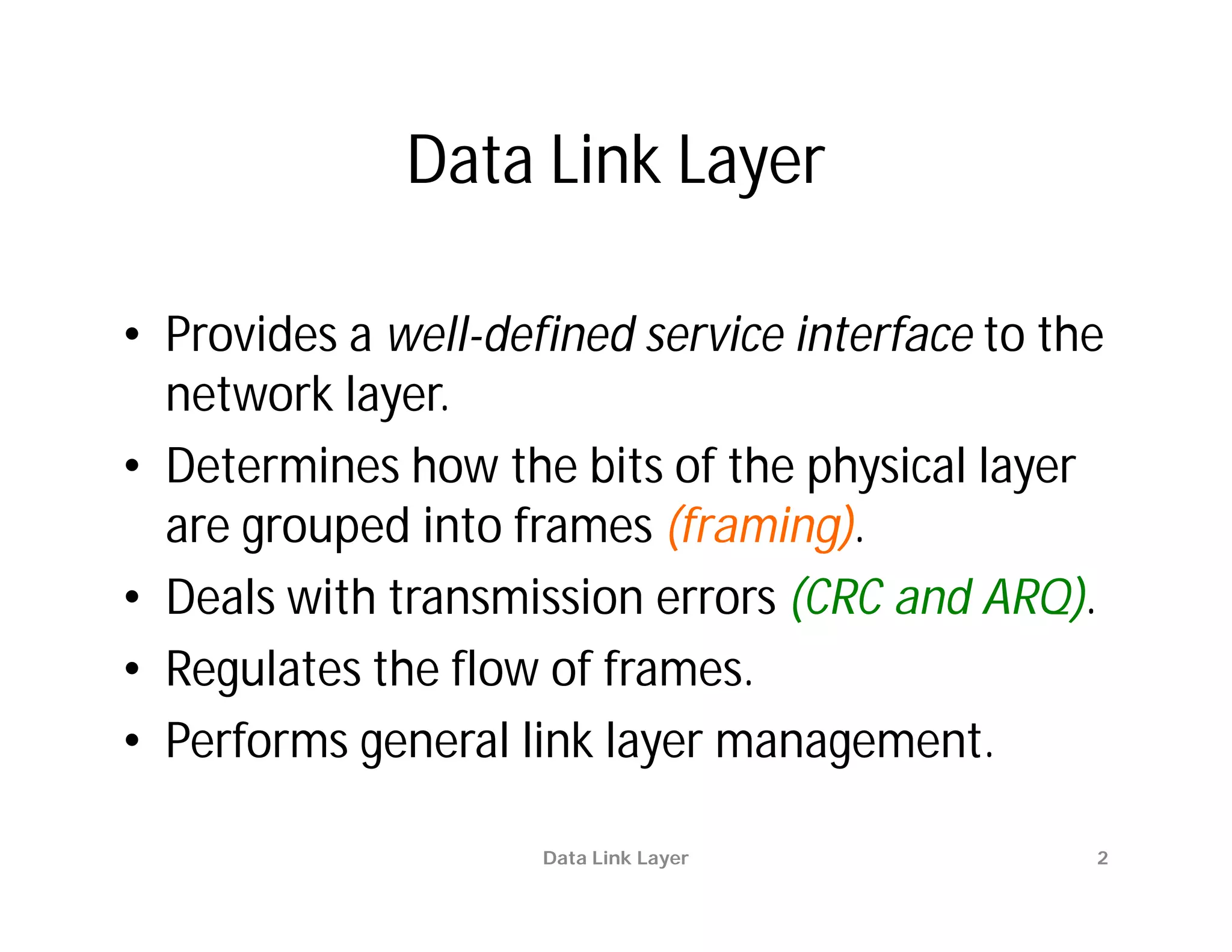
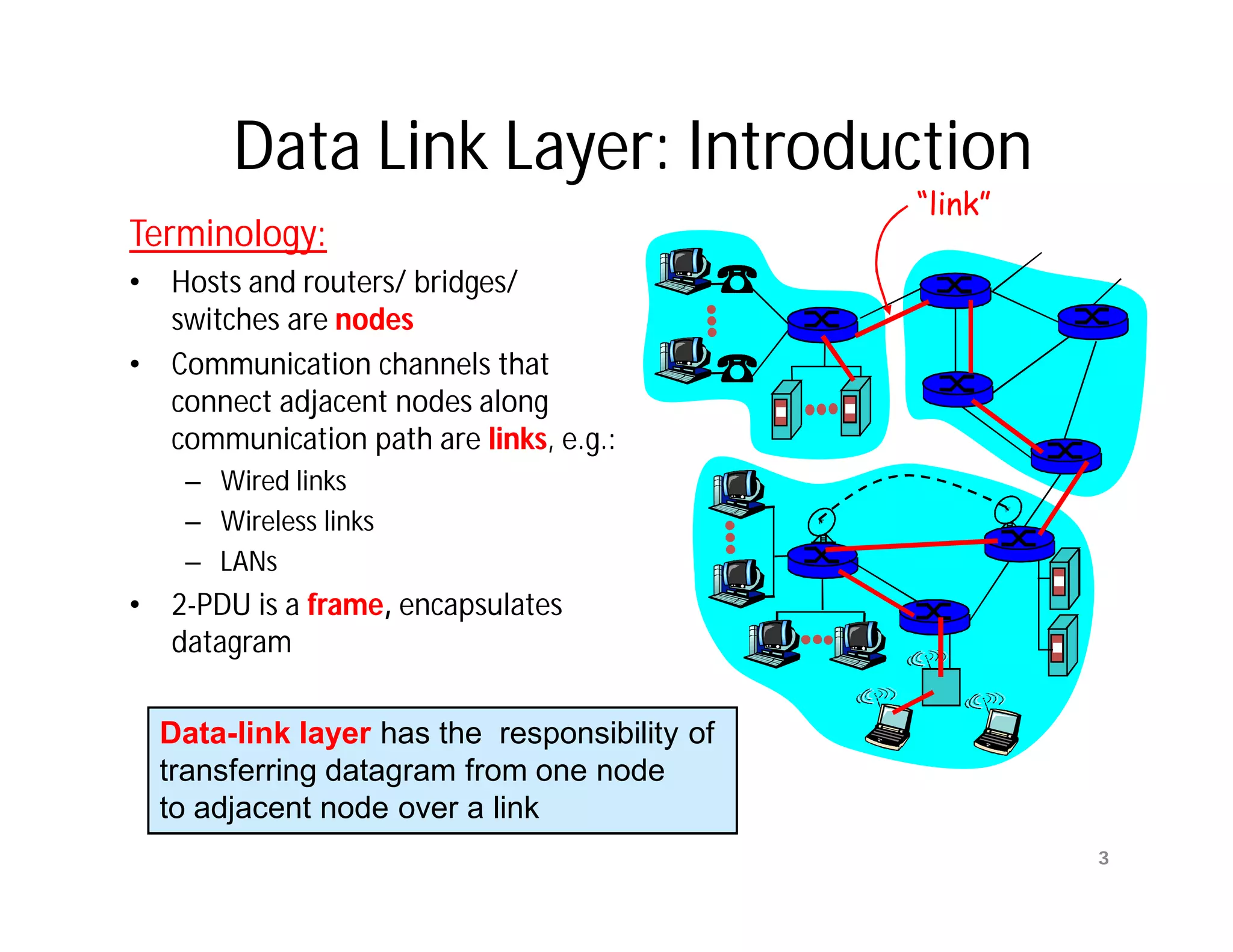
The document summarizes key aspects of the data link layer. It discusses how the data link layer provides a well-defined interface to the network layer, deals with frame transmission and errors, and regulates frame flow. It also describes common data link layer functions like framing, error detection, flow control, and link management. Finally, it discusses different data link protocols and how they handle issues like channel access, error handling, and window flow control.
![Ambiguities with Stop-and-Wait
[unnumbered frames]
(a) Frame 1 lost Time-out
time
A frame frame frame frame
0 1 1 2
ACK ACK
B
(b) ACK lost Time-out
time
A frame frame frame frame
0 1 1 2
ACK ACK ACK
B
In parts (a) and (b) transmitting station A acts the same way, but part
(b) receiving station B accepts frame 1 twice.
Copyright ©2000 The McGraw Hill Companies Leon-Garcia & Widjaja: Communication Networks Figure 5.9
Data Link Layer
15](https://image.slidesharecdn.com/networkinglecture4datalinklayerbymamunsir-120306220832-phpapp01/75/Networking-lecture-4-Data-Link-Layer-by-Mamun-sir-15-2048.jpg)
![PAR [OLD] problem
Ambiguities when ACKs are not numbered
time-out
time
A frame
0 frame frame frame
0 1 2
ACK
ACK
B
Transmitting station A misinterprets duplicate ACKs
Copyright ©2000 The McGraw Hill Companies Leon-Garcia & Widjaja: Communication Networks Figure 5.10
Data Link Layer 16](https://image.slidesharecdn.com/networkinglecture4datalinklayerbymamunsir-120306220832-phpapp01/75/Networking-lecture-4-Data-Link-Layer-by-Mamun-sir-16-2048.jpg)
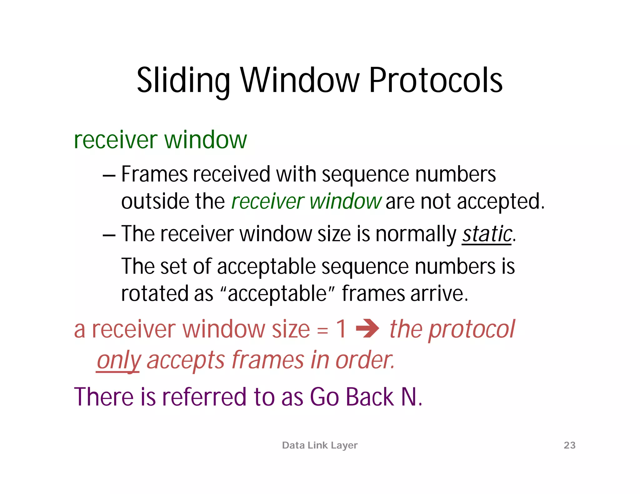
![Sliding Window Protocols
[Tanenbaum]
• Must be able to transmit data in both
directions.
• Choices for utilization of the reverse channel:
– mix DATA frames with ACK frames.
– Piggyback the ACK
• Receiver waits for DATA traffic in the opposite direction.
• Use the ACK field in the frame header to send sequence
number of frame being ACKed.
– better use of the channel capacity.
Data Link Layer 18](https://image.slidesharecdn.com/networkinglecture4datalinklayerbymamunsir-120306220832-phpapp01/75/Networking-lecture-4-Data-Link-Layer-by-Mamun-sir-18-2048.jpg)

![Chapter5[one.]](https://cdn.slidesharecdn.com/ss_thumbnails/chapter5one-110822150657-phpapp01-thumbnail.jpg?width=640&height=640&fit=bounds)


![Chapter4[one.]](https://cdn.slidesharecdn.com/ss_thumbnails/chapter4one-110822150650-phpapp02-thumbnail.jpg?width=640&height=640&fit=bounds)


![Unit 2 [autosaved]](https://cdn.slidesharecdn.com/ss_thumbnails/unit-2autosaved-210914023404-thumbnail.jpg?width=640&height=640&fit=bounds)