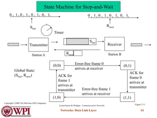
The document discusses various aspects of the data link layer, including:
1. The data link layer provides a well-defined interface to the network layer, deals with transmission errors, regulates frame flow, and performs link management.
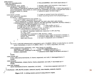
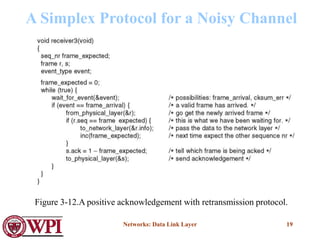
2. It determines how bits are grouped into frames, applies techniques like CRC for error detection and ARQ for error recovery.
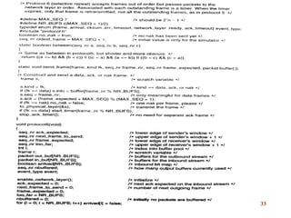
3. Sliding window protocols allow simultaneous transmission of data in both directions using sequence numbers and acknowledgments to regulate flow, prevent ambiguity, and ensure reliable delivery.
![Networks: Data Link Layer 13
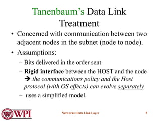
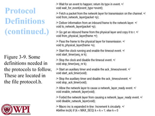
(a) Frame 1 lost
A
B
frame
0
frame
1
ACK
frame
1
ACK
time
Time-out
frame
2
(b) ACK lost
A
B
frame
0
frame
1
ACK
frame
1
ACK
time
Time-out
frame
2
ACK
In parts (a) and (b) transmitting station A acts the same way, but part (b)
receiving station B accepts frame 1 twice.
Figure 5.9
Ambiguities with Stop-and-Wait
[unnumbered frames]
Leon-Garcia & Widjaja: Communication Networks
Copyright ©2000 The McGraw Hill Companies](https://image.slidesharecdn.com/datalinklayer-220719152637-6b001aa1/85/Data_Link_Layer-ppt-13-320.jpg)
![Networks: Data Link Layer 15
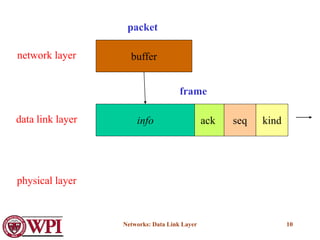
#define MAX_SEQ 1
typedef enum {frame_arrival, cksum_err, timeout} event_type;
include “protocol.h”
void sender_par (void)
{
seq_nr next_frame_to_send;
frame s;
packet buffer;
event_type event;
next_frame_to_send = 0;
from_network_layer (&buffer);
while (true)
{ s.info = buffer;
s.seq = next_frame_to_send;
to_physical_layer (&s);
start_timer (s.seq);
wait_for_event(&event);
if (event == frame_arrival) {
from_network_layer (&buffer);
inc (next_frame_to_send);
}
}
}
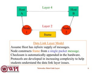
Protocol 3
(PAR) Positive ACK
with Retransmission
[Old Tanenbaum Version]](https://image.slidesharecdn.com/datalinklayer-220719152637-6b001aa1/85/Data_Link_Layer-ppt-15-320.jpg)
![Networks: Data Link Layer 16
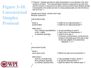
void receiver_par (void)
{
seq_nr next_frame_to_send;
frame r, s;
event_type event;
frame_expected = 0;
while (true)
{ wait_for_event (&event);
if (event == frame_arrival)
{ from_physical_layer (&r);
if (r.seq == frame_expected) {
to_network_layer(&r.info);
inc (frame_expected);
}
to_physical_layer (&s); /* Note – no sequence number on ACK */
}
}
}
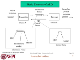
Protocol 3
(PAR) Positive ACK
with Retransmission
[Old Tanenbaum Version]](https://image.slidesharecdn.com/datalinklayer-220719152637-6b001aa1/85/Data_Link_Layer-ppt-16-320.jpg)
![Networks: Data Link Layer 17
A
B
frame
0 frame
0
ACK
frame
1
ACK
time
time-out
frame
2
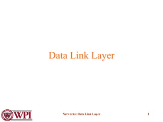
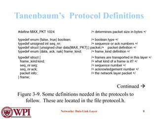
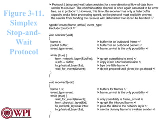
Transmitting station A misinterprets duplicate ACKs
Figure 5.10
Leon-Garcia & Widjaja: Communication Networks
Copyright ©2000 The McGraw Hill Companies
PAR [OLD] problem
Ambiguities when ACKs are not numbered](https://image.slidesharecdn.com/datalinklayer-220719152637-6b001aa1/85/Data_Link_Layer-ppt-17-320.jpg)

![Networks: Data Link Layer 20
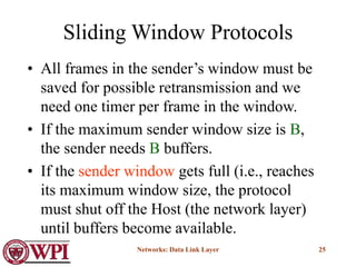
Sliding Window Protocols
[Tanenbaum]
• Must be able to transmit data in both directions.
• Choices for utilization of the reverse channel:
– mix DATA frames with ACK frames.
– Piggyback the ACK
• Receiver waits for DATA traffic in the opposite direction.
• Use the ACK field in the frame header to send sequence
number of frame being ACKed.
– better use of the channel capacity.](https://image.slidesharecdn.com/datalinklayer-220719152637-6b001aa1/85/Data_Link_Layer-ppt-20-320.jpg)