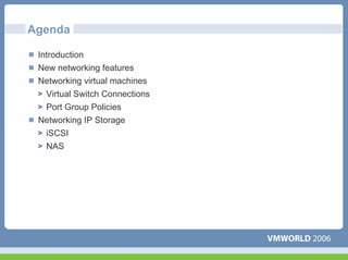
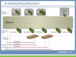
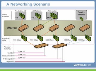
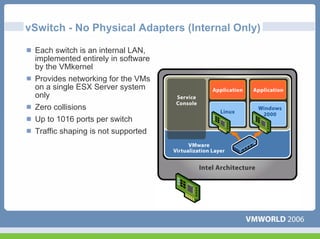
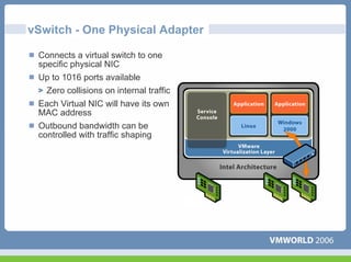
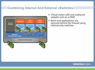
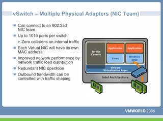
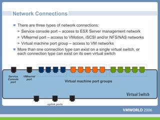
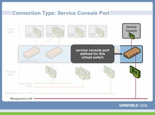
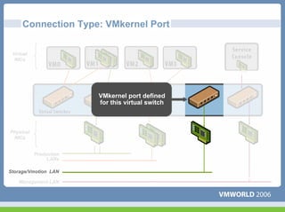
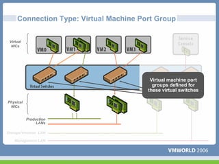
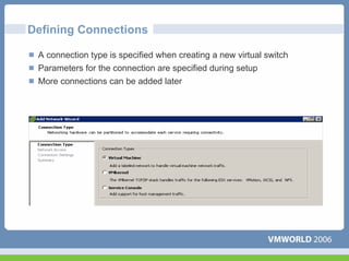
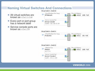
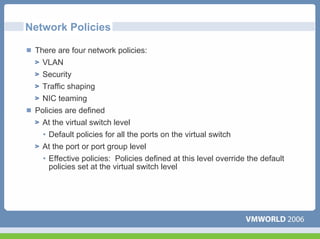
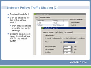
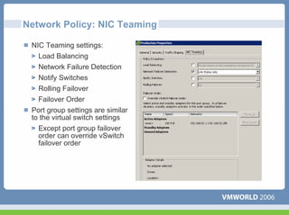
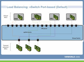
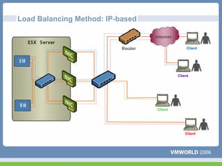
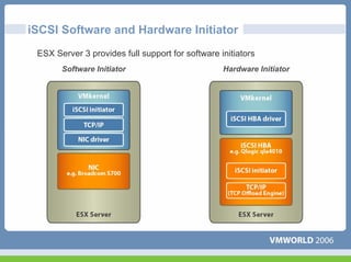
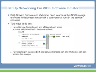
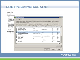
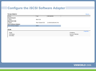
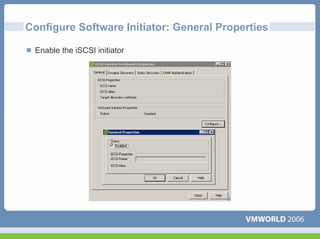
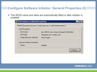
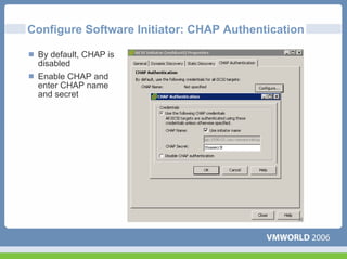
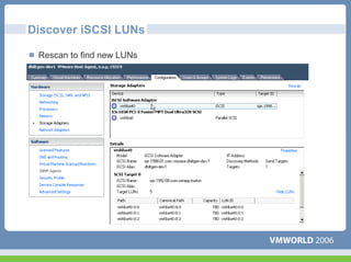
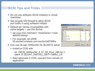
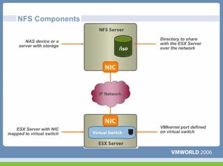
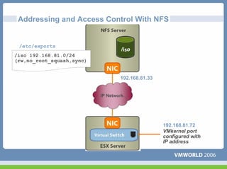
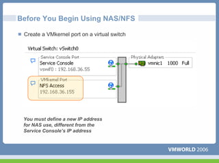
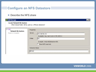
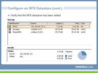
Networking Virtual Machines


                              Jon Hall
                              Technical Trainer
Agenda

 Introduction
 New networking features
 Networking virtual machines
   Virtual Switch Connections
  Port Group Policies
 Networking IP Storage
  iSCSI
  NAS
A networking Scenario
                 Production VM     NAT client     NAT router

Virtual
Machines


Physical
NICs        1000 Mbps            1000 Mbps      1000 Mbps      100 Mbps   100 Mbps


 Physical
 Switches
                    VLAN 101
      Test LAN
                    VLAN 102
Production LAN
                    VLAN 103
IP Storage LAN
     Mgmt LAN
A Networking Scenario
                 Production VM     NAT client     NAT router

Virtual
Machines


Physical
NICs        1000 Mbps            1000 Mbps      1000 Mbps      100 Mbps   100 Mbps


 Physical
 Switches
                    VLAN 101
      Test LAN
                    VLAN 102
Production LAN
                    VLAN 103
IP Storage LAN
     Mgmt LAN
vSwitch - No Physical Adapters (Internal Only)

 Each switch is an internal LAN,
 implemented entirely in software
 by the VMkernel
 Provides networking for the VMs
 on a single ESX Server system
 only
 Zero collisions
 Up to 1016 ports per switch
 Traffic shaping is not supported
vSwitch - One Physical Adapter

 Connects a virtual switch to one
 specific physical NIC
 Up to 1016 ports available
  Zero collisions on internal traffic
 Each Virtual NIC will have its own
 MAC address
 Outbound bandwidth can be
 controlled with traffic shaping
Combining Internal And External vSwitches

                          Virtual switch with one outbound
                          adapter acts as a DMZ
                          Back-end applications are
                          secured behind the firewall using
                          internal-only switches
vSwitch – Multiple Physical Adapters (NIC Team)

 Can connect to an 802.3ad
 NIC team
 Up to 1016 ports per switch
  Zero collisions on internal traffic
 Each Virtual NIC will have its own
 MAC address
 Improved network performance by
 network traffic load distribution
 Redundant NIC operation
 Outbound bandwidth can be
 controlled with traffic shaping
Connections
Network Connections

      There are three types of network connections:
        Service console port – access to ESX Server management network
        VMkernel port – access to VMotion, iSCSI and/or NFS/NAS networks
        Virtual machine port group – access to VM networks
      More than one connection type can exist on a single virtual switch, or
      each connection type can exist on its own virtual switch


Service   VMkernel
Console     port
 port                                 Virtual machine port groups


                       uplink ports
Connection Type: Service Console Port

 Virtual
  NICs


                             service console port
                               defined for this
                                virtual switch


Physical
 NICs


           Production
                LANs

Storage/Vmotion LAN

    Management LAN
Connection Type: VMkernel Port

 Virtual
  NICs


                        VMkernel port defined
                        for this virtual switch


Physical
 NICs


           Production
                LANs

Storage/Vmotion LAN

    Management LAN
Connection Type: Virtual Machine Port Group

 Virtual
  NICs


                                         Virtual machine port
                                          groups defined for
                                        these virtual switches

Physical
 NICs


           Production
                LANs

Storage/Vmotion LAN

    Management LAN
Defining Connections

 A connection type is specified when creating a new virtual switch
 Parameters for the connection are specified during setup
 More connections can be added later
Naming Virtual Switches And Connections

 All virtual switches are
 known as vSwitch#
 Every port or port group
 has a network label
 Service console ports are
 known as vSwif#
Policies
Network Policies

 There are four network policies:
   VLAN
   Security
   Traffic shaping
  NIC teaming
 Policies are defined
  At the virtual switch level
   • Default policies for all the ports on the virtual switch
   At the port or port group level
   • Effective policies: Policies defined at this level override the default
     policies set at the virtual switch level
Network Policy: VLANs

 Virtual LANs (VLANs) allow the creation of multiple logical LANs within
 or across physical network segments
 VLANs free network administrators from the limitations of physical
 network configuration
 VLANs provide several important benefits
  Improved security: the switch only presents frames to those stations in
  the right VLANs
  Improved performance: each VLAN is its own broadcast domain
  Lower cost: less hardware required for multiple LANs
 ESX Server includes support for IEEE 802.1Q VLAN Tagging
Network Policy: VLANs (2)

 Virtual switch tagging
   Packets leaving a VM are
   tagged as they pass though the
   virtual switch
   Packets are cleared (untagged)
   as they return to the VM
   Little impact on performance
Network Policy: Security

 Administrators can configure Layer 2 Ethernet security options at the
 virtual switch and at the port groups
 There are three
 security policy
 exceptions:
   Promiscuous
   Mode
   MAC Address
   Changes
   Forged
   Transmits
Network Policy: Traffic Shaping

 Network traffic shaping is a mechanism for controlling a VM’s outbound
 network bandwidth
 Average rate, peak rate, and burst size are configurable
Network Policy: Traffic Shaping (2)

 Disabled by default
 Can be enabled for
 the entire virtual
 switch
   Port group settings
   override the switch
   settings
 Shaping parameters
 apply to each virtual
 NIC in the virtual
 switch
Network Policy: NIC Teaming

 NIC Teaming settings:
   Load Balancing
   Network Failure Detection
   Notify Switches
   Rolling Failover
   Failover Order
 Port group settings are similar
 to the virtual switch settings
   Except port group failover
   order can override vSwitch
   failover order
Load Balancing: vSwitch Port-based (Default)

Virtual
 NICs


                                VM ports

                 uplink ports


Teamed
physical
 NICs
Load Balancing: Source MAC-based

                                   Internet

                          Router                   Client


                                              Client


                                    Client


                                                  Client
Load Balancing Method: IP-based

                                    Internet

                           Router                   Client


                                               Client


                                     Client


                                                   Client
Detecting And Handling Network Failure

 Network failure is detected by the VMkernel, which monitors the following:
  Link state only
  Link state + beaconing
 Switches can be notified whenever
   There is a failover event
   A new virtual NIC is connected to the virtual switch
   Updates switch tables and minimizes failover latency
 Failover is implemented by the VMkernel based upon configurable
 parameters
   Failover order: Explicit list of preferred links (uses highest-priority link
   which is up)
   • Maintains load balancing configuration
   • Good if using a lower bandwidth standby NIC
   Rolling failover -- preferred uplink list sorted by uptime
Multiple Policies Applied To A Single Team

 Different port groups within a vSwitch can implement different
 networking policies
   This includes NIC teaming policies
 Example: different active/standby NICs for different port groups of a
 switch using NIC teaming
                                  VM ports

  1    2       3      4   5   6    7         8       9         10        11          12         13           14

                                                     Active                          Standby


                                                 A        B         C            D         E             F

                                                 Standby                Active                 Standby


  A    B      C       D   E   F                  A        B         C            D         E             F

           uplink ports                                       Standby                          Active


                                                 A        B         C            D         E             F
IP Storage
What is iSCSI?

 A SCSI transport protocol, enabling access to storage devices over
 standard TCP/IP networks
    Maps SCSI block-oriented storage over TCP/IP
    Similar to mapping SCSI over Fibre Channel
 “Initiators”, such as an iSCSI HBA in an ESX Server, send SCSI
 commands to “targets”, located in iSCSI storage systems


                                                     Block storage


                              IP
How is iSCSI Used With ESX Server?

 Boot ESX Server from iSCSI storage
   Using hardware initiator only
 Create a VMFS on an iSCSI LUN
   To hold VM State, ISO images, and templates
 Allows VM access to a raw iSCSI LUN
 Allows VMotion migration of a VM whose disk
 resides on an iSCSI LUN
Components of an iSCSI SAN


                                                      Targets


                             IP Network


                                                     Initiators

                                    * Software implementation
Addressing in an iSCSI SAN
                                  iqn – iSCSI Qualified Name
  iSCSI target name
  iqn.1992-08.com.netapp:stor1

  iSCSI alias
  stor1

  IP address
  192.168.36.101


  iSCSI initiator name
  iqn.1998-01.com.vmware:train1           IP Network


  iSCSI alias
  train1

  IP address
  192.168.36.88
How iSCSI LUNs Are Discovered

 Two discovery methods are
 supported:
    Static Configuration
    SendTargets
 iSCSI device returns its target info
 as well as any additional target
 info that it knows about.                                     192.168.36.101:3260


                                                  IP Network


                                    SendTargets                SendTargets
                                        request                response

                      iSCSI target
                      192.168.36.101:3260
Multipathing With iSCSI

 SendTargets advertises multiple
 routes
   It reports different IP addresses
   to allow different paths to the
   iSCSI LUNs
 Routing done via IP network
 For the software initiator
   Counts as one network
   interface
   NIC teaming and multiple            IP Network
   SPs allow for multiple paths
 Currently supported via mru
 policy only
iSCSI Software and Hardware Initiator
 ESX Server 3 provides full support for software initiators
       Software Initiator                         Hardware Initiator
Set Up Networking For iSCSI Software Initiator

 Both Service Console and VMkernel need to access the iSCSI storage
 (software initiator uses vmkiscsid, a daemon that runs in the service
 console)
 Two ways to do this:
 1.   Have Service Console port and VMkernel port share
      a virtual switch and be in the same subnet


 2.   Have routing in place so both the Service Console port and VMkernel port can
      access the storage
Enable the Software iSCSI Client
Configure the iSCSI Software Adapter
Configure Software Initiator: General Properties

 Enable the iSCSI initiator
Configure Software Initiator: General Properties (2)

 The iSCSI name and alias are automatically filled in after initiator is
 enabled
Configure Software Initiator: Dynamic Discovery

 In the Dynamic
 Discovery tab, enter
 the IP address of
 each target server for
 initiator to establish a
 discovery session
 All available targets
 returned by the target
 server show up in the
 Static Discovery tab
Configure Software Initiator: CHAP Authentication

 By default, CHAP is
 disabled
 Enable CHAP and
 enter CHAP name
 and secret
Discover iSCSI LUNs

 Rescan to find new LUNs
iSCSI Tips and Tricks

 Do not use software iSCSI initiators in virtual
 machines
 Set console OS firewall to allow iSCSI
 port traffic if using software initiator
 Default iqn names incompatible with
 some targets – use this format
   iqn.yyyy-mm.<domain>.<hostname>:<user
   defined string>
   For example: iqn.2006-
   03.esxtest.vmware.com:esx3a-0a97886a.
 Can use QLogic SANsurfer for QLA4010 setup
  Install on COS with:
  • sh ./iSCSI_SANsurfer_4_01_00_linux_x86.bin -i
    silent -D SILENT_INSTALL_SET="QMSJ_LA"
   Start iqlremote in COS, connect from remote UI
   application
What is NAS and NFS?

 What is NAS?
  Network-Attached Storage
  Storage shared over the network at a filesystem level
 Why use NAS?
   A low-cost, moderate-performance option
   Less infrastructure investment required than with Fibre Channel
 There are two key NAS protocols:
   NFS (the “Network File System”)
  SMB (Windows networking, also known as “CIFS”)
 Major NAS appliances support both NFS and SMB
  Notably those from Network Appliance and EMC
 Server operating systems also support both
How is NAS Used With ESX Server?

 The VMkernel only supports NFS
   More specifically NFS version 3, carried over TCP
 NFS volumes are treated just like VMFS volumes in
 Fibre Channel or iSCSI storage
   Any can hold VMs’ running virtual disks
   Any can hold ISO images
   Any can hold VM templates
 Virtual machines with virtual disks on NAS storage can be VMotioned,
 subject to the usual constraints
   Compatible CPUs
   All needed networks and storage must be visible at destination
NFS Components

                                        Directory to share
        NAS device or a
                                        with the ESX Server
     server with storage
                                        over the network


                           IP Network


   ESX Server with NIC                  VMkernel port defined
mapped to virtual switch                on virtual switch
Addressing and Access Control With NFS


 /etc/exports
/iso 192.168.81.0/24
(rw,no_root_squash,sync)


                                   192.168.81.33


                           IP Network


                                                   192.168.81.72
                                                   VMkernel port
                                                   configured with
                                                   IP address
Before You Begin Using NAS/NFS

 Create a VMkernel port on a virtual switch


 You must define a new IP address
 for NAS use, different from the
 Service Console’s IP address
Configure an NFS Datastore

 Describe the NFS share
Configure an NFS Datastore (cont.)

 Verify that the NFS datastore has been added
Questions
Some or all of the features in this document may be representative of
feature areas under development. Feature commitments must not be
included in contracts, purchase orders, or sales agreements of any kind.
Technical feasibility and market demand will affect final delivery.

Network policies

  • 1.
    Networking Virtual Machines Jon Hall Technical Trainer
  • 2.
    Agenda Introduction Newnetworking features Networking virtual machines Virtual Switch Connections Port Group Policies Networking IP Storage iSCSI NAS
  • 3.
    A networking Scenario Production VM NAT client NAT router Virtual Machines Physical NICs 1000 Mbps 1000 Mbps 1000 Mbps 100 Mbps 100 Mbps Physical Switches VLAN 101 Test LAN VLAN 102 Production LAN VLAN 103 IP Storage LAN Mgmt LAN
  • 4.
    A Networking Scenario Production VM NAT client NAT router Virtual Machines Physical NICs 1000 Mbps 1000 Mbps 1000 Mbps 100 Mbps 100 Mbps Physical Switches VLAN 101 Test LAN VLAN 102 Production LAN VLAN 103 IP Storage LAN Mgmt LAN
  • 5.
    vSwitch - NoPhysical Adapters (Internal Only) Each switch is an internal LAN, implemented entirely in software by the VMkernel Provides networking for the VMs on a single ESX Server system only Zero collisions Up to 1016 ports per switch Traffic shaping is not supported
  • 6.
    vSwitch - OnePhysical Adapter Connects a virtual switch to one specific physical NIC Up to 1016 ports available Zero collisions on internal traffic Each Virtual NIC will have its own MAC address Outbound bandwidth can be controlled with traffic shaping
  • 7.
    Combining Internal AndExternal vSwitches Virtual switch with one outbound adapter acts as a DMZ Back-end applications are secured behind the firewall using internal-only switches
  • 8.
    vSwitch – MultiplePhysical Adapters (NIC Team) Can connect to an 802.3ad NIC team Up to 1016 ports per switch Zero collisions on internal traffic Each Virtual NIC will have its own MAC address Improved network performance by network traffic load distribution Redundant NIC operation Outbound bandwidth can be controlled with traffic shaping
  • 9.
  • 10.
    Network Connections There are three types of network connections: Service console port – access to ESX Server management network VMkernel port – access to VMotion, iSCSI and/or NFS/NAS networks Virtual machine port group – access to VM networks More than one connection type can exist on a single virtual switch, or each connection type can exist on its own virtual switch Service VMkernel Console port port Virtual machine port groups uplink ports
  • 11.
    Connection Type: ServiceConsole Port Virtual NICs service console port defined for this virtual switch Physical NICs Production LANs Storage/Vmotion LAN Management LAN
  • 12.
    Connection Type: VMkernelPort Virtual NICs VMkernel port defined for this virtual switch Physical NICs Production LANs Storage/Vmotion LAN Management LAN
  • 13.
    Connection Type: VirtualMachine Port Group Virtual NICs Virtual machine port groups defined for these virtual switches Physical NICs Production LANs Storage/Vmotion LAN Management LAN
  • 14.
    Defining Connections Aconnection type is specified when creating a new virtual switch Parameters for the connection are specified during setup More connections can be added later
  • 15.
    Naming Virtual SwitchesAnd Connections All virtual switches are known as vSwitch# Every port or port group has a network label Service console ports are known as vSwif#
  • 16.
  • 17.
    Network Policies Thereare four network policies: VLAN Security Traffic shaping NIC teaming Policies are defined At the virtual switch level • Default policies for all the ports on the virtual switch At the port or port group level • Effective policies: Policies defined at this level override the default policies set at the virtual switch level
  • 18.
    Network Policy: VLANs Virtual LANs (VLANs) allow the creation of multiple logical LANs within or across physical network segments VLANs free network administrators from the limitations of physical network configuration VLANs provide several important benefits Improved security: the switch only presents frames to those stations in the right VLANs Improved performance: each VLAN is its own broadcast domain Lower cost: less hardware required for multiple LANs ESX Server includes support for IEEE 802.1Q VLAN Tagging
  • 19.
    Network Policy: VLANs(2) Virtual switch tagging Packets leaving a VM are tagged as they pass though the virtual switch Packets are cleared (untagged) as they return to the VM Little impact on performance
  • 20.
    Network Policy: Security Administrators can configure Layer 2 Ethernet security options at the virtual switch and at the port groups There are three security policy exceptions: Promiscuous Mode MAC Address Changes Forged Transmits
  • 21.
    Network Policy: TrafficShaping Network traffic shaping is a mechanism for controlling a VM’s outbound network bandwidth Average rate, peak rate, and burst size are configurable
  • 22.
    Network Policy: TrafficShaping (2) Disabled by default Can be enabled for the entire virtual switch Port group settings override the switch settings Shaping parameters apply to each virtual NIC in the virtual switch
  • 23.
    Network Policy: NICTeaming NIC Teaming settings: Load Balancing Network Failure Detection Notify Switches Rolling Failover Failover Order Port group settings are similar to the virtual switch settings Except port group failover order can override vSwitch failover order
  • 24.
    Load Balancing: vSwitchPort-based (Default) Virtual NICs VM ports uplink ports Teamed physical NICs
  • 25.
    Load Balancing: SourceMAC-based Internet Router Client Client Client Client
  • 26.
    Load Balancing Method:IP-based Internet Router Client Client Client Client
  • 27.
    Detecting And HandlingNetwork Failure Network failure is detected by the VMkernel, which monitors the following: Link state only Link state + beaconing Switches can be notified whenever There is a failover event A new virtual NIC is connected to the virtual switch Updates switch tables and minimizes failover latency Failover is implemented by the VMkernel based upon configurable parameters Failover order: Explicit list of preferred links (uses highest-priority link which is up) • Maintains load balancing configuration • Good if using a lower bandwidth standby NIC Rolling failover -- preferred uplink list sorted by uptime
  • 28.
    Multiple Policies AppliedTo A Single Team Different port groups within a vSwitch can implement different networking policies This includes NIC teaming policies Example: different active/standby NICs for different port groups of a switch using NIC teaming VM ports 1 2 3 4 5 6 7 8 9 10 11 12 13 14 Active Standby A B C D E F Standby Active Standby A B C D E F A B C D E F uplink ports Standby Active A B C D E F
  • 29.
  • 30.
    What is iSCSI? A SCSI transport protocol, enabling access to storage devices over standard TCP/IP networks Maps SCSI block-oriented storage over TCP/IP Similar to mapping SCSI over Fibre Channel “Initiators”, such as an iSCSI HBA in an ESX Server, send SCSI commands to “targets”, located in iSCSI storage systems Block storage IP
  • 31.
    How is iSCSIUsed With ESX Server? Boot ESX Server from iSCSI storage Using hardware initiator only Create a VMFS on an iSCSI LUN To hold VM State, ISO images, and templates Allows VM access to a raw iSCSI LUN Allows VMotion migration of a VM whose disk resides on an iSCSI LUN
  • 32.
    Components of aniSCSI SAN Targets IP Network Initiators * Software implementation
  • 33.
    Addressing in aniSCSI SAN iqn – iSCSI Qualified Name iSCSI target name iqn.1992-08.com.netapp:stor1 iSCSI alias stor1 IP address 192.168.36.101 iSCSI initiator name iqn.1998-01.com.vmware:train1 IP Network iSCSI alias train1 IP address 192.168.36.88
  • 34.
    How iSCSI LUNsAre Discovered Two discovery methods are supported: Static Configuration SendTargets iSCSI device returns its target info as well as any additional target info that it knows about. 192.168.36.101:3260 IP Network SendTargets SendTargets request response iSCSI target 192.168.36.101:3260
  • 35.
    Multipathing With iSCSI SendTargets advertises multiple routes It reports different IP addresses to allow different paths to the iSCSI LUNs Routing done via IP network For the software initiator Counts as one network interface NIC teaming and multiple IP Network SPs allow for multiple paths Currently supported via mru policy only
  • 36.
    iSCSI Software andHardware Initiator ESX Server 3 provides full support for software initiators Software Initiator Hardware Initiator
  • 37.
    Set Up NetworkingFor iSCSI Software Initiator Both Service Console and VMkernel need to access the iSCSI storage (software initiator uses vmkiscsid, a daemon that runs in the service console) Two ways to do this: 1. Have Service Console port and VMkernel port share a virtual switch and be in the same subnet 2. Have routing in place so both the Service Console port and VMkernel port can access the storage
  • 38.
    Enable the SoftwareiSCSI Client
  • 39.
    Configure the iSCSISoftware Adapter
  • 40.
    Configure Software Initiator:General Properties Enable the iSCSI initiator
  • 41.
    Configure Software Initiator:General Properties (2) The iSCSI name and alias are automatically filled in after initiator is enabled
  • 42.
    Configure Software Initiator:Dynamic Discovery In the Dynamic Discovery tab, enter the IP address of each target server for initiator to establish a discovery session All available targets returned by the target server show up in the Static Discovery tab
  • 43.
    Configure Software Initiator:CHAP Authentication By default, CHAP is disabled Enable CHAP and enter CHAP name and secret
  • 44.
    Discover iSCSI LUNs Rescan to find new LUNs
  • 45.
    iSCSI Tips andTricks Do not use software iSCSI initiators in virtual machines Set console OS firewall to allow iSCSI port traffic if using software initiator Default iqn names incompatible with some targets – use this format iqn.yyyy-mm.<domain>.<hostname>:<user defined string> For example: iqn.2006- 03.esxtest.vmware.com:esx3a-0a97886a. Can use QLogic SANsurfer for QLA4010 setup Install on COS with: • sh ./iSCSI_SANsurfer_4_01_00_linux_x86.bin -i silent -D SILENT_INSTALL_SET="QMSJ_LA" Start iqlremote in COS, connect from remote UI application
  • 46.
    What is NASand NFS? What is NAS? Network-Attached Storage Storage shared over the network at a filesystem level Why use NAS? A low-cost, moderate-performance option Less infrastructure investment required than with Fibre Channel There are two key NAS protocols: NFS (the “Network File System”) SMB (Windows networking, also known as “CIFS”) Major NAS appliances support both NFS and SMB Notably those from Network Appliance and EMC Server operating systems also support both
  • 47.
    How is NASUsed With ESX Server? The VMkernel only supports NFS More specifically NFS version 3, carried over TCP NFS volumes are treated just like VMFS volumes in Fibre Channel or iSCSI storage Any can hold VMs’ running virtual disks Any can hold ISO images Any can hold VM templates Virtual machines with virtual disks on NAS storage can be VMotioned, subject to the usual constraints Compatible CPUs All needed networks and storage must be visible at destination
  • 48.
    NFS Components Directory to share NAS device or a with the ESX Server server with storage over the network IP Network ESX Server with NIC VMkernel port defined mapped to virtual switch on virtual switch
  • 49.
    Addressing and AccessControl With NFS /etc/exports /iso 192.168.81.0/24 (rw,no_root_squash,sync) 192.168.81.33 IP Network 192.168.81.72 VMkernel port configured with IP address
  • 50.
    Before You BeginUsing NAS/NFS Create a VMkernel port on a virtual switch You must define a new IP address for NAS use, different from the Service Console’s IP address
  • 51.
    Configure an NFSDatastore Describe the NFS share
  • 52.
    Configure an NFSDatastore (cont.) Verify that the NFS datastore has been added
  • 53.
  • 54.
    Some or allof the features in this document may be representative of feature areas under development. Feature commitments must not be included in contracts, purchase orders, or sales agreements of any kind. Technical feasibility and market demand will affect final delivery.