Downloaded 86 times
![INTRODUCTION
Disclosure
The ideas described in this paper are
being considered to become part of a formal
set of public Remote PHY specifications.
The Remote PHY specifications are still
under development. The following represents
the author’s current thoughts on the
requirements, form, and functionality of the
Remote PHY protocol. Since actual bit
positions within the protocol are still being
finalized, they are not explicitly specified in
this white paper.
However, this white paper should be a
fairly accurate guide to what the Remote
PHY protocol can accomplish and how it
operates.
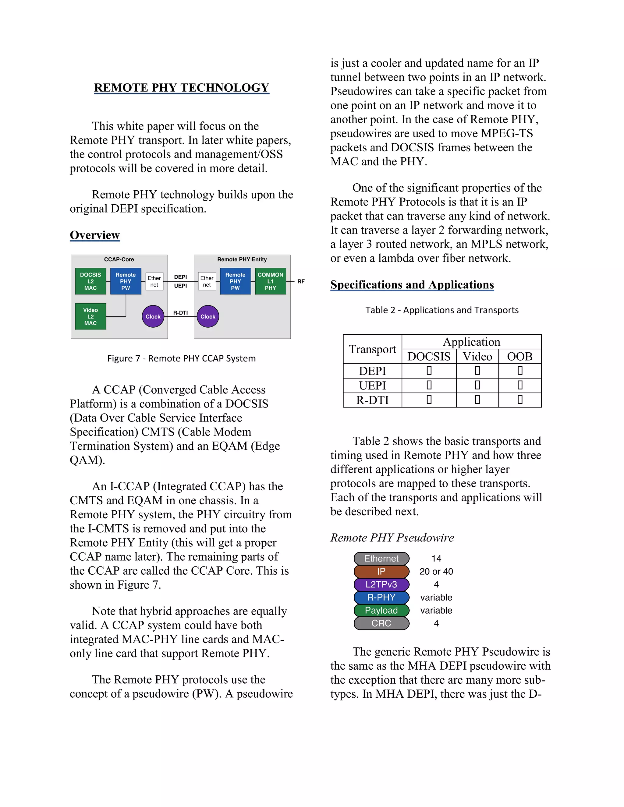
What is Remote PHY?
Figure 1 - Remote PHY CCAP Network
Remote PHY is an architectural strategy
that removes the PHY element from a
product and places that PHY element in a
separate access point that is interconnected
with an IP network (even simple Metro
Ethernet networks or just EPONs qualify as
they use IP packets). This is shown in Figure
1 and explained in the white paper [8].
Restated, Remote PHY allows you to put
your main chassis at one end of a network
and your PHY chip at the other end of the
network. This is a useful technique when the
PHY chip needs to be close to an access
network, but the desire is to put the
intelligence and complexity in a central
location that has more room and is more
serviceable.
Remote PHY infers centralized software.
The least amount of complexity is placed
remotely; the most amount of complexity is
retained centrally.
Remote PHY-like strategies (similar in
concept but different in implementation)
have been used in adjacent markets such as:
WiFi access points
LTE access points
Ethernet over Coax (EoC)
EPON over Coax (EPoC)
xDSL
Remote PHY in this context was applied
initially to a DOCSIS CMTS. Remote PHY
is also now being applied to traditional
MPEG-TS video and to out-of-band (OOB
signaling).
Remote PHY Lineage
The first instance of Remote PHY
technology was the Modular CMTS (M-
CMTS) specifications from CableLabs in
2005. Architecture and tutorial discussions of
M-CMTS can be found in white papers [11],
[12] and [13].
The specifications included:
DEPI – DOCSIS External PHY
Interface
DTI – DOCSIS Timing Interface
CCAP
Core
(MAC)
Service
Flow
Engine
CCAP
Access
Point
(PHY)
DOCSIS
CM
Digital Fiber
DOCSIS
Provisioning System
DOCSIS
Policy Server
DOCSIS
PacketCable
DOCSIS Signaling
Internet
MHAv2 Signaling
Coax](https://image.slidesharecdn.com/nctapapernonlinearfinal-140509160649-phpapp01/75/Remote-PHY-for-Converged-DOCSIS-Video-and-OOB-2-2048.jpg)
![plant design would be N+0 or N+1, meaning
an optical node plus no or one amplifier.
In a deep fiber plant, there are many
more optical nodes, head end optical lasers
and receivers, as well as CMTS ports to be
purchased. A conversion to digital fiber may
yield a better investment decision.
Digital forward and reverse paths are
interesting for technical and strategic
reasons. The technical reasons are:
Longer distances (80+ km vs. 40 km)
More wavelengths (80 vs. 16)
Lower cost optics (based upon 10G
Ethernet)
Higher throughput (more bits per
Hertz) if the DOCSIS 3.1 PHY is
located after the coax segment.
Lower maintenance costs
Higher Reliability
If the digital fiber is also an IP network
(or Metro Ethernet or EPON/GPON
network), then there are also additional
strategic benefits:
Compatibility with digital access
networks which are now appearing
internationally
Good scaling for deep fiber
The same IP-based access network can
be used for residential and commercial
use.
The same IP-based access network can
be used to support DOCSIS (with
Remote PHY) and fiber to the home
(FTTH).
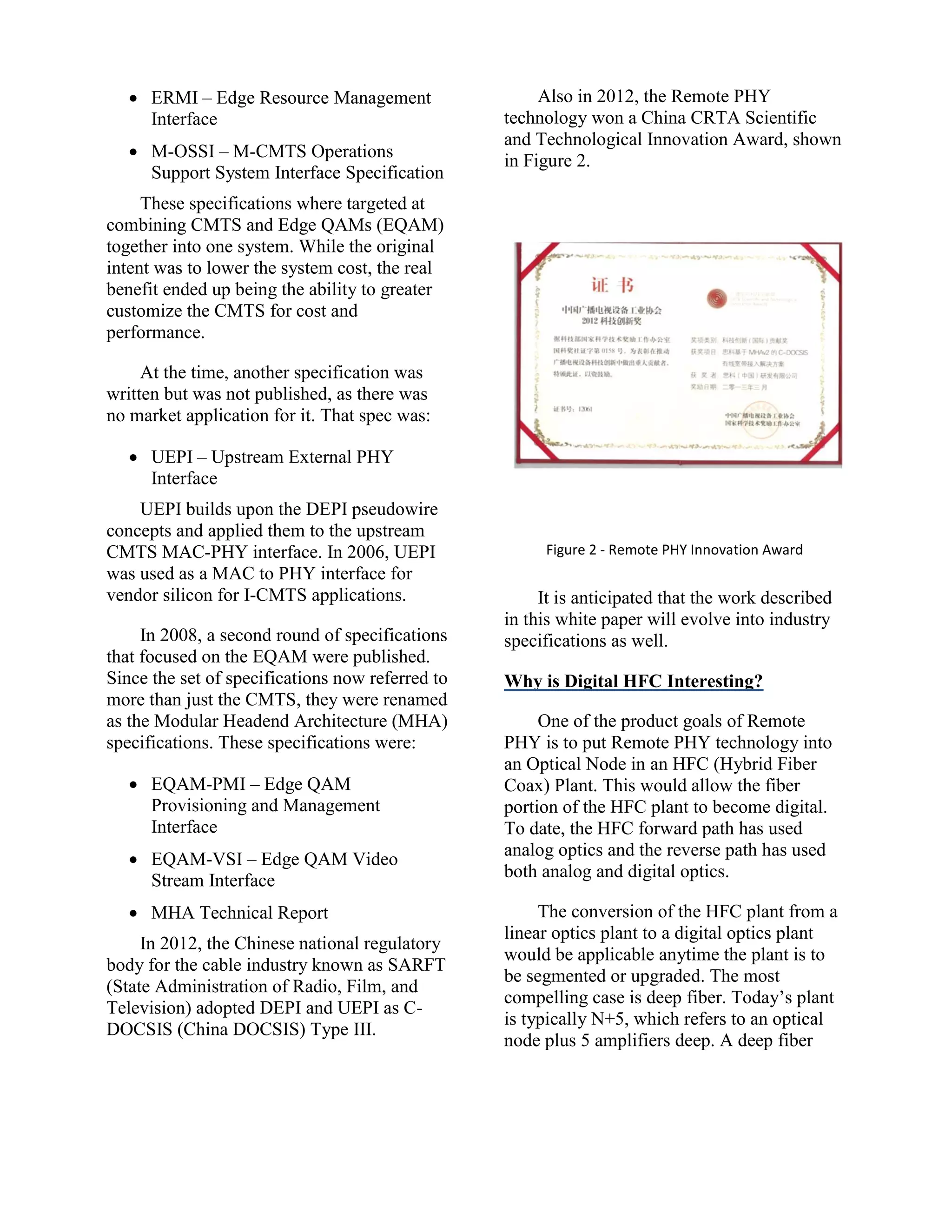
Review of Comparable Technologies
Table 1 - Technology Comparison
Criteria
BDR,
BDF
Remote
PHY
Remote
MAC
Remote
CMTS
IP
Network
No Yes Yes Yes
I-CMTS
impact
Low Low High Low
Remote
SW
0% 5% 50% 100%
Remote
HW
5% 10% 40% 100%
There are several ways to address the
market need for digital HFC. These methods
are shown in Table 1 and they are ranked to
several basic criteria that define them. [9]
BDR/BDF
The most basic approach would be to do
a baseband digital forward (BDF) in a similar
manner to how baseband digital reverse
(BDR) was done. This has been too costly to
date to do, but may become feasible in the
future. The main advantage of this approach
is that it is transparent to any modulation or
service that goes across it. The main
disadvantage is that it maintains a single hop
proprietary fiber interface. Even if BDF
where to adopt a network packet format, the
network traffic would be very high
bandwidth and continuously on 100% of the
time. It also does not allow the CMTS to
Remote PHY path to traverse a generic IP
network.
There are three variations on the
DOCSIS CMTS theme, all of which support
IP networking.
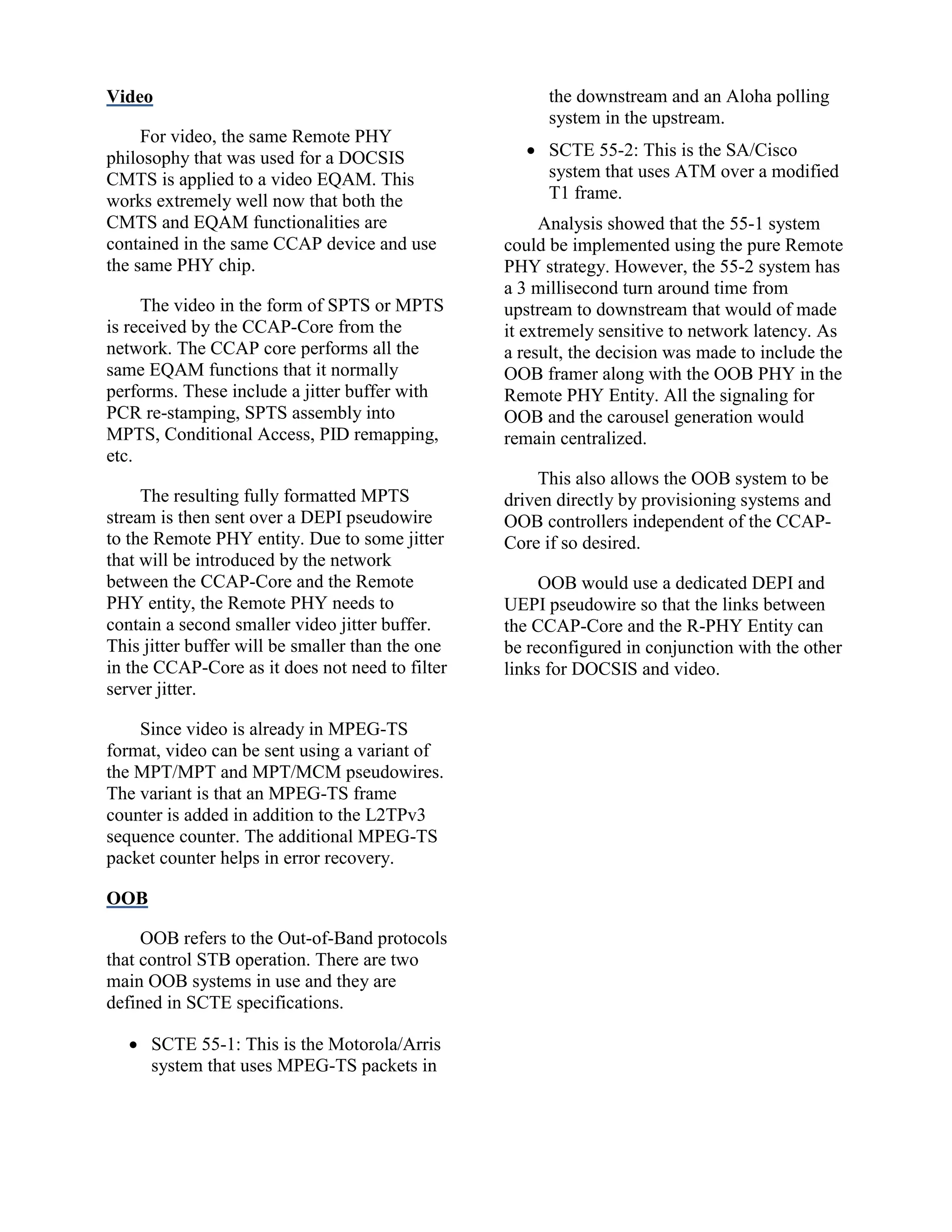
Remote PHY
Remote PHY, the subject of this white
paper, puts the bare minimum hardware and
software into a remote entity. Remote PHY](https://image.slidesharecdn.com/nctapapernonlinearfinal-140509160649-phpapp01/75/Remote-PHY-for-Converged-DOCSIS-Video-and-OOB-4-2048.jpg)
![system, it can be the interface between the
MAC chip and the PHY chip. In a Remote
PHY system, it is the protocol interface
between the MAC interface in the CCAP-
Core and the PHY chip in the Remote PHY
entity.
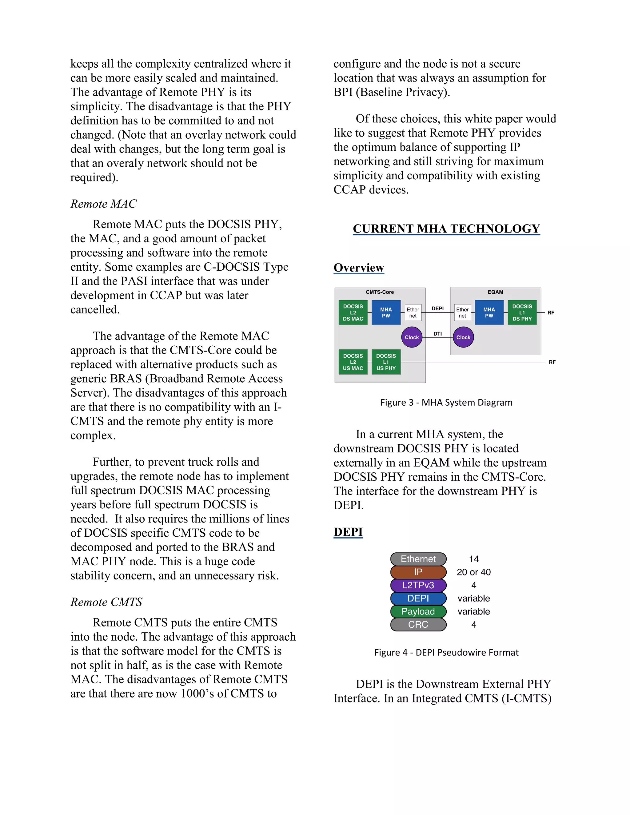
The general pseudowire format for DEPI
along with a byte count is shown in Figure 4.
The sub-elements of the DEPI packet are as
follows:
Ethernet header
IPv4 or IPv6 header
L2TPv3 header
DEPI header
DEPI Payload
CRC
The first three headers are well defined
by IEEE and IETF specifications. The
published version of DEPI does include an
optional UDP header ahead of the L2TPv3
header. This option was not used in practice
and will be eliminated from the specification.
This also simplifies the L2TPv3 header.
The L2TPv3 header contains a single 32-bit
session ID. If the session ID is all zeros, the
packet is a control plane packet. If the
session ID is non-zero, then it is a data
packet. The control plane will associate a
session ID with a pseudowire type and sub-
type. The base L2TPv3 protocol is in [20].
The format of the DEPI header is
specific to DEPI. The DEPI header also
specifies the format of the DEPI payload.
There are two DEPI pseudowire types.
D-MPT which is the DOCSIS MPEG
Transport pseudowire
PSP which is the Packet Streaming
Protocol pseudowire
Each pseudowire can have a sub-type.
Examples of sub-type are “DOCSIS 3.0
Downstream” and “DOCSIS 3.1
Downstream”. The significance is that the
pseudowire type is part of the normal
L2TPv3 control plane while the pseudowire
sub-type is advertised in the DEPI specific
extensions.
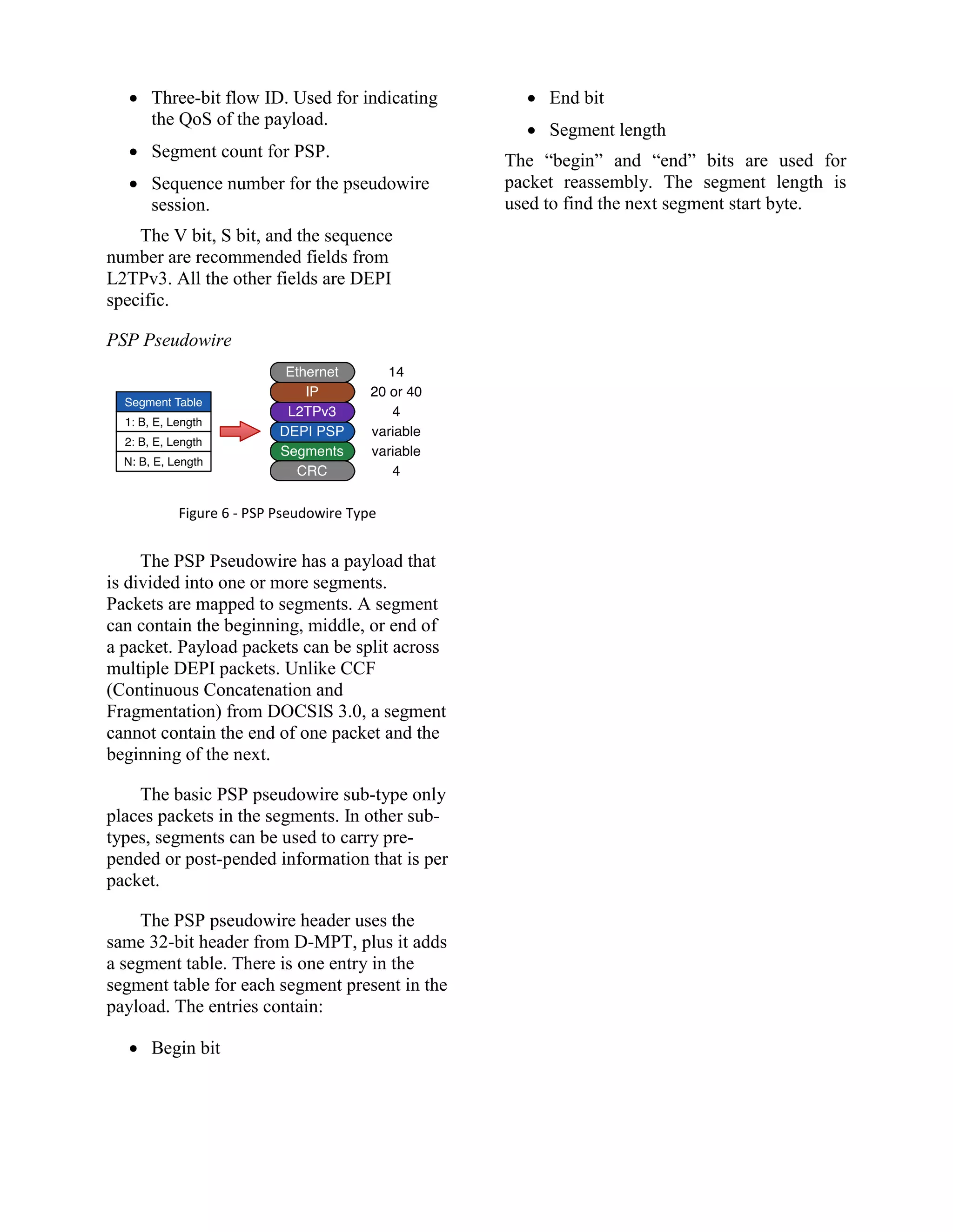
D-MPT Pseudowire
Figure 5 - D-MPT Pseudowire Type
The DOCSIS MPEG-TS pseudowire is
the only pseudowire that was deployed in
DOCSIS 3.0 based M-CMTS systems. As the
name implies, there is a DEPI header
followed by a number of 188 byte MPEG-TS
packets. For M-CMTS, the DEPI packet size
limited the number of MPEG-TS packets to
seven.
The D-MPT header is 32 bits in size and
contains the basic DEPI header that is used in
all the pseudowire types. It contains:
A V bit to permit L2TPv3 payload
multiplexing within an L2TPv3
session.
A S bit to indicate if the sequence field
is valid
Two H bits that allow DEPI payload
multiplexing within a DEPI session.
This is used for DLM, the DEPI
Latency Measurement packet.](https://image.slidesharecdn.com/nctapapernonlinearfinal-140509160649-phpapp01/75/Remote-PHY-for-Converged-DOCSIS-Video-and-OOB-6-2048.jpg)
![MPT and PSP pseudowire types. There are
now a collection of sub-types that add
extensions to D-MPT and PSP.
UEPI
Figure 8 - UEPI Pseudowire
UEPI is the Upstream External PHY
Interface. UEPI is new for Remote PHY and
was not part of the original M-CMTS and
MHA specifications.
UEPI is an extension to L2TPv3. UEPI
uses the PSP pseudowire type from DEPI
and uses the same control plane as DEPI.
UEPI has unique pseudowire types for the
upstream direction that are explained in a
later section. UEPI for DOCSIS 3.0 is
described in [1].
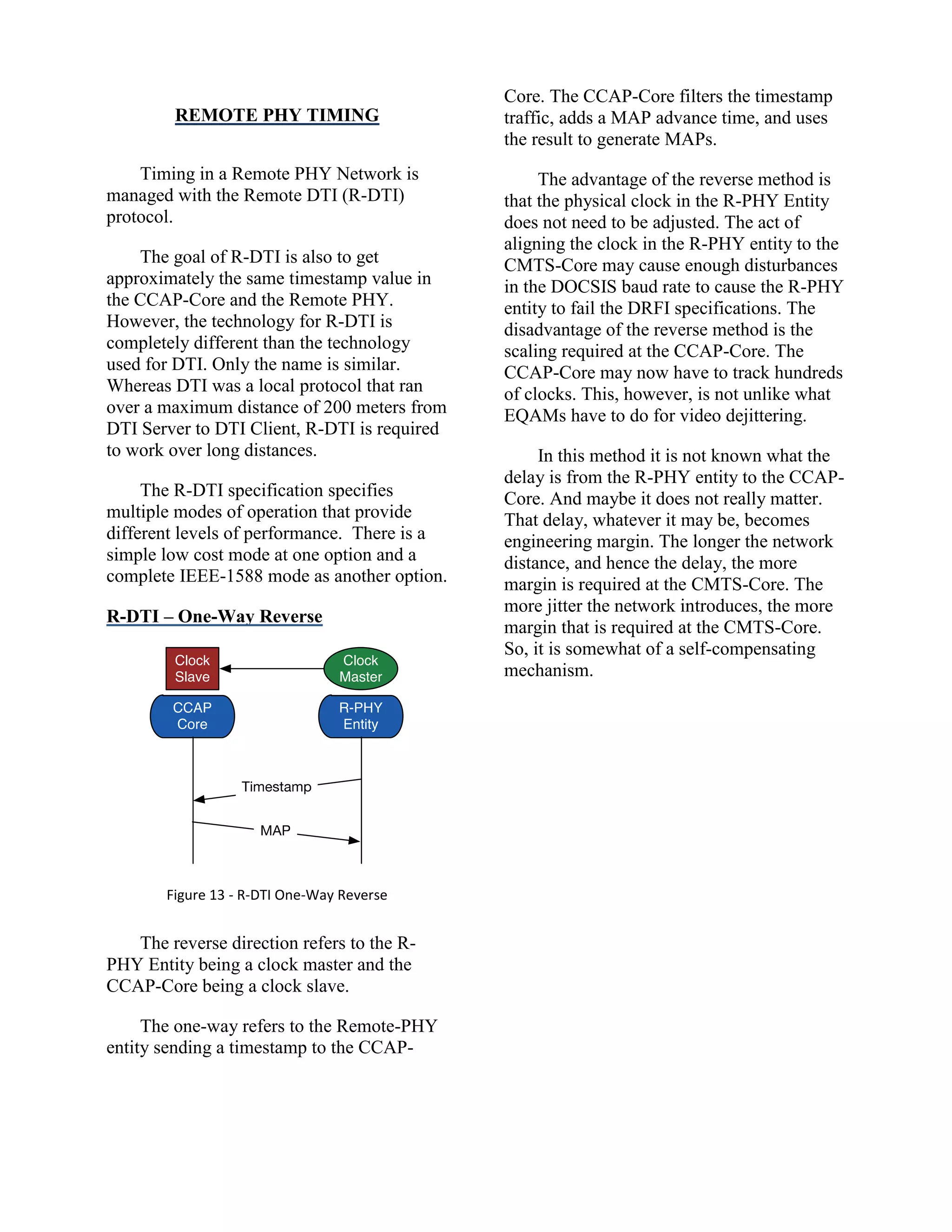
R-DTI
R-DTI is the Remote DOCSIS Timing
Interface. The local version, just known as
DTI, is part of the M-CMTS specifications.
The original DTI protocol defines how a
timing server can run timing to a CMTS-
Core and an EQAM and how both devices
can have the same timestamp. The DTI
protocol is described in [10].
R-OOB
R-OOB is Remote Out-of-Band. OOB is
the signaling channel in the downstream and
upstream that is used to control Set-Top
Boxes (STB).
R-OOB use DEPI and UEPI so that the
pseudowires can be setup and torn down with
the same control plane protocols as rest of
the Remote PHY Pseudowires. R-OOB is
carried as a separate specification since it is a
distinct and potentially separate application.
NEW PROTOCOL EXTENSIONS
Packet Length
DEPI was originally defined with a 1500
byte Ethernet packet. In D-MPT mode, this
allows for up to 7 MPEG-TS packets per
DEPI packet. In the new Remote PHY
specifications, that length will be increased to
approximately 2000 bytes. This will allow up
to 10 MPEG-TS packets per DEPI packet.
MPLS
Figure 9 - DEPI over MPLS
MPLS is Multiple Protocol Label
Switching, and is a method of moving
packets across a network using labels which
can be popped on and off at each network
forward point. MPLS routes are setup using
LDP, the Label Distribution Protocol. MPLS
routes are calculated using protocols such as
MPLS-TE that is MPLS Traffic Engineering.
Technically, there are two underlying
types of pseudowires used in network –
MPLS and L2TPv3. The MPLS pseudowire
is used for native MPLS networks and the
L2TPv3 pseudowire is used for native IP
networks. Each protocol has its own control
plane. If DEPI had been originally designed](https://image.slidesharecdn.com/nctapapernonlinearfinal-140509160649-phpapp01/75/Remote-PHY-for-Converged-DOCSIS-Video-and-OOB-9-2048.jpg)
![as an MPLS pseudowire, it would have
added protocol extensions to MPLS-TE.
Since DEPI is just an IP packet, it can be
sent over any network, including an MPLS
network. Since the DEPI control plane is
already well defined and working, the current
direction is to not rebuild DEPI with MPLS-
TE. Instead, the DEPI forwarding plane and
control plane will remain as L2TPv3 and will
(optionally) run on top of MPLS. This is
shown in Figure 9.
Thus, DEPI does not use an MPLS
pseudowire. DEPI uses an L2TPv3 based
pseudowire which can be run over an MPLS
network.
MCM: Multi-Channel MPT
Figure 10 - DEPI MPT/MCM Pseudowire
In the current usage of the MPT
pseudowire, there is one pseudowire for each
QAM channel in the Remote PHY. The
advantage of MPT is that it provides a simple
point-to-point connection from a MAC
channel to a PHY channel. The disadvantage
is that additional latency is incurred in
building up MPEG-TS packets into a DEPI
packet. The latency of ten MPEG-TS
packets at 1 Gbps is 1.6 usec.
While this is not much of an additional
delay, MCM also offers an improvement by
allowing multiple QAM channels to share the
same pseudowire. This also helps with
scaling. For example, instead of having 160
pseudowires for 160 QAM channels,
technically, there could be one really busy
DEPI pseudowire. Typically, there would be
a smaller number of DEPI pseudowires with
a number of pseudowires.
MCM is a sub-type of the main MPT
pseudowire. MCM uses a table in the DEPI
header that lists which MPEG-TS packet in
the DEPI payload goes to which QAM
Channel. A table format in the header is used
rather then tagging each MPEG-TS packet so
that in implementation, the table can be read
and then executed against the rest of the
packet. This is shown in Figure 10.
Note that while any number of QAM
channels can be supported within a
pseudowire, each DEPI packet can only
contain up to 10 MPEG-TS packets in one
packet at one time.
BFD
Figure 11 – DEPI or UEPI with BFD
BFD refers to Bi-Directional Forwarding
Detection. BFD is essentially a loopback
packet that can be used for testing data path
integrity. By integrating BFD directly into
the packet, the entire transmission path from
the DOCSIS MAC channel to Remote PHY
QAM channel can be tested.
Note that BFD can also be sent in a
stand-alone UDP packet. BFD is an industry
standard extension to L2TPv3 and applies to
all DEPI and UEPI pseudowires types and
sub-types. BFD is described in [17], [18] and
[19].](https://image.slidesharecdn.com/nctapapernonlinearfinal-140509160649-phpapp01/75/Remote-PHY-for-Converged-DOCSIS-Video-and-OOB-10-2048.jpg)
![DOCSIS 3.1
DOCSIS 3.1 is a new version of
DOCSIS that has recently been released from
CableLabs. DOCSIS 3.1 uses a new physical
layer based upon OFDM (Orthogonal
Frequency Division Multiplexing) and an
error correction scheme called LDPC (Low
Density Parity Check). The data path consists
of one or more OFDM channels. Each
OFDM channel has a PLC (PHY link
Channel) for initializing CMs (Cable
Modems). DOCSIS 3.1 is discussed in more
detail in [3], [4] and [5].
In DOCSIS 3.1, the downstream OFDM
channel is assigned a list of profiles. The
profile lists the modulation to be used for
each sub-carrier in an OFDM channel. The
profile can be different for each LDPC block
and is dependent upon which CM is
receiving the OFDM block. This is done to
allow the optimization of the transmission
path to those CMs that can tolerate a higher
modulation. The management of DOCSIS
3.1 profiles is described in [2].
The PLC Channel is composed of
message blocks (MB). The following
message blocks are defined in DOCSIS 3.1:
Timestamp MB
DLS (DOSIS Light Sleep Mode) MB
Trigger MB
Message Channel
Null MB
The timestamp MB is generated locally
at the Remote PHY. The other MBs are
transparently passed from the CCAP-Core to
the Remote PHY Entity.
In DOCSIS 3.1, the downstream and
upstream frequency ranges also can be
altered to provide more throughput. DOCSIS
3.1 can support 1 to 2.5 Gbps in the
upstream, and 5 to 10 Gbps in the
downstream. [7]
DS OFDM Channel Pseudowire
Each OFDM Channel is assigned to a
PSP pseudowire with a subtype of DOCSIS
3.1 Data Path. The PSP header is extended so
that its table contains the OFDM profile
number for each packet in the PSP stream.
DS PLC Channel Pseudowire
Each PLC is assigned to a PSP
pseudowire with a subtype of PLC. For the
DLS MB, Trigger MB and the Null MB, the
MBs are placed directly into a PSP segment
and referenced by the PSP table. A 32-bit
timestamp can optionally be prepended to a
segment. This is useful for the trigger MB.
The packets in the payload of the message
channel are mapped to PSP segments.
D3.1 Upstream Pseudowires
Figure 12 - DOCSIS 3.1 UEPI Pseudowires
There are a number of pseudowires
associated with the DOCSIS 3.1 Upstream.
All pseudowires have a pseudowire type of
PSP and each have a unique sub-type. The
DOCSIS 3.1 UEPI pseudowires are similar
to the DOCSIS 3.0 UEPI pseudowires, but
have differences in formats. The Probe PW is
unique to DOCSIS 3.1 Remote PHY.](https://image.slidesharecdn.com/nctapapernonlinearfinal-140509160649-phpapp01/75/Remote-PHY-for-Converged-DOCSIS-Video-and-OOB-11-2048.jpg)
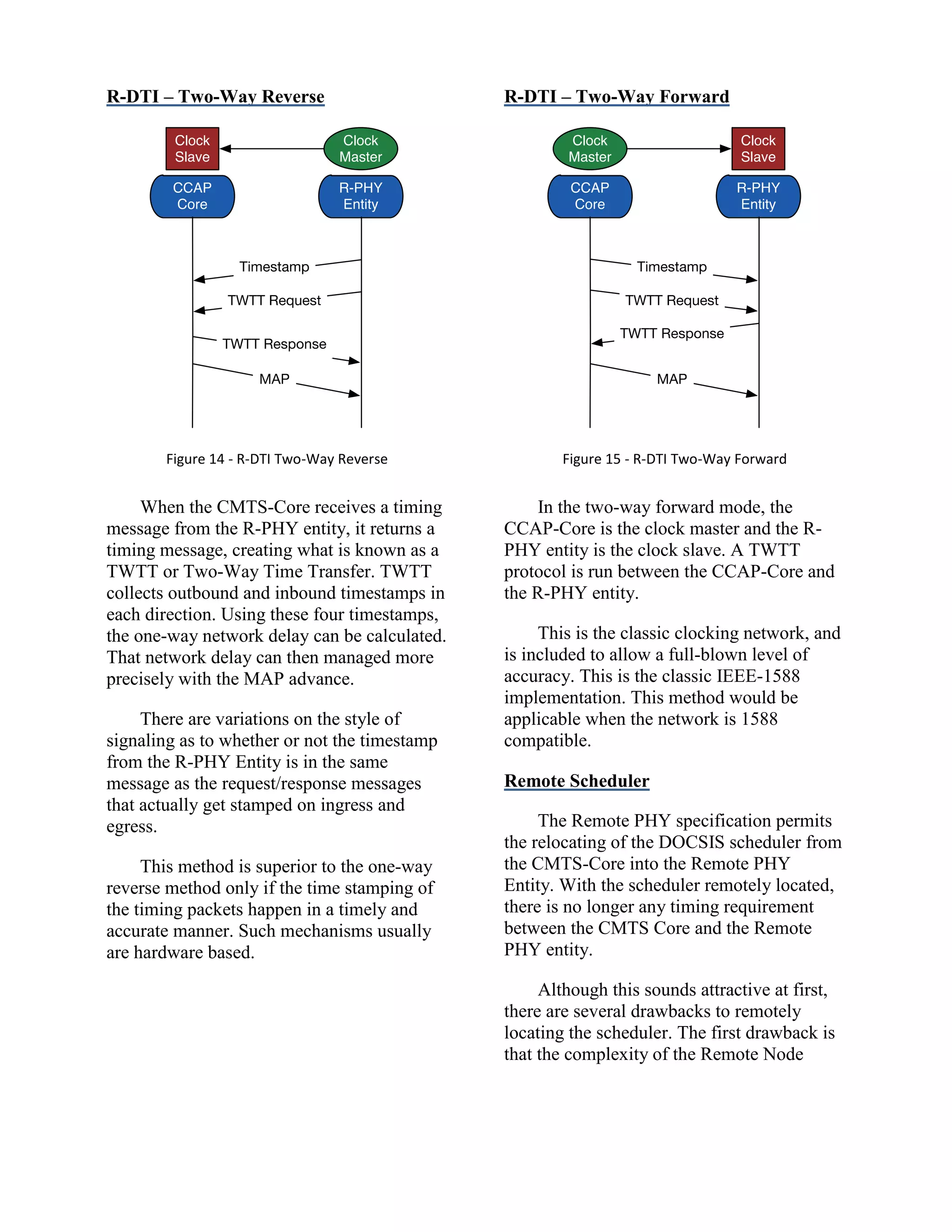
![increases. The Remote Node entity now
become subscriber aware and requires state
information, QoS information, policy
information and needs to track historical
information for implementing of rate
shaping. This is definitely an increased level
of complexity.
The second reason that a remote
scheduler is not attractive is interoperability.
If the CCAP-Core is from one vendor, the
scheduler and node are from another vendor,
and something goes wrong, who is at fault?
How is troubleshooting done without a
centralized scheduler as a reference point?
Our current analysis shows that a
centralized scheduler will work under
currently known network conditions and that
the timing design is quite manageable. (This
will be the subject of a future white paper).
The option for a remote scheduler is a future
option should it ever be needed.
Details
Packet Formats
The two-way forward method is
intended to be an IEEE-1588
implementation. It may also include a
Synchronous Ethernet (SyncE)
implementation for frequency alignment.
The one-way and two-way reverse
methods could be implemented with a light
version of IEEE-1588 or a Remote PHY
specific control packet.
Support for DTP
DTP is the DOCSIS Timing Protocol
that was developed by this author and is
being introduced with DOCSIS 3.1. DTP
allows a CM to provide timing services such
as IEEE-1588 and Synchronous Ethernet
derived from DOCSIS timing. This is
explained in a white paper study [6] and in
the DOCSIS 3.1 specification [14].
Distances
DOCSIS define a CMTS-to-CM, PHY-
to-PHY distance of 100 miles (160 km) for
DOCSIS 3.0 and 50 miles (80 km) for
DOCSIS 3.1. Remote PHY maintains these
distances.
Because Remote PHY separates the
DOCSIS MAC and PHY, there is an
additional distance specification. That is the
MAC-to-MAC, CMTS-Core to CM distance.
This distance is relevant when the CMTS-
Core is removed from the hub and placed in
the head end or regional data center.
In theory, there is no distance limitation
to R-DTI. In practice, longer distances add
jitter and latency that may impact services
such as scheduling. While the maximum
operating distance has not been chosen at the
time this paper was written, research is being
conducted to see if R-DTI and the scheduling
applications it supports could run over a
distance up to 2000 km. This number comes
from the Indian market. The Norway market
requires about 1500 km if everything was
driven out of Oslo.
That is more than 10x the original
DOCSIS distance of 160 km!
This additional distance is intended to
allow the CCAP-Core to be located at the
head end or regional data center instead of at
the hub site.
NEXT STEPS
This white paper defined the operation
of the Remote PHY transport. The next steps
will include:](https://image.slidesharecdn.com/nctapapernonlinearfinal-140509160649-phpapp01/75/Remote-PHY-for-Converged-DOCSIS-Video-and-OOB-15-2048.jpg)
![ agreeing on the bit definition of the
various protocol headers,
extending the DEPI control plane to
cover UEPI, and
defining a configuration and
operational model for the Remote PHY
entity.
SUMMARY
Remote PHY is an approach that literally
takes the PHY chip out of a box and puts it at
the end of an IP network. One of the
philosophies of Remote PHY is to put the
least amount of hardware and software at the
end point and keep the complexity
centralized.
Remote PHY infers centralized DOCSIS
software. This allows the same software
model to be used for I-CCAP and Remote
PHY CCAP. Remote PHY, I-CMTS and M-
CMTS can all co-exist in the same chassis
and use the same software base and
configuration systems. This is a very
powerful concept for feature velocity and
backwards compatibility.
Remote PHY works and works well. The
design of remote PHY is built on top of open
standards such as Ethernet, IP, L2TPv3, and
CableLabs MHA.
Remote PHY will allow CCAP devices
to be deployed in more creative manners
such as using digital fiber in the HFC plant.
For the Cable Operators, this will allow their
network to have higher performance with
lower OPEX, lower CAPEX, and an
evolutionary path the FTTH.
REFERENCES
Related Papers by the Same Author
[1] John T. Chapman, “DOCSIS Remote
PHY,” SCTE Cable-Tec Expo, October 21,
2013
[2] John T. Chapman, “The Power of
DOCSIS 3.1 Downstream Profiles”, NCTA
Spring Technical Forum, June 13, 2013
[3] John T. Chapman, “DOCSIS 3.1 –
Redefining the State of the Art”, Cable
Congress, March 6, 2013
[4] John T. Chapman, "What the Future
Holds for DOCSIS", Keynote speech, Light
Reading Conference, Denver, May 18, 2012
[5] John T. Chapman, Robert Howald, Mike
Emmendorfer, “Mission is Possible: an
Evolutionary Approach to Gigabit-Class
DOCSIS”, NCTA Spring Technical Forum,
May 12, 2012
[6] John T. Chapman, Rakesh Chopra,
Laurent Montini, “The DOCSIS Timing
Protocol – Generating Precision Timing
Services from a DOCSIS System”, NCTA
Spring Technical Forum, June 14, 2011
[7] John T. Chapman, “Taking the DOCSIS
Upstream to a Gigabit per Second”, NCTA
Spring Technical Forum, May 12, 2010
[8] John T. Chapman, Jeff Finkelstein,
“Maximizing Legacy and DOCSIS 3.0
Bandwidth in the Forward Path using M-
CMTS and EdgeQAM Technologies”, SCTE
Cable-Tec Expo, October 30, 2009
http://www.johntchapman.com/Legacy-and-
DOCSIS3-with-M-CMTS-WP-%282009-10-
30%29.pdf
[9] John T. Chapman, “Next Generation
CMTS – An Architectural Discussion”,](https://image.slidesharecdn.com/nctapapernonlinearfinal-140509160649-phpapp01/75/Remote-PHY-for-Converged-DOCSIS-Video-and-OOB-16-2048.jpg)
![SCTE Emerging Technologies, January 15,
2008
http://www.johntchapman.com/NG-CMTS-
WP-071125.pdf
[10]John T. Chapman, “DOCSIS Timing
Interface – Timing for DOCSIS Networks”,
National Institute of Standards and
Technology (NIST) Keynote Address, March
10, 2007
http://www.johntchapman.com/NIST-
jchapman-070310.pdf
[11]John T. Chapman, “Modular CMTS
Tutorial”, CableLabs Summit, December
2006
http://www.johntchapman.com/M-CMTS-
Tutorial-Public-070220a.pdf
[12]John T. Chapman, Andrew Page,
Carmelo Iaria, Glenn McGilvray,
“Transitioning to M-CMTS”, NCTA
National Show, April 2006
[13]John T. Chapman, “Modular CMTS
Architecture”, NCTA National Show, April
3, 2005
http://www.johntchapman.com/ncta-2005-
modular-cmts-wp.pdf
Related CableLabs Specifications
[14]“DOCSIS 3.1 MAC and Upper Layer
Protocols Interface Specification”, Revision
I02, CableLabs, March 20, 2014.
http://www.cablelabs.com/specification/mac-
and-upper-layer-protocols-interface-
specification/
[15]“DOCSIS Timing Interface (DTI)
Specification”, Revision I05, CableLabs,
December 9, 2008
http://www.cablelabs.com/specification/docsi
s-timing-interface-specification/
[16]“Downstream External PHY Interface
Specification”, Revision I08, CableLabs,
June 11, 2010
http://www.cablelabs.com/specification/dow
nstream-external-phy-interface-specification/
Related IETF Specifications
[17]David Katz, David Ward, “Bidirectional
Forwarding Detection (BFD)”, RFC-5880,
Internet Engineering Task Force (IETF),
June 2010
http://tools.ietf.org/html/rfc5880
[18]David Katz, David Ward, “Bidirectional
Forwarding Detection (BFD) for IPv4 and
IPv6”, RFC-5881, Internet Engineering Task
Force (IETF), June 2010
http://tools.ietf.org/html/rfc5881
[19]David Katz, David Ward, “Bidirectional
Forwarding Detection (BFD) for the
Pseudowire Virtual Circuit Connectivity
Verification”, RFC-5885, Internet
Engineering Task Force (IETF), June 2010
http://tools.ietf.org/html/rfc5885
[20]J. Lau, Mark Townsley, I. Goyret,
“Layer Two Tunneling Protocol – Version 3
(L2TPv3)”, RFC-3931, March 2005
http://tools.ietf.org/html/rfc3931](https://image.slidesharecdn.com/nctapapernonlinearfinal-140509160649-phpapp01/75/Remote-PHY-for-Converged-DOCSIS-Video-and-OOB-17-2048.jpg)

The document discusses Remote PHY, a technology that relocates the PHY circuit of cable systems to an access point in a network, facilitating improved efficiency and centralization of complexity. It builds on previous modular specifications and aims to support various applications such as DOCSIS, MPEG-TS video, and out-of-band signaling. Key components include the DEPI pseudowire interface, the implications of digital HFC networks, and the evolution of these specifications into formal standards.


![[Whitepaper] Cisco Vision: 5G - THRIVING INDOORS](https://cdn.slidesharecdn.com/ss_thumbnails/5granindoorv6final2-170215173927-thumbnail.jpg?width=640&height=640&fit=bounds)

![[Infographic] Cisco Visual Networking Index (VNI): Mobile-Connected Devices p...](https://cdn.slidesharecdn.com/ss_thumbnails/mobile-connecteddevicespercapita-160202160317-thumbnail.jpg?width=640&height=640&fit=bounds)
![[Infographic] Cisco Visual Networking Index (VNI): Mobile Users Growth](https://cdn.slidesharecdn.com/ss_thumbnails/mobileusersgrowth-160202160305-thumbnail.jpg?width=640&height=640&fit=bounds)


