Download as PDF, PPTX
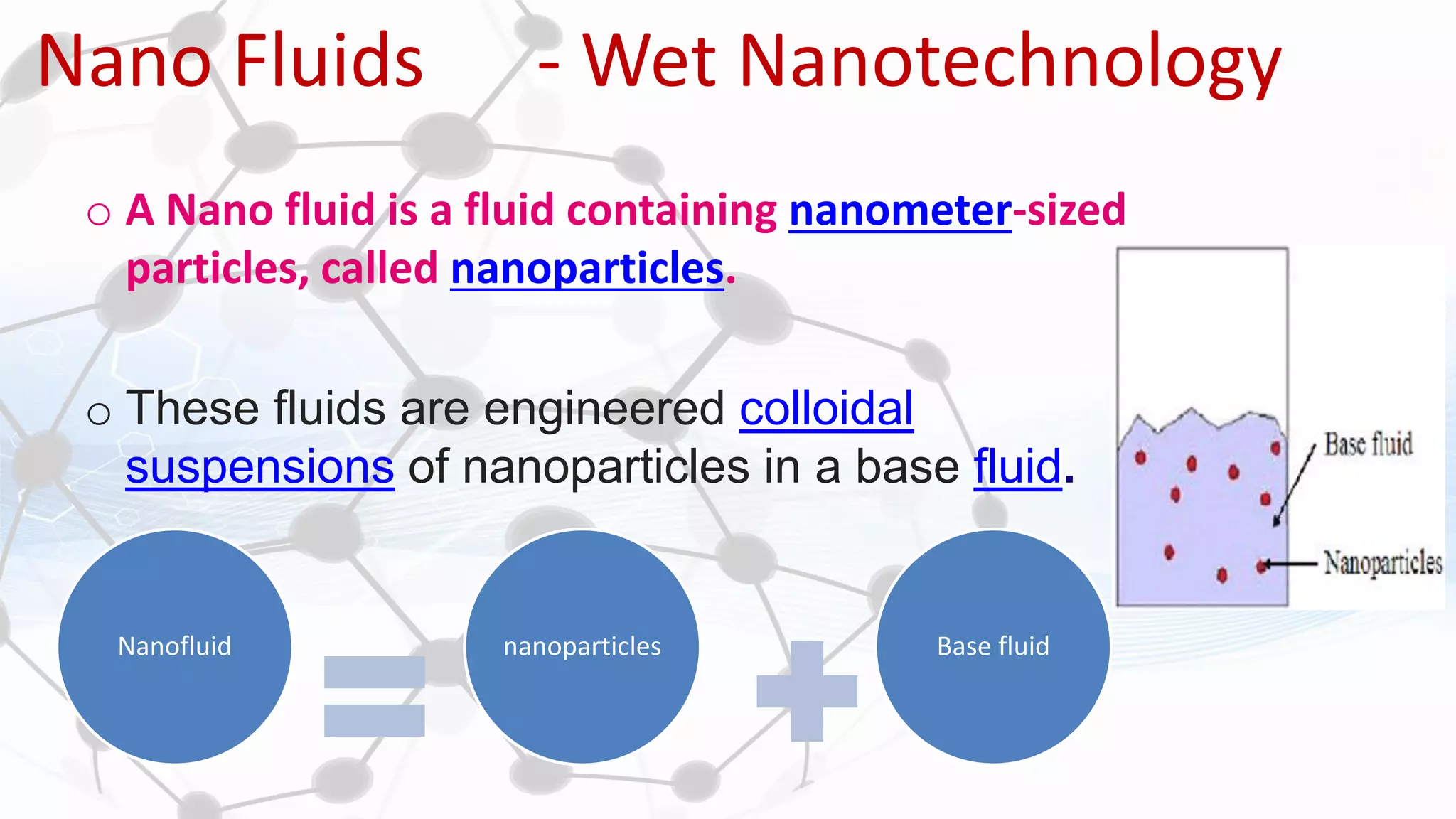


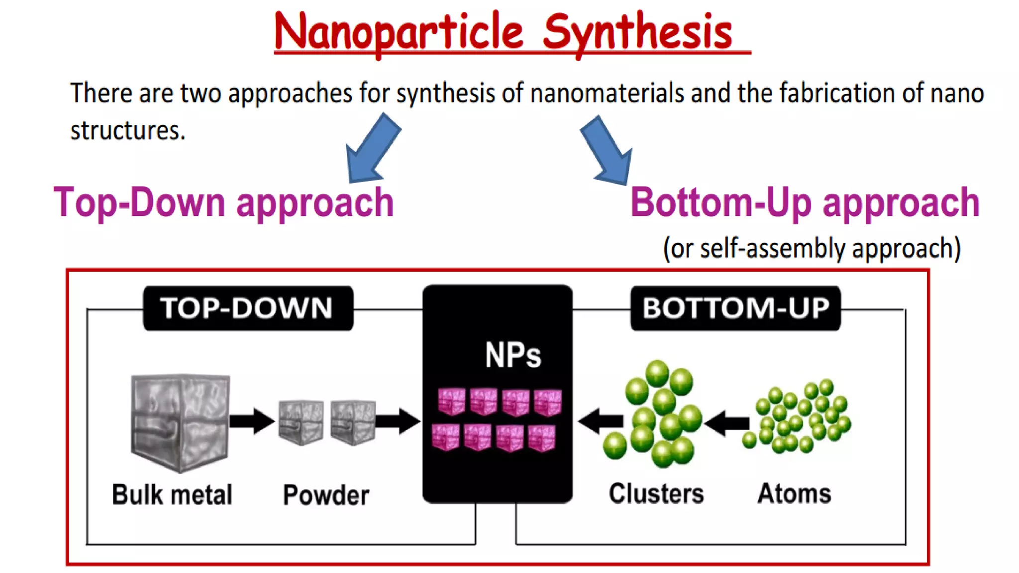


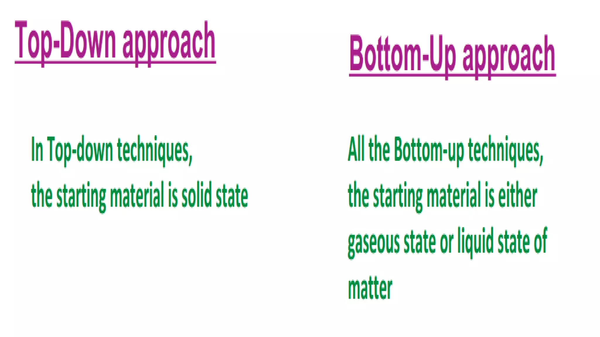


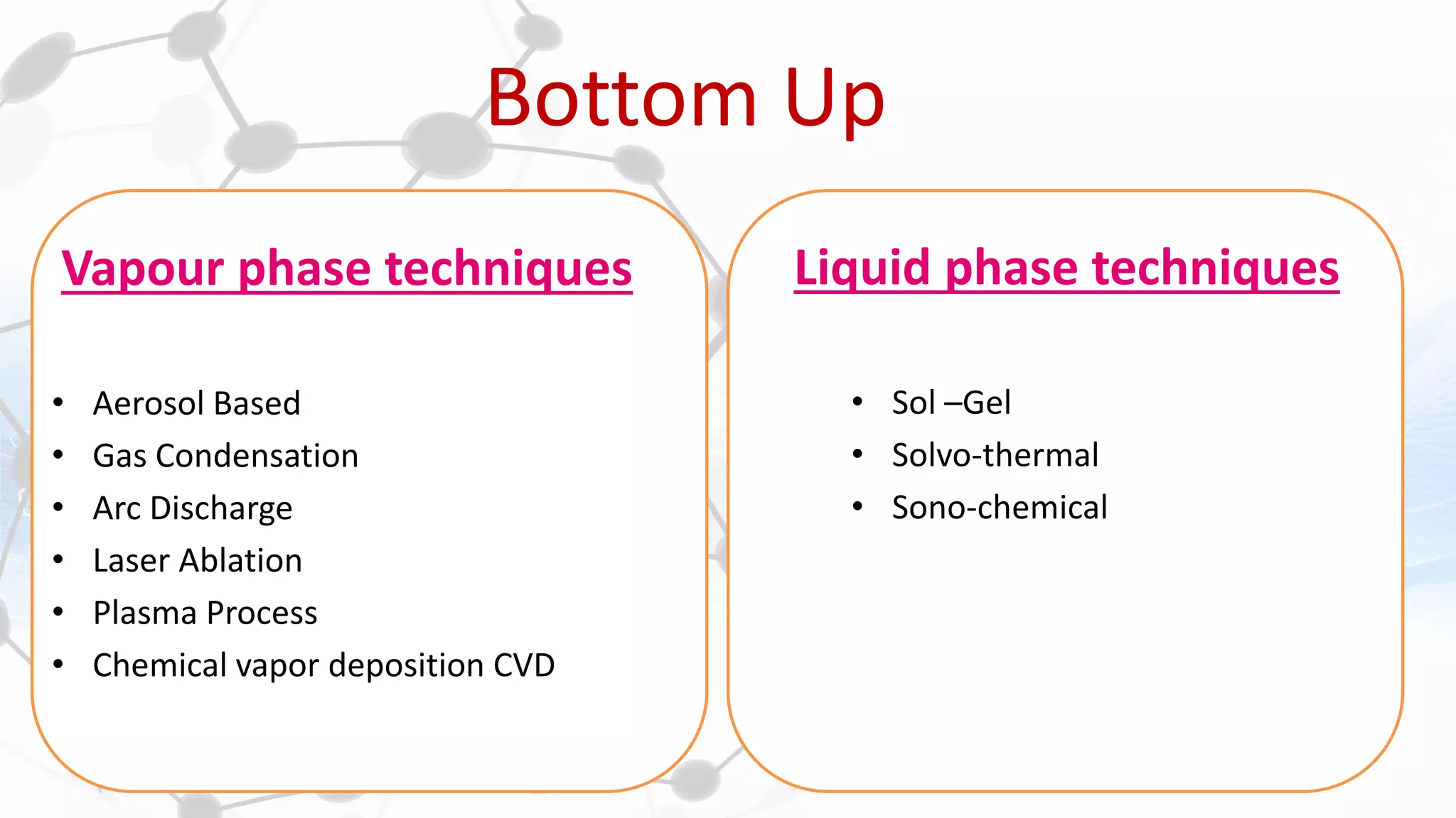

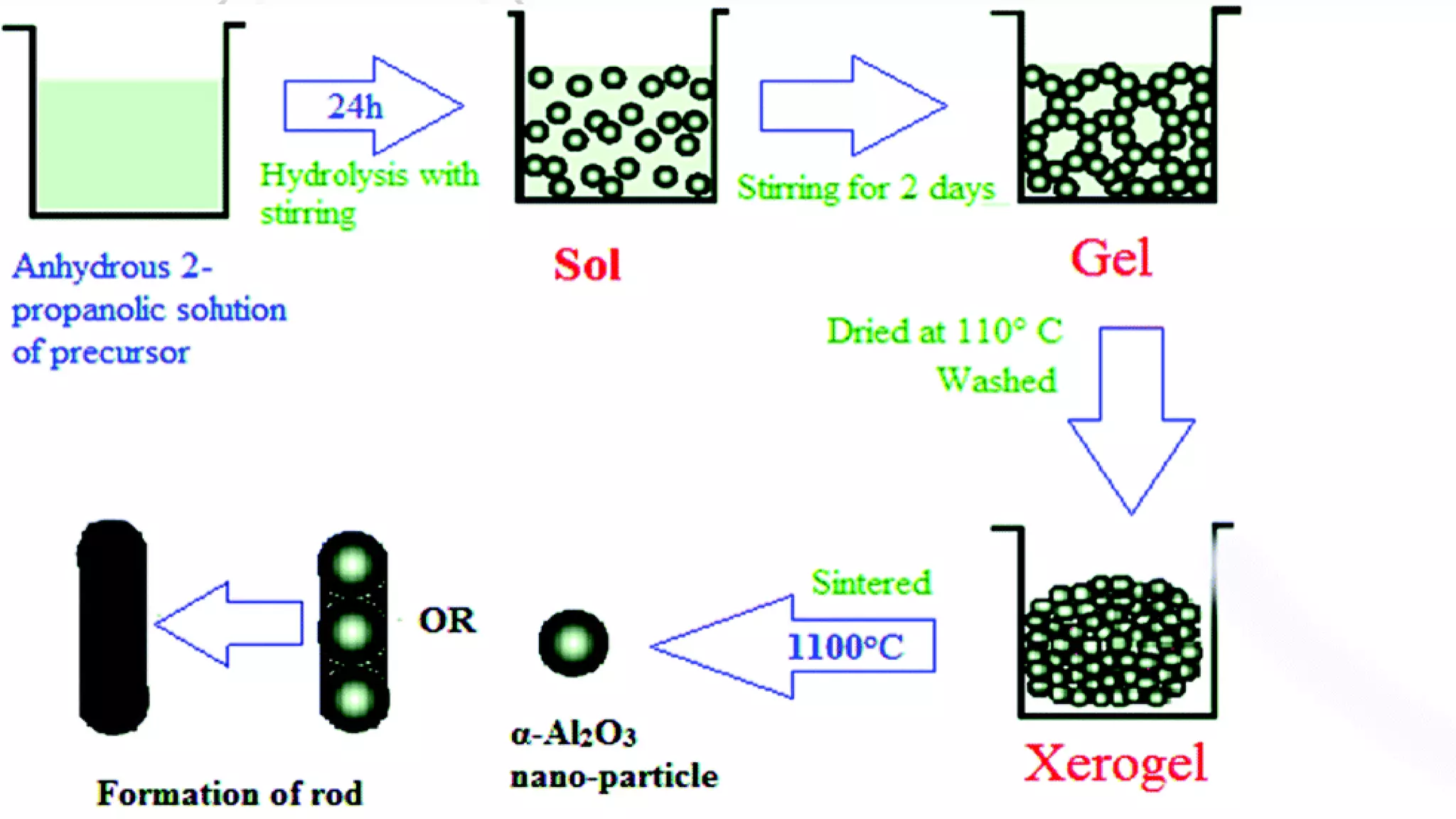

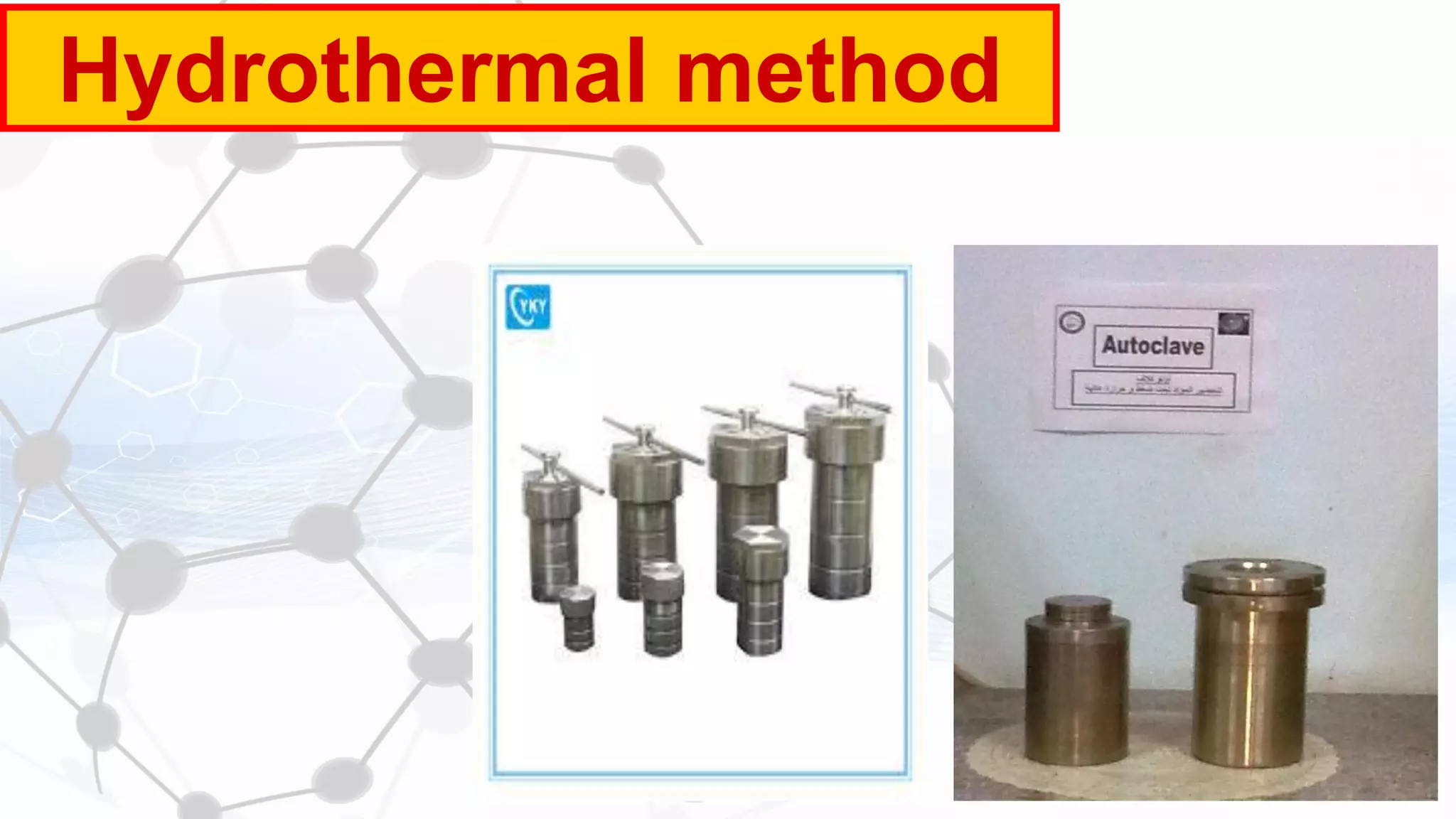


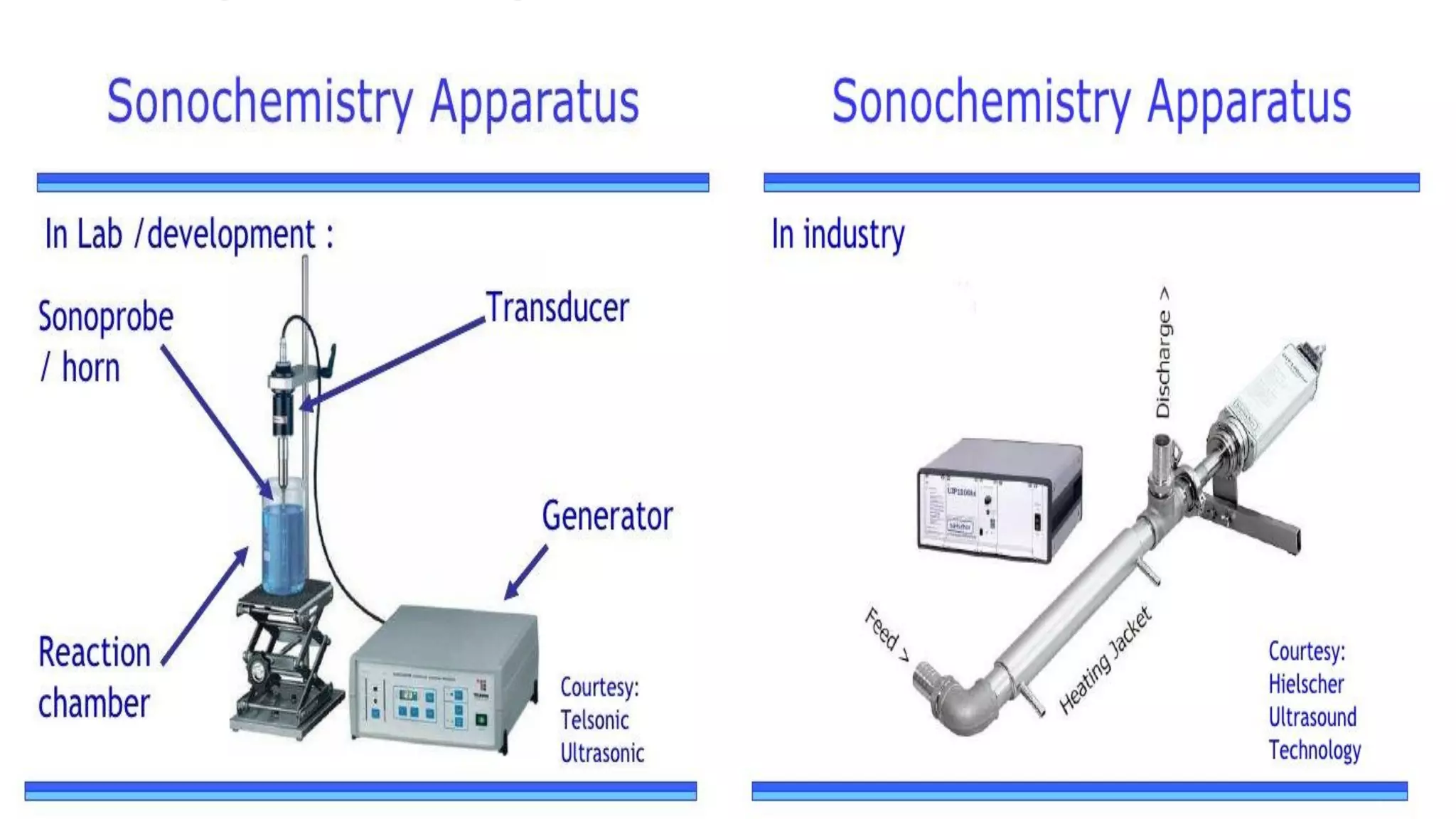

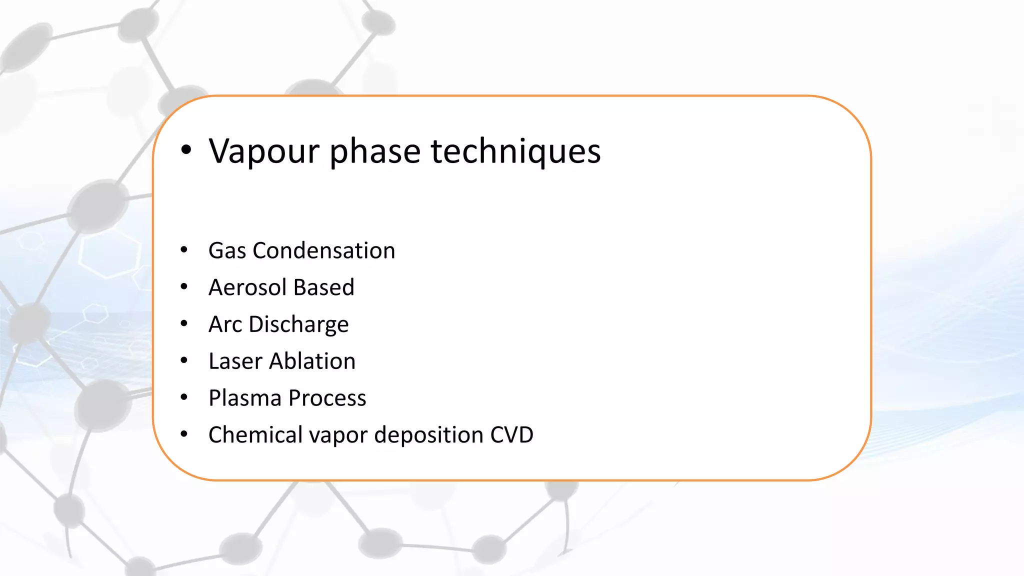

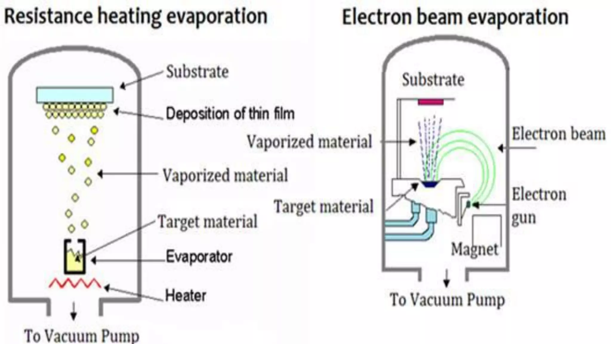


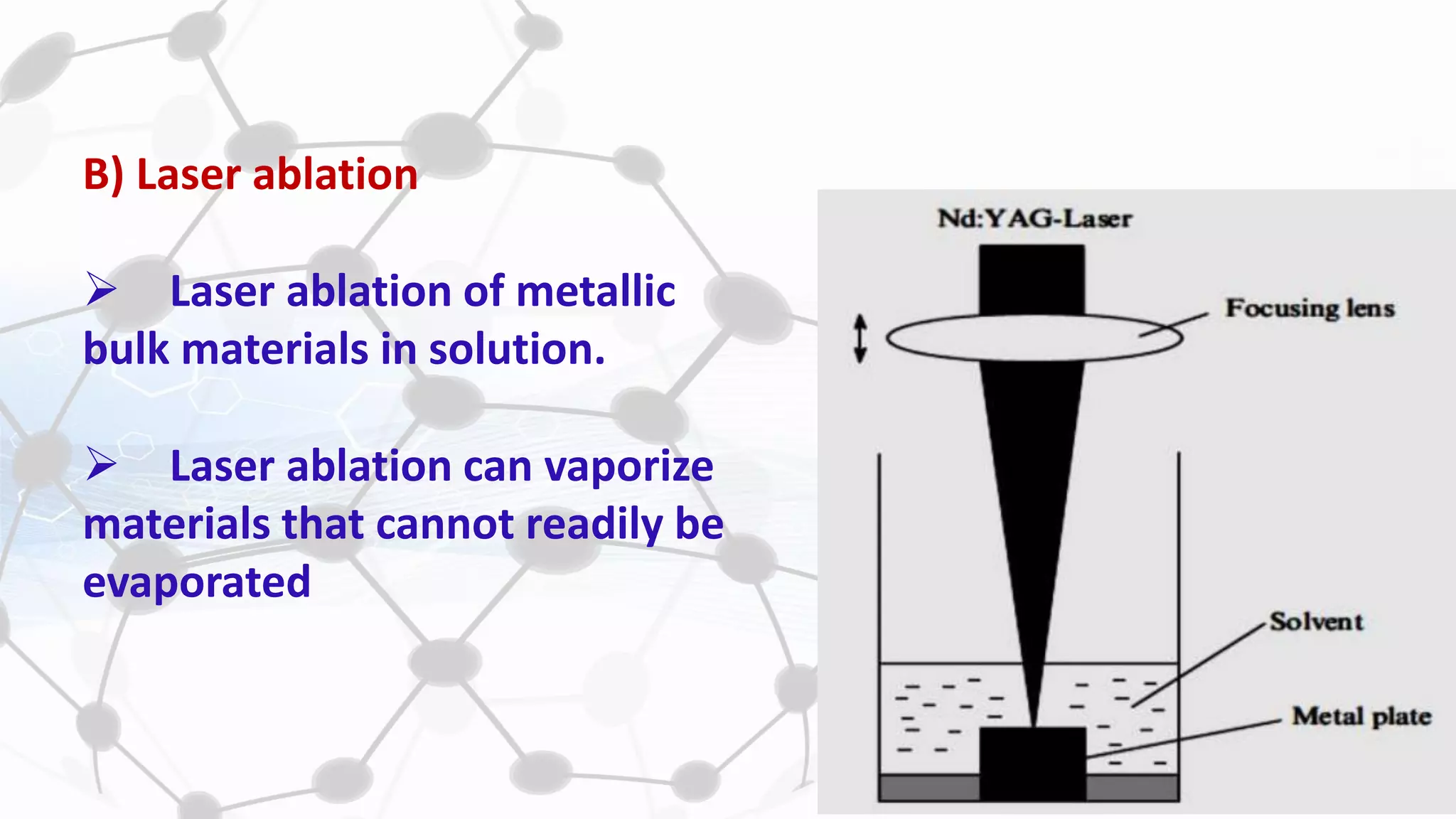


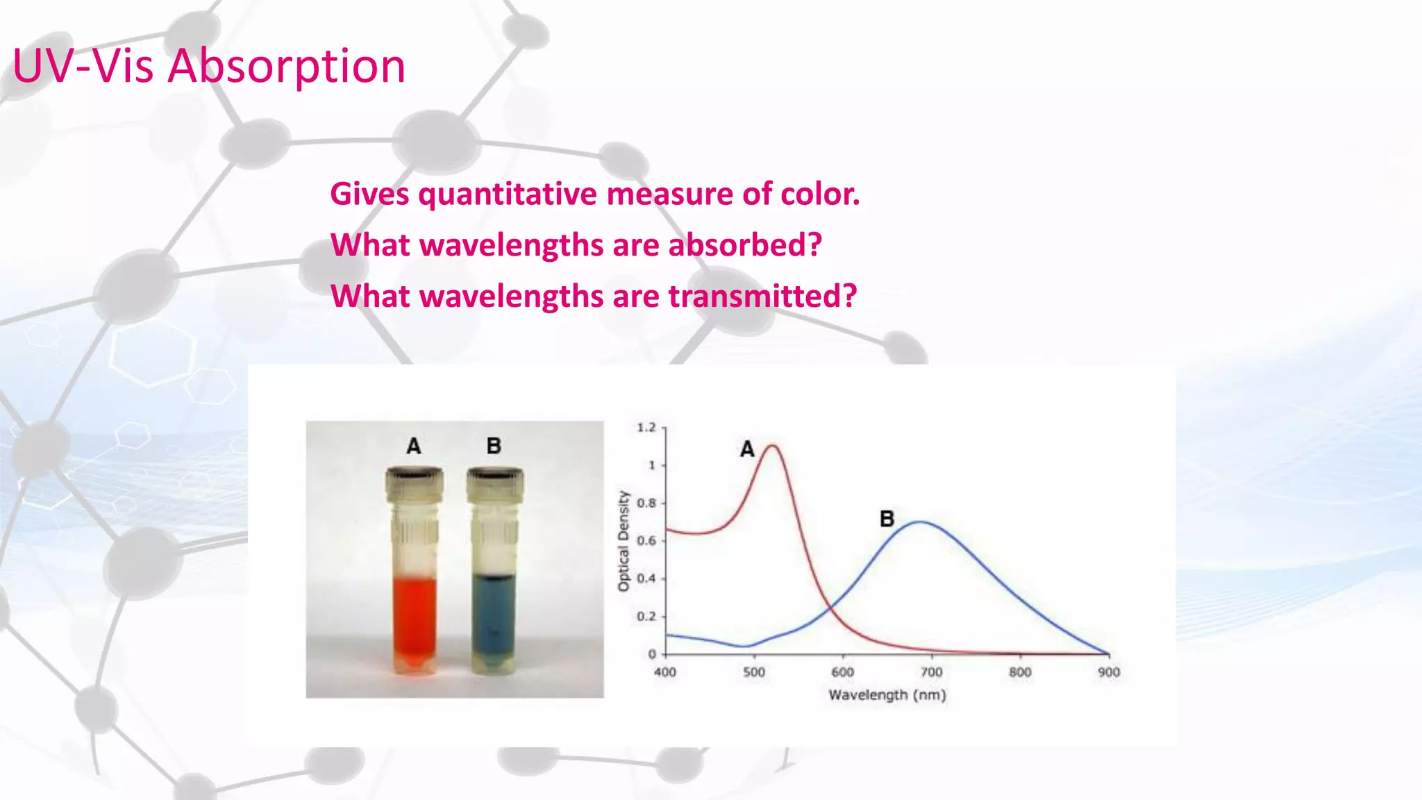
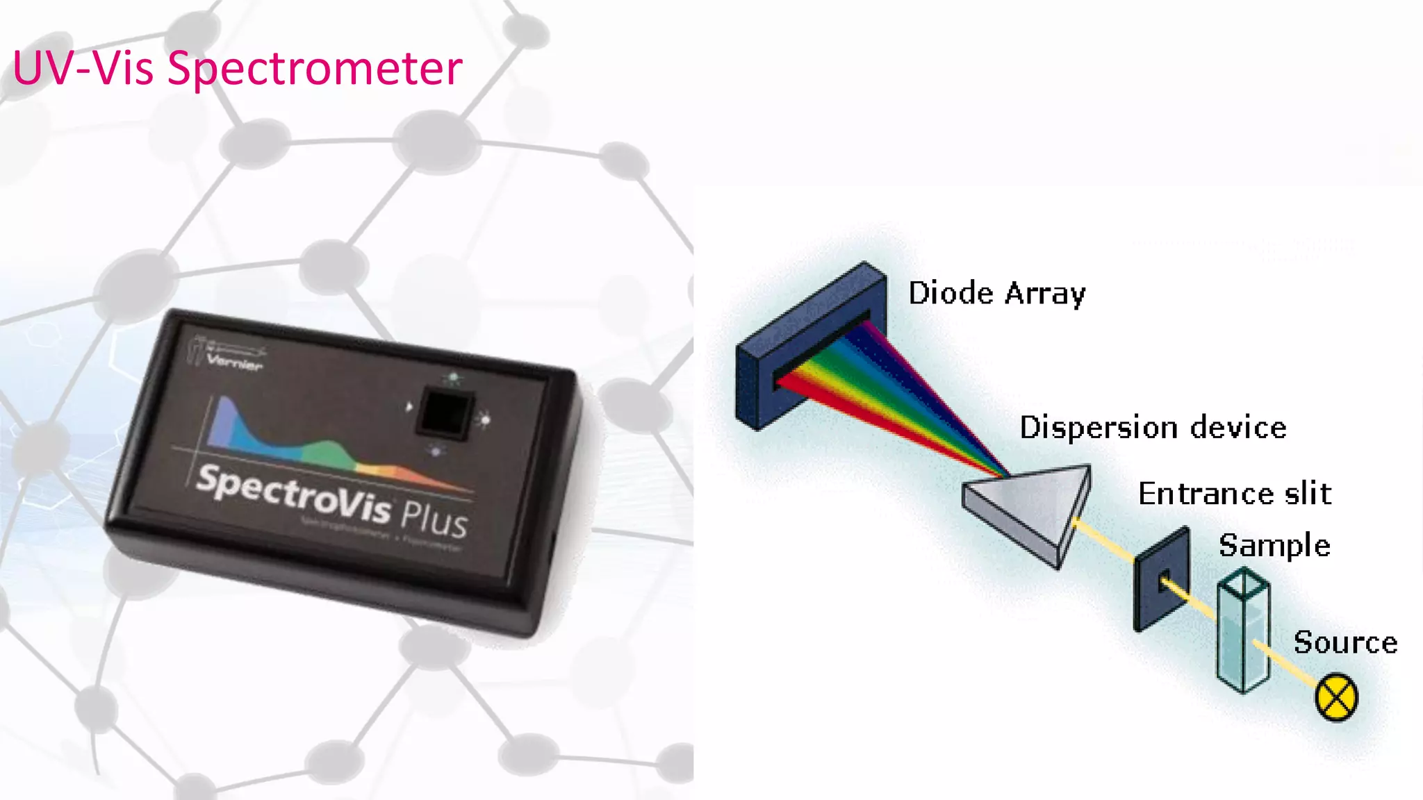


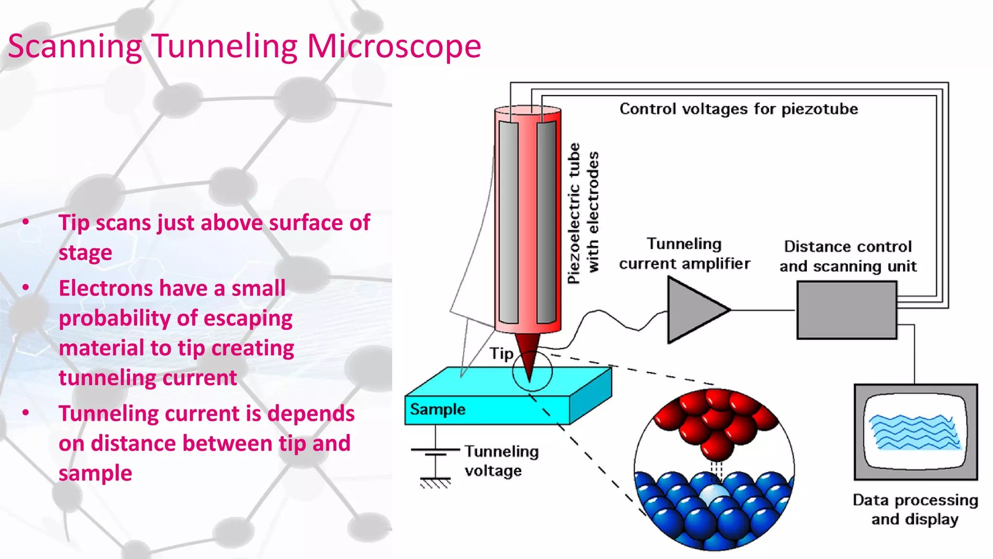


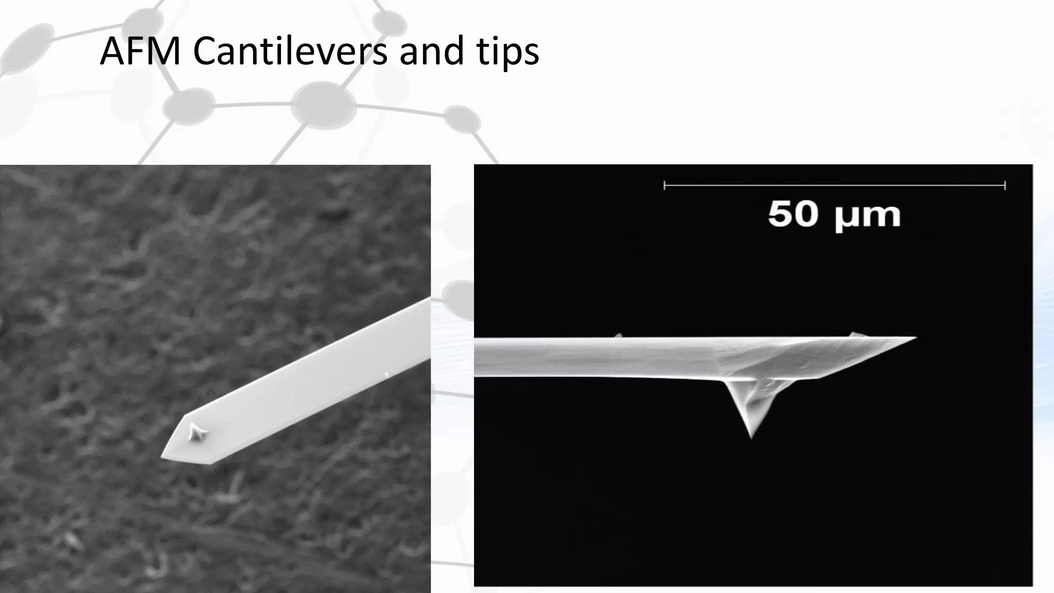


Nanoscience and nanotechnology involve working at the nanoscale level of 1 to 100 nanometers. The document discusses various methods for producing and characterizing nanoparticles and nanofluids. Top-down methods break down bulk materials into nanoparticles using techniques like ball milling, while bottom-up methods build nanoparticles from smaller units using approaches such as sol-gel synthesis and laser ablation. Characterization techniques discussed include UV-Vis spectroscopy, dynamic light scattering, transmission electron microscopy, and atomic force microscopy.


