Download to read offline


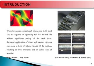
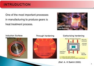
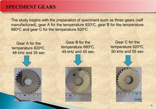
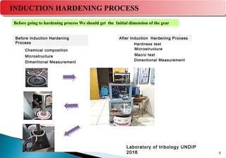
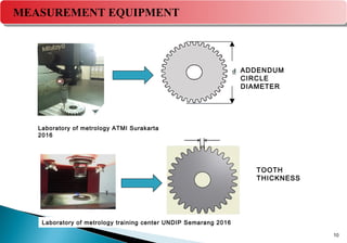
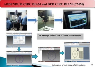
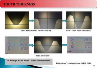
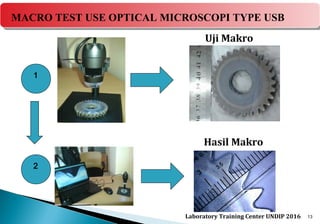
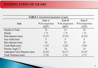
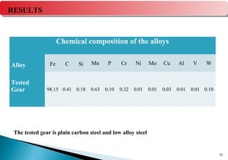
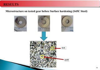
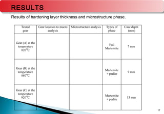
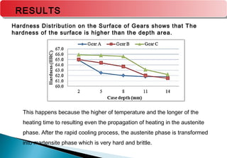
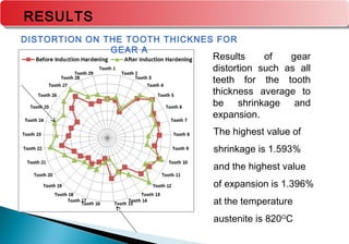
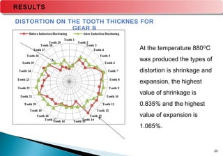
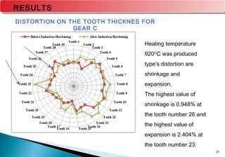
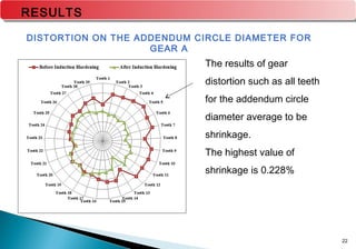
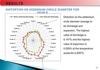
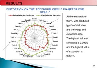
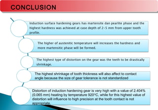


The document discusses research on the effect of temperature on distortion during induction surface hardening of gears. Three gears were induction hardened at different temperatures (820°C, 880°C, 920°C) and analyzed. Distortion was measured on tooth thickness and addendum circle diameter. The highest distortion values were 2.404% shrinkage on tooth thickness for the 920°C gear and 0.284% expansion on addendum circle for the same gear. Microstructure analysis found deeper martensite case depths with increasing temperature. Hardness also increased with depth from the surface.