Download to read offline

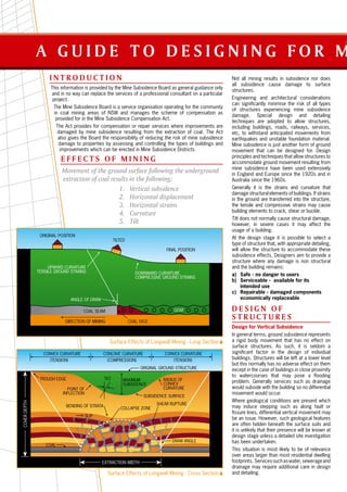


This document provides guidance on designing structures to withstand mine subsidence effects such as vertical subsidence, horizontal displacement, horizontal strains, curvature, and tilt. It discusses design considerations for each effect and recommends techniques like slip layers between foundations and soil to reduce strain transfer. The goal is to design structures that remain safe, serviceable, and economically repairable if damaged by subsidence. Approval must be obtained from the Mine Subsidence Board for any building work conducted in mine subsidence districts.