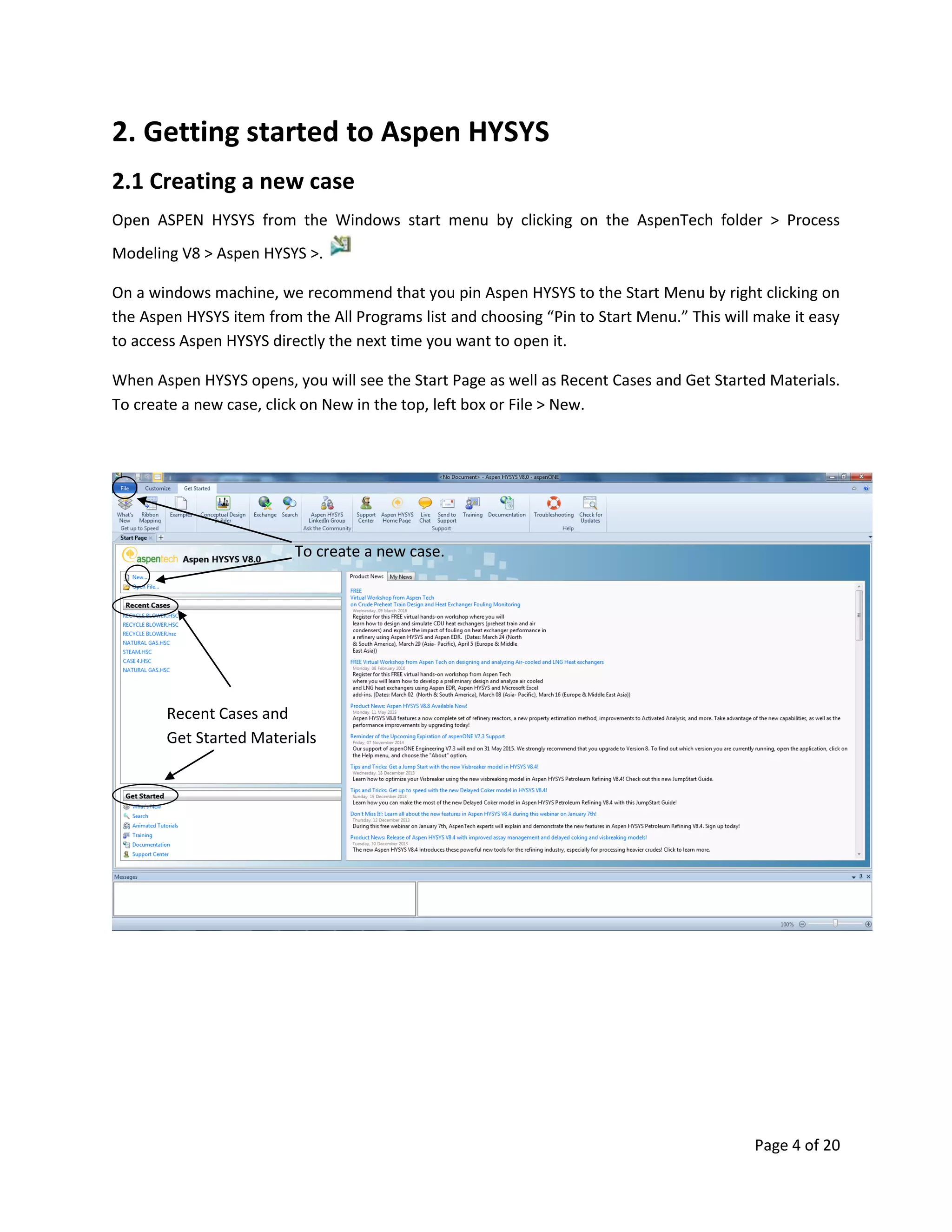
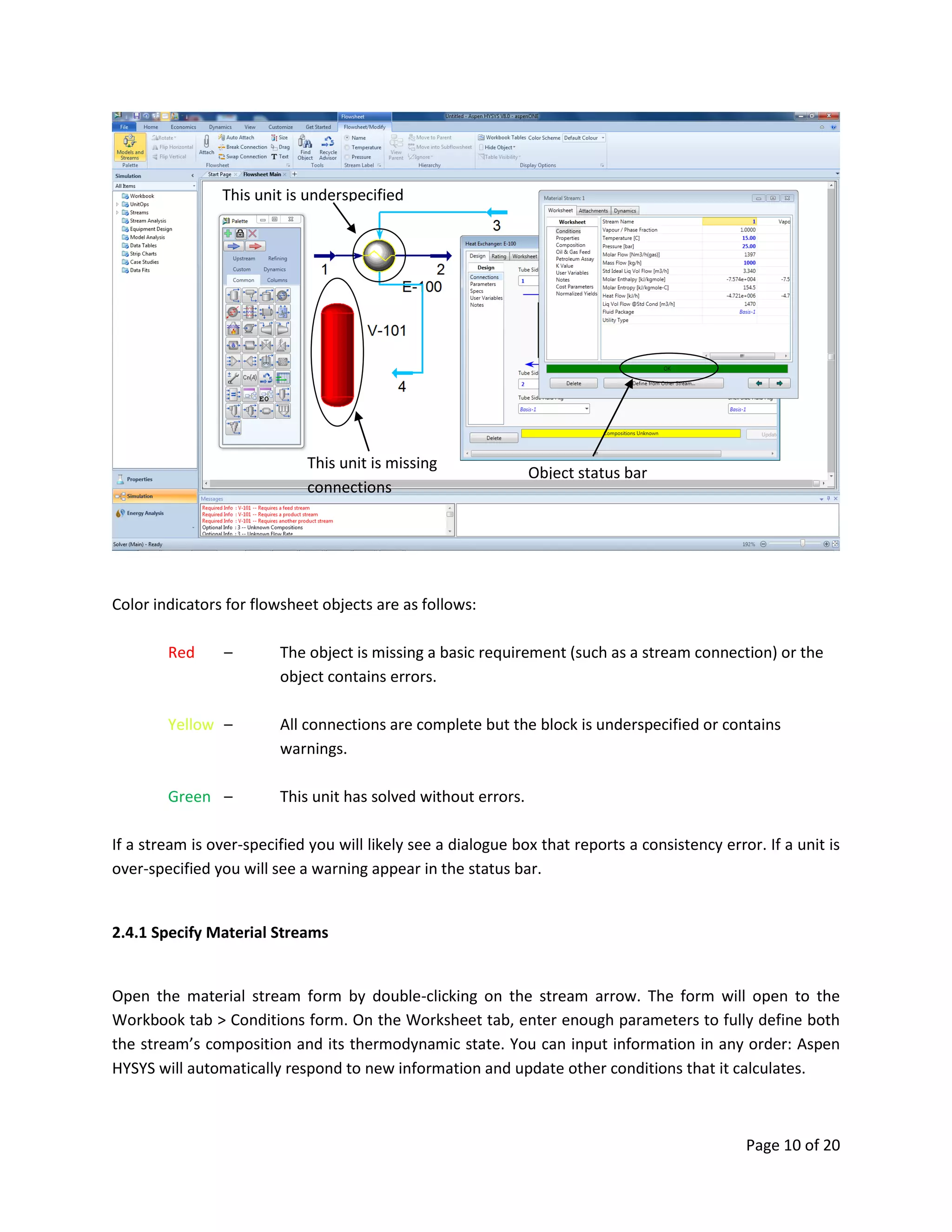
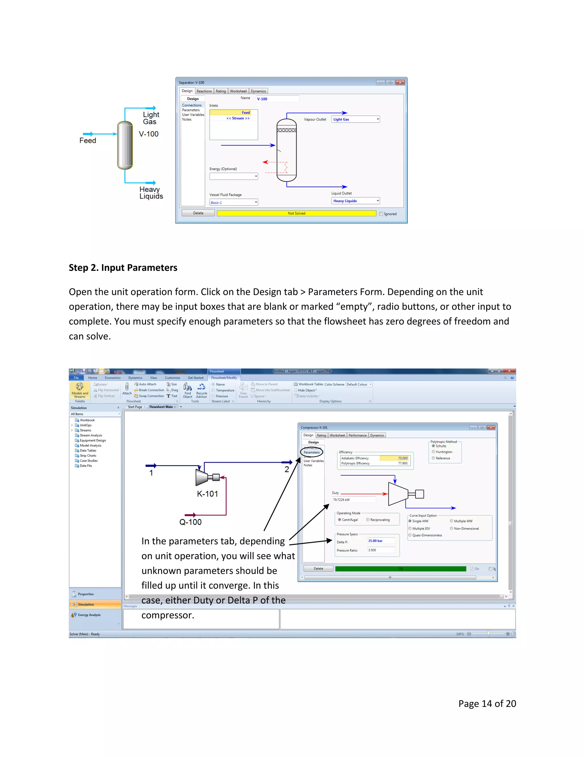
Page 1 of 20
HANDY MANUAL
Program “Aspen
HYSYS”
(Version 8.0)
Issue : May. - 2016
Status : For Process Department Internal Use Only
Prepared by : Baijan Savalan
Document No:
XXXXXXXXXXX
Page 2 of 20
Table of Contents
1. Introduction ..............................................................................................................................................3
2. Getting started to Aspen HYSYS................................................................................................................4
2.1 Creating a new case ............................................................................................................................4
2.2 Properties Environment......................................................................................................................5
2.2.1 Creating a Component List...........................................................................................................5
2.2.2 Selecting a Fluid Package .............................................................................................................6
2.3 The Simulation Environment ..............................................................................................................8
2.3.1 Adding Flowsheet Objects: The Model Palette............................................................................8
2.3.2 Add an Object from the Palette to the Flowsheet.......................................................................9
2.4 Specifying Flowsheet Objects .............................................................................................................9
2.4.1 Specify Material Streams ...........................................................................................................10
2.4.2 Specify Composition Manually...................................................................................................11
2.4.3 Define from Other Stream .........................................................................................................12
2.5 Specify Unit Operations ....................................................................................................................13
2.6 Flowsheet Controls ...........................................................................................................................15
Page 3 of 20
1. Introduction
Aspen HYSYS is a comprehensive process modeling tool used by the world’s leading oil and gas
producers, refineries, and engineering companies for process simulation and process optimization in
design and operations.
It is easy-to-use oil and gas process simulation software that enables optimization of conceptual design
and operations. Aspen HYSYS has an extensive array of unit operations, specialized work environments,
and with features and functionalities that address the process engineering challenges of the energy
industry.
This document is intended as a simple starting guide. It will cover the process of creating a new case,
setting up component list and fluid packages, and working in the simulation environment to build the
model.
Page 4 of 20
2. Getting started to Aspen HYSYS
2.1 Creating a new case
Open ASPEN HYSYS from the Windows start menu by clicking on the AspenTech folder > Process
Modeling V8 > Aspen HYSYS >.
On a windows machine, we recommend that you pin Aspen HYSYS to the Start Menu by right clicking on
the Aspen HYSYS item from the All Programs list and choosing “Pin to Start Menu.” This will make it easy
to access Aspen HYSYS directly the next time you want to open it.
When Aspen HYSYS opens, you will see the Start Page as well as Recent Cases and Get Started Materials.
To create a new case, click on New in the top, left box or File > New.
To create a new case.
Recent Cases and
Get Started Materials
Page 5 of 20
2.2 Properties Environment
All new cases start in the Properties environment. This is where you will select the components to be
used in your model and set the calculation methods for physical properties (fluid package). The
combination of a component list and a fluid package is called a property package. You cannot enter the
Simulation environment until at least one property package has been created and, if you have multiple
component lists, each one has been assigned a fluid package.
2.2.1 Creating a Component List
The first step to building a model is to create Component List which collectively contains all of the
components that will be used in your process. Later, when you specify a stream in the simulation
environment, you will need to choose a component list for that stream. It may be helpful to create
multiple component list in cases where streams have very different compositions.
Aspen HYSYS supports components both from its own databank and Aspen Properties.
To create an Aspen HYSYS component list, click on the Add Button at the bottom of the grid. To create
an Aspen Properties component list, click on the dropdown arrow and choose “Aspen Properties”.
From the Component List Section, click
Add to create components based on
your requirements.
Page 6 of 20
Now, use the search form to select which type of components to add to the list. When you type in the
“Search For” box, Aspen HYSYS will automatically populate matches in the grid below. Hitting ‘Enter’ or
clicking ‘Add’ will add the selected component to the list. You can use the shift and control keys to add
multiple components at a time and you can reorder the list by dragging and dropping cells.
2.2.2 Selecting a Fluid Package
You must associate each component list with a Fluid Package. Click on the Fluid Packages folder in the
navigation pane or on the Fluid Package icon from the Home ribbon.
Click on the Add button to add an Aspen HYSYS fluid package. Next, click on the dropdown arrow for the
additional options of Aspen Properties And COMThermo.
By default the fluid package created will be of the Aspen HYSYS type. Use the Selection dropdown box to
choose another list. In the Property Package Selection box, click on the fluid package that you want to
use to complete this property package setup.
Search Box
List of
components
to be used.
Search Result
/ Library of
components
Page 7 of 20
From the Fluid Package Section, click
Add to include fluid property package
based on your requirements.
You can select here fluid package
suitable for the components that you
have provided.
If you are unsure what fluid
package to be used then click
this Methods Assistant. It will
guide you to choose the correct
fluid package.
Page 8 of 20
2.3 The Simulation Environment
With property packages specified, you are now ready to begin creating your model. Click on the
Simulation environment button on the bottom left panel.
You will see the object palette appear on top of a blank flowsheet. You can start by adding either a
material stream or a unit operation from the palette.
2.3.1 Adding Flowsheet Objects: The Model Palette
Unit operations on the model palette are organized into six tabs, the most frequently used operations
are located on the “Common” tab. There are also tabs for refining, dynamics, columns, upstream, and
custom.
Material streams can be added using the blue arrow and energy streams can be added using the red
arrow. If you close the palette you can re-open it from the View Ribbon, Flowsheet/Modify Ribbon, or by
using the F4 keyboard shortcut.
After completing the components list
and fluid packages, click simulation
environment to start creating streams
and unit operations.
This is the object palette which shows
the different icons including material
streams and unit operation to use for
creating the simulation. Press F4 for
shortcut.
Page 9 of 20
2.3.2 Add an Object from the Palette to the Flowsheet
To place a unit or material stream on the flowsheet, click the icon in the palette and move the mouse
over the flowsheet to where you would like to place the object. You will see that the mouse has a plus
sign next to it, indicating that when you click the mouse again, the object will be added.
2.4 Specifying Flowsheet Objects
The Aspen HYSYS solver is uniquely flexible and very robust; when the solver is active, it automatically
responds to input entered for any object in the flowsheet and back calculates the parameter for the
entire process. Visual indicators display the status of all flowsheet objects. You can see the status of an
object both on the flowsheet itself and on the status bar at the bottom of an object form.
Add a material stream Add an energy stream
User defined models and
extensions
Separator Columns
and Reactors.
Page 10 of 20
Color indicators for flowsheet objects are as follows:
Red – The object is missing a basic requirement (such as a stream connection) or the
object contains errors.
Yellow – All connections are complete but the block is underspecified or contains
warnings.
Green – This unit has solved without errors.
If a stream is over-specified you will likely see a dialogue box that reports a consistency error. If a unit is
over-specified you will see a warning appear in the status bar.
2.4.1 Specify Material Streams
Open the material stream form by double-clicking on the stream arrow. The form will open to the
Workbook tab > Conditions form. On the Worksheet tab, enter enough parameters to fully define both
the stream’s composition and its thermodynamic state. You can input information in any order: Aspen
HYSYS will automatically respond to new information and update other conditions that it calculates.
This unit is missing
connections
This unit is underspecified
Object status bar
Page 11 of 20
2.4.2 Specify Composition Manually
Click on the Composition form in the Worksheet list. Type a value into any cell and the Input
Composition form will appear. On the right, you can select which unit of data to enter and on the
bottom you can use the controls to erase or normalize values entered. Type the values for each
component in the cell next to their names.
Fill up at least up
to 3 process
condition.
Page 12 of 20
2.4.3 Define from Other Stream
You also have the option to define a stream’s condition from another stream. Click the “Define from
other stream” button on the stream form to enable this. Choose which stream to copy in the Available
Stream box. You can transfer all data from another stream or choose specific information to copy.
And fill up also stream
composition manually
to converge
Page 13 of 20
2.5 Specify Unit Operations
Double click on any unit to open the form. You will see that the status indicator, as well as the object
itself, is red. Add connections for input and output on the Design > Connections tab. Then move to the
Design > Parameters tab to specify size, pressure drop, duty, and whatever else is required for that
particular unit. See below for more details.
Step 1. Add Connections
a) Add Connections using the unit operation Form.
Click inside the Inlet grid and type the name of the inlet stream. Repeat for Vapor and Liquid Outlets.
This is one way to create and connect a stream.
b) Add Connections on the Flowsheet.
Click the blue arrow on the palette to select it. Click on the flowsheet in the location you want to place
the stream. Deselect objects by clicking on a blank area of the flowsheet. Now, view attachment ports
by either holding down the control key or clicking the Attach icon on the Flowsheet/Modify ribbon. Click
on one of the ports, drag the mouse, and release over the inlet port of a unit operation or another
stream.
Click this to copy the stream from
the existing stream available.
Choose what stream to copy
As a default, it copies everything
from the stream. But you can
define what only needs to copy.
Page 14 of 20
Step 2. Input Parameters
Open the unit operation form. Click on the Design tab > Parameters Form. Depending on the unit
operation, there may be input boxes that are blank or marked “empty”, radio buttons, or other input to
complete. You must specify enough parameters so that the flowsheet has zero degrees of freedom and
can solve.
In the parameters tab, depending
on unit operation, you will see what
unknown parameters should be
filled up until it converge. In this
case, either Duty or Delta P of the
compressor.
Page 15 of 20
2.6 Flowsheet Controls
While you are building your flowsheet, you may find it helpful to use the controls provided on the
Flowsheet/Modify ribbon and the right-mouse-button menu of flowsheet objects. We will cover some of
the most commonly used functions here.
a) Attach Mode
Using attach mode is the equivalent to holding down the control key; all available object ports will be
displayed as you move the mouse on the flowsheet.
b) Auto Attach
When auto is selected, you can do the following:
(1) Make sure all other objects are deselected and add a unit operation. When the operation is
added to the flowsheet, new streams will be defined for the input and output of that object;
(2) Before adding your unit, select a stream or object that you would like connected to it. The
stream will automatically be connected as the input to that operation. For a connected object, a
dialogue box will appear asking which stream from the first object you would like to connect to
the newly added one. This is particularly useful if you have many streams as the input to a new
object, such as a mixer.
Page 16 of 20
c) Find Object
The Find Object button, located in the Tools group of the Flowsheet/Modify tab, can be used both to
locate any object on a large flowsheet and to directly open any object form. Click on the icon from the
Flowsheet ribbon to open the Object Navigator.
The choices on the Object Navigator are as follows:
(1) Find – Open the form for any object or group of objects. For single objects, type in the full
object name. For a group of objects, type an asterisk, a common character, and another asterisk.
For instance, to open the forms for all exchangers with a number in the 300’s, click Find and
type *e3*.
(2) View – Open the form for the selected object in the Unit Operations List.
(3) Locate – Navigate to the selected Unit Operation in the flowsheet. This command will move
the flowsheet within the visible area to the location of the selected object.
d) Flowsheet Hierarchy
In large complex flowsheets, it is often useful to organize processes into smaller stages. In this case,
blocks represents a particular group of operations. When creating a block, highlight unit operations that
you want to include then right-click and choose “Combine into Sub-Flowsheet”, and it will create block
automatically. If you double-click on any of these blocks you will be able to enter the sub-flowsheet
environment using a button of the form. You can also right-click on the block and use the “Open sub
flowsheet as new tab” selection. Inside the sub flowsheet you will see only objects related to that
particular part of the process. If any changes are made in this environment they will not be passed to
Page 17 of 20
the main flowsheet until you navigate back to the parent – this may cause some objects in the sub
flowsheets to be temporarily unsolved. Use the “View Parent” Ribbon button to navigate back to the
main flowsheet.
e) Display Options
Use the features in this category to change the color schemes for the process flowsheet and workbook
tables and to hide or display objects and tables.
Page 18 of 20
f) The flowsheet Right-Mouse-Button (RMB) Menu
The right-mouse click menu allows you to perform all of the standard commands for objects such as cut,
copy, paste, and delete. It also contains a number of extended functions such as Import/Export, open a
form as a new tab, and change the operation’s icon.
g) Setting Preferences
To set preferences, open the File menu and click on “Options” in the bottom right corner. Some of the
useful tools to use here are changing the “Units of Measure” and using “Allow multiple stream
connection”.
Page 19 of 20
3. OPTIMIZATION
3.1 Utility Analysis
To view the utility analysis of a stream, double click the stream, and chose the “Attachments” tab, then
select the Analysis. Click the Create button to create a phase envelope for the stream. The Available
Stream Analysis view appears, displaying a list of HYSYS utilities.
List of Utility Analysis for additional helpful information:
a) Boiling Point Curves - Obtain laboratory-style distillation results for streams;
b) CO2 Freeze Out - Determine stream CO2 freezing conditions;
c) Cold Properties - Calculate several stream Cold Properties (e.g. True and Reid
Vapor Pressures, Flash Point, Pour Point, Refractive Index, etc.);
d) Critical Properties - Calculate true and pseudo critical properties for streams.
e) Envelope - Show critical values and phase diagrams for a stream;
f) Hydrate Formation - Determine stream hydrate formation conditions;
g) Petroleum Assay - New features in Aspen HYSYS allow users to utilize the same
assay library and tools previously only available to Aspen PIMS
users. The new features make access an extensive database of
crudes and crude properties with new assay library and easily
import data from other sources;
h) Pipe Sizing - Determine pressure drop or line sizing based on flowrate;
i) Property Table - Examine stream property trends over a range of conditions; and
j) User Property - Define new stream properties based on composition.
Page 20 of 20
Click create to choose what stream
analysis you want.
Double click stream and click
attachments and then Analysis.

Baijan Savalan Hysys v8.0

  • 1.
    Page 1 of20 HANDY MANUAL Program “Aspen HYSYS” (Version 8.0) Issue : May. - 2016 Status : For Process Department Internal Use Only Prepared by : Baijan Savalan Document No: XXXXXXXXXXX
  • 2.
    Page 2 of20 Table of Contents 1. Introduction ..............................................................................................................................................3 2. Getting started to Aspen HYSYS................................................................................................................4 2.1 Creating a new case ............................................................................................................................4 2.2 Properties Environment......................................................................................................................5 2.2.1 Creating a Component List...........................................................................................................5 2.2.2 Selecting a Fluid Package .............................................................................................................6 2.3 The Simulation Environment ..............................................................................................................8 2.3.1 Adding Flowsheet Objects: The Model Palette............................................................................8 2.3.2 Add an Object from the Palette to the Flowsheet.......................................................................9 2.4 Specifying Flowsheet Objects .............................................................................................................9 2.4.1 Specify Material Streams ...........................................................................................................10 2.4.2 Specify Composition Manually...................................................................................................11 2.4.3 Define from Other Stream .........................................................................................................12 2.5 Specify Unit Operations ....................................................................................................................13 2.6 Flowsheet Controls ...........................................................................................................................15
  • 3.
    Page 3 of20 1. Introduction Aspen HYSYS is a comprehensive process modeling tool used by the world’s leading oil and gas producers, refineries, and engineering companies for process simulation and process optimization in design and operations. It is easy-to-use oil and gas process simulation software that enables optimization of conceptual design and operations. Aspen HYSYS has an extensive array of unit operations, specialized work environments, and with features and functionalities that address the process engineering challenges of the energy industry. This document is intended as a simple starting guide. It will cover the process of creating a new case, setting up component list and fluid packages, and working in the simulation environment to build the model.
  • 4.
    Page 4 of20 2. Getting started to Aspen HYSYS 2.1 Creating a new case Open ASPEN HYSYS from the Windows start menu by clicking on the AspenTech folder > Process Modeling V8 > Aspen HYSYS >. On a windows machine, we recommend that you pin Aspen HYSYS to the Start Menu by right clicking on the Aspen HYSYS item from the All Programs list and choosing “Pin to Start Menu.” This will make it easy to access Aspen HYSYS directly the next time you want to open it. When Aspen HYSYS opens, you will see the Start Page as well as Recent Cases and Get Started Materials. To create a new case, click on New in the top, left box or File > New. To create a new case. Recent Cases and Get Started Materials
  • 5.
    Page 5 of20 2.2 Properties Environment All new cases start in the Properties environment. This is where you will select the components to be used in your model and set the calculation methods for physical properties (fluid package). The combination of a component list and a fluid package is called a property package. You cannot enter the Simulation environment until at least one property package has been created and, if you have multiple component lists, each one has been assigned a fluid package. 2.2.1 Creating a Component List The first step to building a model is to create Component List which collectively contains all of the components that will be used in your process. Later, when you specify a stream in the simulation environment, you will need to choose a component list for that stream. It may be helpful to create multiple component list in cases where streams have very different compositions. Aspen HYSYS supports components both from its own databank and Aspen Properties. To create an Aspen HYSYS component list, click on the Add Button at the bottom of the grid. To create an Aspen Properties component list, click on the dropdown arrow and choose “Aspen Properties”. From the Component List Section, click Add to create components based on your requirements.
  • 6.
    Page 6 of20 Now, use the search form to select which type of components to add to the list. When you type in the “Search For” box, Aspen HYSYS will automatically populate matches in the grid below. Hitting ‘Enter’ or clicking ‘Add’ will add the selected component to the list. You can use the shift and control keys to add multiple components at a time and you can reorder the list by dragging and dropping cells. 2.2.2 Selecting a Fluid Package You must associate each component list with a Fluid Package. Click on the Fluid Packages folder in the navigation pane or on the Fluid Package icon from the Home ribbon. Click on the Add button to add an Aspen HYSYS fluid package. Next, click on the dropdown arrow for the additional options of Aspen Properties And COMThermo. By default the fluid package created will be of the Aspen HYSYS type. Use the Selection dropdown box to choose another list. In the Property Package Selection box, click on the fluid package that you want to use to complete this property package setup. Search Box List of components to be used. Search Result / Library of components
  • 7.
    Page 7 of20 From the Fluid Package Section, click Add to include fluid property package based on your requirements. You can select here fluid package suitable for the components that you have provided. If you are unsure what fluid package to be used then click this Methods Assistant. It will guide you to choose the correct fluid package.
  • 8.
    Page 8 of20 2.3 The Simulation Environment With property packages specified, you are now ready to begin creating your model. Click on the Simulation environment button on the bottom left panel. You will see the object palette appear on top of a blank flowsheet. You can start by adding either a material stream or a unit operation from the palette. 2.3.1 Adding Flowsheet Objects: The Model Palette Unit operations on the model palette are organized into six tabs, the most frequently used operations are located on the “Common” tab. There are also tabs for refining, dynamics, columns, upstream, and custom. Material streams can be added using the blue arrow and energy streams can be added using the red arrow. If you close the palette you can re-open it from the View Ribbon, Flowsheet/Modify Ribbon, or by using the F4 keyboard shortcut. After completing the components list and fluid packages, click simulation environment to start creating streams and unit operations. This is the object palette which shows the different icons including material streams and unit operation to use for creating the simulation. Press F4 for shortcut.
  • 9.
    Page 9 of20 2.3.2 Add an Object from the Palette to the Flowsheet To place a unit or material stream on the flowsheet, click the icon in the palette and move the mouse over the flowsheet to where you would like to place the object. You will see that the mouse has a plus sign next to it, indicating that when you click the mouse again, the object will be added. 2.4 Specifying Flowsheet Objects The Aspen HYSYS solver is uniquely flexible and very robust; when the solver is active, it automatically responds to input entered for any object in the flowsheet and back calculates the parameter for the entire process. Visual indicators display the status of all flowsheet objects. You can see the status of an object both on the flowsheet itself and on the status bar at the bottom of an object form. Add a material stream Add an energy stream User defined models and extensions Separator Columns and Reactors.
  • 10.
    Page 10 of20 Color indicators for flowsheet objects are as follows: Red – The object is missing a basic requirement (such as a stream connection) or the object contains errors. Yellow – All connections are complete but the block is underspecified or contains warnings. Green – This unit has solved without errors. If a stream is over-specified you will likely see a dialogue box that reports a consistency error. If a unit is over-specified you will see a warning appear in the status bar. 2.4.1 Specify Material Streams Open the material stream form by double-clicking on the stream arrow. The form will open to the Workbook tab > Conditions form. On the Worksheet tab, enter enough parameters to fully define both the stream’s composition and its thermodynamic state. You can input information in any order: Aspen HYSYS will automatically respond to new information and update other conditions that it calculates. This unit is missing connections This unit is underspecified Object status bar
  • 11.
    Page 11 of20 2.4.2 Specify Composition Manually Click on the Composition form in the Worksheet list. Type a value into any cell and the Input Composition form will appear. On the right, you can select which unit of data to enter and on the bottom you can use the controls to erase or normalize values entered. Type the values for each component in the cell next to their names. Fill up at least up to 3 process condition.
  • 12.
    Page 12 of20 2.4.3 Define from Other Stream You also have the option to define a stream’s condition from another stream. Click the “Define from other stream” button on the stream form to enable this. Choose which stream to copy in the Available Stream box. You can transfer all data from another stream or choose specific information to copy. And fill up also stream composition manually to converge
  • 13.
    Page 13 of20 2.5 Specify Unit Operations Double click on any unit to open the form. You will see that the status indicator, as well as the object itself, is red. Add connections for input and output on the Design > Connections tab. Then move to the Design > Parameters tab to specify size, pressure drop, duty, and whatever else is required for that particular unit. See below for more details. Step 1. Add Connections a) Add Connections using the unit operation Form. Click inside the Inlet grid and type the name of the inlet stream. Repeat for Vapor and Liquid Outlets. This is one way to create and connect a stream. b) Add Connections on the Flowsheet. Click the blue arrow on the palette to select it. Click on the flowsheet in the location you want to place the stream. Deselect objects by clicking on a blank area of the flowsheet. Now, view attachment ports by either holding down the control key or clicking the Attach icon on the Flowsheet/Modify ribbon. Click on one of the ports, drag the mouse, and release over the inlet port of a unit operation or another stream. Click this to copy the stream from the existing stream available. Choose what stream to copy As a default, it copies everything from the stream. But you can define what only needs to copy.
  • 14.
    Page 14 of20 Step 2. Input Parameters Open the unit operation form. Click on the Design tab > Parameters Form. Depending on the unit operation, there may be input boxes that are blank or marked “empty”, radio buttons, or other input to complete. You must specify enough parameters so that the flowsheet has zero degrees of freedom and can solve. In the parameters tab, depending on unit operation, you will see what unknown parameters should be filled up until it converge. In this case, either Duty or Delta P of the compressor.
  • 15.
    Page 15 of20 2.6 Flowsheet Controls While you are building your flowsheet, you may find it helpful to use the controls provided on the Flowsheet/Modify ribbon and the right-mouse-button menu of flowsheet objects. We will cover some of the most commonly used functions here. a) Attach Mode Using attach mode is the equivalent to holding down the control key; all available object ports will be displayed as you move the mouse on the flowsheet. b) Auto Attach When auto is selected, you can do the following: (1) Make sure all other objects are deselected and add a unit operation. When the operation is added to the flowsheet, new streams will be defined for the input and output of that object; (2) Before adding your unit, select a stream or object that you would like connected to it. The stream will automatically be connected as the input to that operation. For a connected object, a dialogue box will appear asking which stream from the first object you would like to connect to the newly added one. This is particularly useful if you have many streams as the input to a new object, such as a mixer.
  • 16.
    Page 16 of20 c) Find Object The Find Object button, located in the Tools group of the Flowsheet/Modify tab, can be used both to locate any object on a large flowsheet and to directly open any object form. Click on the icon from the Flowsheet ribbon to open the Object Navigator. The choices on the Object Navigator are as follows: (1) Find – Open the form for any object or group of objects. For single objects, type in the full object name. For a group of objects, type an asterisk, a common character, and another asterisk. For instance, to open the forms for all exchangers with a number in the 300’s, click Find and type *e3*. (2) View – Open the form for the selected object in the Unit Operations List. (3) Locate – Navigate to the selected Unit Operation in the flowsheet. This command will move the flowsheet within the visible area to the location of the selected object. d) Flowsheet Hierarchy In large complex flowsheets, it is often useful to organize processes into smaller stages. In this case, blocks represents a particular group of operations. When creating a block, highlight unit operations that you want to include then right-click and choose “Combine into Sub-Flowsheet”, and it will create block automatically. If you double-click on any of these blocks you will be able to enter the sub-flowsheet environment using a button of the form. You can also right-click on the block and use the “Open sub flowsheet as new tab” selection. Inside the sub flowsheet you will see only objects related to that particular part of the process. If any changes are made in this environment they will not be passed to
  • 17.
    Page 17 of20 the main flowsheet until you navigate back to the parent – this may cause some objects in the sub flowsheets to be temporarily unsolved. Use the “View Parent” Ribbon button to navigate back to the main flowsheet. e) Display Options Use the features in this category to change the color schemes for the process flowsheet and workbook tables and to hide or display objects and tables.
  • 18.
    Page 18 of20 f) The flowsheet Right-Mouse-Button (RMB) Menu The right-mouse click menu allows you to perform all of the standard commands for objects such as cut, copy, paste, and delete. It also contains a number of extended functions such as Import/Export, open a form as a new tab, and change the operation’s icon. g) Setting Preferences To set preferences, open the File menu and click on “Options” in the bottom right corner. Some of the useful tools to use here are changing the “Units of Measure” and using “Allow multiple stream connection”.
  • 19.
    Page 19 of20 3. OPTIMIZATION 3.1 Utility Analysis To view the utility analysis of a stream, double click the stream, and chose the “Attachments” tab, then select the Analysis. Click the Create button to create a phase envelope for the stream. The Available Stream Analysis view appears, displaying a list of HYSYS utilities. List of Utility Analysis for additional helpful information: a) Boiling Point Curves - Obtain laboratory-style distillation results for streams; b) CO2 Freeze Out - Determine stream CO2 freezing conditions; c) Cold Properties - Calculate several stream Cold Properties (e.g. True and Reid Vapor Pressures, Flash Point, Pour Point, Refractive Index, etc.); d) Critical Properties - Calculate true and pseudo critical properties for streams. e) Envelope - Show critical values and phase diagrams for a stream; f) Hydrate Formation - Determine stream hydrate formation conditions; g) Petroleum Assay - New features in Aspen HYSYS allow users to utilize the same assay library and tools previously only available to Aspen PIMS users. The new features make access an extensive database of crudes and crude properties with new assay library and easily import data from other sources; h) Pipe Sizing - Determine pressure drop or line sizing based on flowrate; i) Property Table - Examine stream property trends over a range of conditions; and j) User Property - Define new stream properties based on composition.
  • 20.
    Page 20 of20 Click create to choose what stream analysis you want. Double click stream and click attachments and then Analysis.