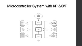
The document discusses microprocessors and their components. It describes how a microprocessor takes in numbers, performs arithmetic or logical operations according to a stored program, and produces results. The key components of a microprocessor system are the central processing unit (CPU), memory (RAM and ROM), and input/output interfaces. The CPU contains registers, an arithmetic logic unit, and a control unit. Clocks synchronize data movement and memory is addressed using address lines. Instructions are fetched and executed in machine cycles. Registers temporarily store data and addresses during operations.
Summer training embedded system and its scopeArshit Rai
CETPA INFOTECH PVT LTD is one of the IT education and training service provider brands of India that is preferably working in 3 most important domains. It includes IT Training services, software and embedded product development and consulting services.
http://www.cetpainfotech.com
This presentation is about the design and function of a microprocessor, how to program and how to interface it with other electronics machines and devices
This slides most useful for the Engineering students and Industries peoples. Hence, they are updating the knowledge of microprocessor involved in Mechatronics system.
1. Introduction to Microprocessor.pptxISMT College
Microprocessor, Microcontroller, Features/characteristics of Microprocessor, System Bus, Address Bus, Data Bus, Control Bus, Stored Program Concept, Von-Neumann Architecture, Harvard Architecture, Bus organization, Evolution of Microprocessor.
SYBSC IT SEM IV EMBEDDED SYSTEMS UNIT IV Designing Embedded System with 8051...Arti Parab Academics
Designing Embedded System with 8051 Microcontroller: Factors to be considered in selecting a controller, why 8051 Microcontroller, Designing with 8051. Programming embedded systems: structure of embedded program, infinite loop, compiling, linking and debugging.
Summer training embedded system and its scopeArshit Rai
CETPA INFOTECH PVT LTD is one of the IT education and training service provider brands of India that is preferably working in 3 most important domains. It includes IT Training services, software and embedded product development and consulting services.
http://www.cetpainfotech.com
This presentation is about the design and function of a microprocessor, how to program and how to interface it with other electronics machines and devices
This slides most useful for the Engineering students and Industries peoples. Hence, they are updating the knowledge of microprocessor involved in Mechatronics system.
1. Introduction to Microprocessor.pptxISMT College
Microprocessor, Microcontroller, Features/characteristics of Microprocessor, System Bus, Address Bus, Data Bus, Control Bus, Stored Program Concept, Von-Neumann Architecture, Harvard Architecture, Bus organization, Evolution of Microprocessor.
SYBSC IT SEM IV EMBEDDED SYSTEMS UNIT IV Designing Embedded System with 8051...Arti Parab Academics
Designing Embedded System with 8051 Microcontroller: Factors to be considered in selecting a controller, why 8051 Microcontroller, Designing with 8051. Programming embedded systems: structure of embedded program, infinite loop, compiling, linking and debugging.
Saudi Arabia stands as a titan in the global energy landscape, renowned for its abundant oil and gas resources. It's the largest exporter of petroleum and holds some of the world's most significant reserves. Let's delve into the top 10 oil and gas projects shaping Saudi Arabia's energy future in 2024.
Explore the innovative world of trenchless pipe repair with our comprehensive guide, "The Benefits and Techniques of Trenchless Pipe Repair." This document delves into the modern methods of repairing underground pipes without the need for extensive excavation, highlighting the numerous advantages and the latest techniques used in the industry.
Learn about the cost savings, reduced environmental impact, and minimal disruption associated with trenchless technology. Discover detailed explanations of popular techniques such as pipe bursting, cured-in-place pipe (CIPP) lining, and directional drilling. Understand how these methods can be applied to various types of infrastructure, from residential plumbing to large-scale municipal systems.
Ideal for homeowners, contractors, engineers, and anyone interested in modern plumbing solutions, this guide provides valuable insights into why trenchless pipe repair is becoming the preferred choice for pipe rehabilitation. Stay informed about the latest advancements and best practices in the field.
Forklift Classes Overview by Intella PartsIntella Parts
Discover the different forklift classes and their specific applications. Learn how to choose the right forklift for your needs to ensure safety, efficiency, and compliance in your operations.
For more technical information, visit our website https://intellaparts.com
Overview of the fundamental roles in Hydropower generation and the components involved in wider Electrical Engineering.
This paper presents the design and construction of hydroelectric dams from the hydrologist’s survey of the valley before construction, all aspects and involved disciplines, fluid dynamics, structural engineering, generation and mains frequency regulation to the very transmission of power through the network in the United Kingdom.
Author: Robbie Edward Sayers
Collaborators and co editors: Charlie Sims and Connor Healey.
(C) 2024 Robbie E. Sayers
Vaccine management system project report documentation..pdfKamal Acharya
The Division of Vaccine and Immunization is facing increasing difficulty monitoring vaccines and other commodities distribution once they have been distributed from the national stores. With the introduction of new vaccines, more challenges have been anticipated with this additions posing serious threat to the already over strained vaccine supply chain system in Kenya.
Hybrid optimization of pumped hydro system and solar- Engr. Abdul-Azeez.pdffxintegritypublishin
Advancements in technology unveil a myriad of electrical and electronic breakthroughs geared towards efficiently harnessing limited resources to meet human energy demands. The optimization of hybrid solar PV panels and pumped hydro energy supply systems plays a pivotal role in utilizing natural resources effectively. This initiative not only benefits humanity but also fosters environmental sustainability. The study investigated the design optimization of these hybrid systems, focusing on understanding solar radiation patterns, identifying geographical influences on solar radiation, formulating a mathematical model for system optimization, and determining the optimal configuration of PV panels and pumped hydro storage. Through a comparative analysis approach and eight weeks of data collection, the study addressed key research questions related to solar radiation patterns and optimal system design. The findings highlighted regions with heightened solar radiation levels, showcasing substantial potential for power generation and emphasizing the system's efficiency. Optimizing system design significantly boosted power generation, promoted renewable energy utilization, and enhanced energy storage capacity. The study underscored the benefits of optimizing hybrid solar PV panels and pumped hydro energy supply systems for sustainable energy usage. Optimizing the design of solar PV panels and pumped hydro energy supply systems as examined across diverse climatic conditions in a developing country, not only enhances power generation but also improves the integration of renewable energy sources and boosts energy storage capacities, particularly beneficial for less economically prosperous regions. Additionally, the study provides valuable insights for advancing energy research in economically viable areas. Recommendations included conducting site-specific assessments, utilizing advanced modeling tools, implementing regular maintenance protocols, and enhancing communication among system components.
Quality defects in TMT Bars, Possible causes and Potential Solutions.PrashantGoswami42
Maintaining high-quality standards in the production of TMT bars is crucial for ensuring structural integrity in construction. Addressing common defects through careful monitoring, standardized processes, and advanced technology can significantly improve the quality of TMT bars. Continuous training and adherence to quality control measures will also play a pivotal role in minimizing these defects.
Cosmetic shop management system project report.pdfKamal Acharya
Buying new cosmetic products is difficult. It can even be scary for those who have sensitive skin and are prone to skin trouble. The information needed to alleviate this problem is on the back of each product, but it's thought to interpret those ingredient lists unless you have a background in chemistry.
Instead of buying and hoping for the best, we can use data science to help us predict which products may be good fits for us. It includes various function programs to do the above mentioned tasks.
Data file handling has been effectively used in the program.
The automated cosmetic shop management system should deal with the automation of general workflow and administration process of the shop. The main processes of the system focus on customer's request where the system is able to search the most appropriate products and deliver it to the customers. It should help the employees to quickly identify the list of cosmetic product that have reached the minimum quantity and also keep a track of expired date for each cosmetic product. It should help the employees to find the rack number in which the product is placed.It is also Faster and more efficient way.
Final project report on grocery store management system..pdfKamal Acharya
In today’s fast-changing business environment, it’s extremely important to be able to respond to client needs in the most effective and timely manner. If your customers wish to see your business online and have instant access to your products or services.
Online Grocery Store is an e-commerce website, which retails various grocery products. This project allows viewing various products available enables registered users to purchase desired products instantly using Paytm, UPI payment processor (Instant Pay) and also can place order by using Cash on Delivery (Pay Later) option. This project provides an easy access to Administrators and Managers to view orders placed using Pay Later and Instant Pay options.
In order to develop an e-commerce website, a number of Technologies must be studied and understood. These include multi-tiered architecture, server and client-side scripting techniques, implementation technologies, programming language (such as PHP, HTML, CSS, JavaScript) and MySQL relational databases. This is a project with the objective to develop a basic website where a consumer is provided with a shopping cart website and also to know about the technologies used to develop such a website.
This document will discuss each of the underlying technologies to create and implement an e- commerce website.
Courier management system project report.pdfKamal Acharya
It is now-a-days very important for the people to send or receive articles like imported furniture, electronic items, gifts, business goods and the like. People depend vastly on different transport systems which mostly use the manual way of receiving and delivering the articles. There is no way to track the articles till they are received and there is no way to let the customer know what happened in transit, once he booked some articles. In such a situation, we need a system which completely computerizes the cargo activities including time to time tracking of the articles sent. This need is fulfilled by Courier Management System software which is online software for the cargo management people that enables them to receive the goods from a source and send them to a required destination and track their status from time to time.
Sachpazis:Terzaghi Bearing Capacity Estimation in simple terms with Calculati...Dr.Costas Sachpazis
Terzaghi's soil bearing capacity theory, developed by Karl Terzaghi, is a fundamental principle in geotechnical engineering used to determine the bearing capacity of shallow foundations. This theory provides a method to calculate the ultimate bearing capacity of soil, which is the maximum load per unit area that the soil can support without undergoing shear failure. The Calculation HTML Code included.
Industrial Training at Shahjalal Fertilizer Company Limited (SFCL)MdTanvirMahtab2
This presentation is about the working procedure of Shahjalal Fertilizer Company Limited (SFCL). A Govt. owned Company of Bangladesh Chemical Industries Corporation under Ministry of Industries.
2. What is Microprocessor?
• The Microprocessor is the programmable device that takes in numbers,
perform on them arithmetic or logical operations according to the program
stored in the memory then produces the number of results.
• Microprocessor systems are usually mounted on a single PCB comprising a
microprocessor CPU together with a no. of specialized support chips.
• These very large scale integrated (VLSI) devices provide
Input and output to the system.
Control and timing
Storage for program and data
Typical applications : control of complex industrial processes
Typical examples: based on families of chips such as Z80 CPU plus Z80 PIO,
Z80CTC, Z80 SIO.
3. Single Chip Microcomputers
• A single chip microcomputer is a complete computer system (comprising
CPU, RAM ,ROM etc) in a single VLSI package.
• It requires very little external circuitry in order to provide all of the functions
associated with a complete computer system (with limited and output
capability).
• They may be programmed using in-built programmable memories or via
external memory chips.
• Typical applications : computer printers, instrument controllers , display
• Typical examples: Z84C
4. Microcontrollers
• A microcontroller is a single chip microcomputer that is designed
specifically for control rather than general purpose applications.
• They are often used to satisfy a particular control requirement such as
controlling a motor drive.
• Single chip microcomputers on the other hand perform a variety of
different functions and may control several processes at the same time.
• Typical applications : motor, printers, drivers , several sub system
components
• Typical examples: Z86E ,8051 , 68705 ,89C51
5. PIC Microcontroller
• A PIC microcontroller is a general purpose microcontroller device that is normally
used in a standalone application.
• Performs simple logic, timing and input/ output control.
• PIC devices provide a flexible low cost solution that very effectively bridges the gap
between single- chip computers and the use of discrete logic and timer chips.
• A no. of PIC and microcontroller devices have been produced that incorporate a
high level language interpreter.
• The resident interpreter allows developers to develop their programs such as
BASIC rather than having to resort to more complex assembly language.
• This feature makes PIC microcontrollers very easy to use.
• PIC microcontrollers are used in ‘self-contained’ applications involving logic, timing
simple A/D & D/A conversion.
• Typical examples: PIC 12C508 ,PIC 16C620
6. Programmed Logic Devices(PLD)
• PLD is a programmable chip that can carry out complex logical operations.
• It is not a microprocessor device.
• PLDs are capable of replacing a large no. of conventional logic gates .
• This minimizes chip count and reduces printed circuit board sizes.
• Programming is relatively straight forward and requires the derivation of
complex logic functions using Boolean algebra or truth tables.
• Typical examples: 16 L8, 24V10
7. Programmable logic controller
• PLCs are microprocessor based systems.
• Used for controlling a wide variety of automatic processes.
• Designed specifically for operations in process control environment.
• The control program for a PLC is generally stored in one or more
semiconductor memory devices.
• The program can be entered (or modified) by means of a simple hand held
programmer, laptop controller , or downloaded over a local area network.
• PLC manufacturers include Allen Bradley , Siemens and Mitsubishi
9. Microprocessor System
• The basic components of any microprocessor system (see Fig.
11.1) are:
• (a) a central processing unit (CPU)
• (b) a memory, comprising both ‘read/write’ and ‘read only’
devices (commonly called RAM and ROM respectively)
• (c) a means of providing input and output (I/O).
• For example, a keypad for input and a display for output.
10. Microprocessor System
• The basic components of the system (CPU, RAM, ROM and I/O) are linked
together using a multiple-wire connecting system know as a bus (see Fig.
11.1). Three different buses are present, these are:
(a) the address bus used to specify memory locations;
(b) the data bus on which data is transferred between devices; and
(c) the control bus which provides timing and control signals throughout the
system.
11. Microprocessor System
• The number of individual lines present within the address bus and data
bus depends upon the particular microprocessor employed.
• Signals on all lines, no matter whether they are used for address, data, or
control, can exist in only two basic states: logic 0 (low) or logic 1 (high)
• Data and addresses are represented by binary numbers (a sequence of 1s
and 0s) that appear respectively on the data and address bus
12. Data and Address bus
• The largest binary number that can appear on an 8-bit data bus corresponds to
the condition when all eight lines are at logic 1.
• Therefore the largest value of data that can be present on the bus at any instant
of time is equivalent to the binary number 11111111 (or 255). Similarly, most the
highest address that can appear on a 16-bit address bus is1111111111111111 (or
65,535).
• The full range of data values and addresses for a simple microprocessor of this
type is thus:
• Data from 00000000
to 11111111
• Addresses from 0000000000000000
• to 1111111111111111
14. Data Types:
• A byte of data can be stored at each address within
the total memory space of a microprocessor system.
• Hence one byte can be stored at each of the 65,536
memory locations within a microprocessor system
• having a 16-bit address bus.
• Individual bits within a byte are numbered from 0
(least significant bit) to 7 (most significant bit). In the
case of 16-bit words, the bits are numbered from 0
(least significant bit) to 15 (most significant bit).
• Negative (or signed) numbers can be represented
using two’s complement notation where the leading
(most significant) bit indicates the sign of the number
(1 = negative, 0 = positive).
16. Microprocessor
• The microprocessor central processing unit (CPU) forms the heart of any
microprocessor or microcomputer system computer and, consequently, its
operation is crucial to the entire system.
• The primary function of the microprocessor is that of fetching, decoding, and executing
instructions resident in memory.
• As such, it must be able to transfer data from external memory into its own internal
registers and vice versa.
• The main parts of a microprocessor CPU are:
• (a) registers for temporary storage of addresses and data;
• (b) an arithmetic logic unit (ALU) that performs arithmetic and logic operations;
• (c) a unit that receives and decodes instructions;
• (d) a means of controlling and timing operations within the system
17. Accumulator (A - register)
• Accumulator functions as a source and destination register for many of the
basic microprocessor operations.
• Source register: Contains the data that will be used in a particular
operation.
• Destination register: used to hold the result of a particular operation.
• Accumulator features in a very large no. of microprocessor operations , so
more reference is made to this register than others.
18. Instruction register
• Provides a temporary storage location in which the current microprocessor
instruction is held while it is decoded.
• Program instructions are passed into the microprocessor one at a time through
the data bus.
• Machine cycle:
• First cycle instruction is fetched and decoded
• Subsequent cycles : instruction is executed Each machine cycle takes a finite
time (less than a microsecond) depending upon the frequency of the
microprocessor clock.
19. Data bus (D0 to D7)
• The external data bus provides a highway for data that links all of the
system components (ROM,RAM,I/O devices) together.
• 8 bit system: 8 data lines , labelled D0 (least significant bit) to D7 (most
significant bit).
• Data is moved around in group of 8 bits, or bytes.
• 16 bit system : labelled D0 (least significant bit) to D15 (most significant bit)
and so on.
20. Data Buffer
• It is a temporary register.
• Bytes of data pass on their way into and out of the microprocessor.
• Bidirectional
• The buffer is thus referred to as bidirectional with data passing out of the microprocessor on
a write operation and into the processor during read operation.
• Control unit
• The direction of data transfer is controlled by the control unit as it responds to each
individual program instruction.
• Internal data bus
• It is a high speed data highway that links all of the microprocessors internal elements
together.
• Data is constantly flowing forward and backward along the internal data bus lines.
21. General Purpose Register
• Many microprocessor operations (example: adding two 8 bit numbers) require the use of more
than one registers.
• There is a requirement for temporarily storing the partial result of an operation when other
operation take place.
• These needs can be met by providing a no. of general purpose registers.
• Stack pointer
• Stack pointer is simply a register that contains the last used stack location.
• Most microprocessors make use of a region of external Random access Memory (RAM) known
as a stack to suspend a particular task in order to briefly attend something else.
• When the main program is interrupted, microprocessor temporarily places the stack contents of
its internal registers together with the address of the next instruction in the main program
• When the interrupt is attended , microprocessor recovers the data that has been stored
temporarily with the address of next instruction within the main program.
• It is thus able to return to the main program exactly where it left off and all the data preserved in
its registers.
22. General Purpose Register
• Program counter
• Programs consists of a sequence of instructions that are executed by
microprocessor.
• These instructions are stored in external RAM or ROM.
• Instructions must be fetched and executed by the microprocessor in a strict
sequence.
• By storing the address of the next instruction to be executed, the program counter
allows the microprocessor to keep track of where it is within the program.
• The program counter is automatically incremented when each instruction is
executed.
23. General Purpose Register
• Address bus buffer
• Address bus buffer is a temporary register through which addresses (16 bits)
pass on their way out of the microprocessor.
• In a simple microprocessor the address buffer is unidirectional with addresses
placed on the address bus during both read and write operations.
• Address bus lines are labelled A0(least significant address bus line) to
A15(most significant address bus line).
• A 16 bit address line can be used to communicate with 65,536 individual
locations.
• At each location a single byte of data is stored.
24. Control Bus
• It is a collection of signal lines that are used to control the transfer of data
around the system and also to interact with the external devices.
• The control signals used by the microprocessors tend to differ with different
types.
• Commonly found control signals are given below
26. Address bus A0 to A15
• Provides a highway for addresses that links all of the system components
(ROM,RAM,I/O devices) together.
• 16 bit system has 16 address lines , labelled A0 (least significant bit) to A15
(most significant bit).
• 32 bit system has 32 address lines ,labelled A0 (least significant bit) to A31
(most significant bit) and so on.
27. • Instruction decoder
• It is an arrangement of logic gates that acts on the bits stored in the instruction
register and determines which instruction is currently being referred.
• It provides output signals for the microprocessor's control unit.
• Control unit
• It is responsible for organizing the orderly flow of data within the microprocessor as
well as generating and responding to signals on the control bus.
• It is also responsible for timing all data transfers.
• This process is synchronized using an internal or external clock signal.
28. Arithmetic Logic Unit
• Performs arithmetic and logic operations. It has 2 inputs (here ,8 bits wide).
• One input is derived from the accumulator and the other from the internal data bus via a
temporary register.
• Operations provided by ALU : addition, subtraction, logical AND ,logical OR, logical
exclusive-OR, shift right, shift left etc.
• The result of most ALU operations are stored in accumulator.
• Flag register (status register)
• The result of an ALU operation is sometimes important in determining what subsequent
operation takes place.
• A flag register contains a no. of individual bits that are set or reset according to the result
of an ALU operation. These bits are referred to as flags.
• The following flags are available in microprocessor
30. Clocks
• The clock used in a microprocessor system is an accurate and stable square wave
generator.
• In most crystals, the frequency of the square wave generator is determined by the
quartz crystal.
• A simple 4 MHz square wave clock oscillator (together with clock waveform it
produces) is shown below.
• One complete clock cycle is referred to as T-state.
• Microprocessors sometimes have an internal clock circuit where the quartz
crystal(or resonant device) is connected to pins directly on the microprocessor
chip.
32. Microprocessor Operation
• Majority of operations performed by a microprocessor involves movement of data.
• The program code (a set of instructions stored in RAM or ROM)must itself be fetched
from memory prior to execution.
• Microprocessor performs a continuous sequence of instruction fetch and execution
cycles.
• The process of fetching an instruction code (or operand or data value) from memory
involves a read operation .
• The process of moving data from microprocessor to memory involves a write
operation.
33. Microprocessor Operations
• Machine cycle:
• Each cycle of CPU operation is known as machine cycle.
• Program instructions may require several machine cycles (typically between
2 and 5).
• The first machine cycle in any cycle consists of an instruction fetch
(instruction code is read from memory) and is known as M1 cycle.
• Subsequent cycles M2,M3 and so on, depend on the type of instruction that
is being executed.
• The fetch –execute sequence is shown in Fig 6.
• Microprocessors determine the source of data (when it is being read) and
destination of data (when it is being written)by placing a unique address on
the address bus.
35. Address decoding logic.
• The data bus is connected to a no. of VLSI devices .
• An essential requirement of such chips (RAM or ROM) is that their data outputs
should be capable of being isolated from the bus whenever necessary.
• These chips are fitted with select or enable inputs that are driven by address
decoding logic.
• This logic ensures that RAM,ROM,I/O devices never simultaneously try to
attempt data on the bus.
• The inputs of the address decoding logic are derived from one or more of the
address bus lines.
• The address decoder effectively divides the available memory into blocks
corresponding to a particular function (RAM, ROM, I/O etc).
• When the processor is writing to RAM, the address decoder logic will ensure that
RAM is selected ,while ROM and I/O remain isolated from the bus.
37. Registers
• Within the CPU ,data is stored in several registers.
• Registers can be thought of as a simple pigeon- hole arrangement that can store
as many bits as there are holes available.
• These devices can store groups of 16 or 32 bits.
• Some registers may be configured as either one register of 16 bits or two registers
of 32 bits.
• Some microprocessor programs are accessible to the programmers while others
are used by the microprocessor itself.
• Registers may be classified as
• o General purpose registers
• o Dedicated : a particular function is associated with the register(holding the result
of an operation or signalling the result of a comparison).
• A typical microprocessor and its register model is shown below
39. Arithmetic Logic Unit(ALU)
• ALU can perform arithmetic operations (addition and subtraction) and logical
operation (logialAND,logical OR).
• ALU operates on two inputs (16 or 32 bits depending upon the CPU type) and
provides one output (16 or 32 bits).
• ALU status is preserved in the flag register( an overflow, zero or negative result
can be detected).
• The control unit is responsible for the movement of data within the CPU and the
management of control signals both internal and external.
• The control unit asserts the requisite signals to read or write data as
appropriate to the current instruction.
40. Input and Output
• Parallel data transfer
• The transfer of data within a microprocessor involves moving groups of 8, 16,32 bits
using the bus architecture.
• It is simple to transfer data into and out of the system in parallel form.
• This process is simplified using a Programmable Parallel I/O device (a Z80PIO , 8255
or equivalent VLSI chip).
• This device provides register for the temporary storage of data .
• This device not only buffer the data and also provides a degree of electrical isolation
from the system data bus.
• Parallel data transfer is generally suited to high speed operation over relatively short
distances.
• Example : linking of a microcomputer to an adjacent dot matrix printer.
42. Input and Output
• Parallel to serial data conversion
• In some applications like data communication by means of telephone lines , parallel data transfer
is inappropriate.
• In such cases , data must be sent serially (one bit after another).
• To transmit data in serial form, the parallel data from the microprocessor must be reorganized
into a stream of bits.
• This task is simplified by using an LSI interface device.
• LSI interface device contains a shift register that is loaded with parallel data from the serial bus.
• This data is read out as a serial bit stream by successive shifting.
• Serial to parallel data conversion
• The reverse process (serial to parallel) also uses a shift register.
• Data is placed simultaneously on the parallel output lines.
44. Interrupts:
• A program that executes a loop indefinitely has a limitation.
• In most microprocessor systems there is a need to interrupt the normal sequence of program flow in order to alert the
microprocessor the need to do something.
• This is done with a signal known as interrupt.
• There are two types of interrupt maskable and non maskable.
• Non -Maskable interrupt
• When this interrupt is asserted , the processor must suspend execution of current instruction and respond immediately
to the interrupt.
• Maskable interrupt
• The processor`s response will depend upon whether interrupts are currently enabled or disabled.
• When enabled, the CPU will suspend its current task and carry out the interrupt service routine.
• The response to interrupts can be enabled or disabled by means of appropriate program instructions.
• Interrupt signals may be generated from a no. of sources.
• Each will require its own customized response, a mechanism must be provided for identifying the source of interrupt and
calling the appropriate interrupt service routine.
• For this task , the microprocessor may use a dedicated programmable interrupt controller chip.
45. Microcontroller Systems
• The arrangement of a typical microcontroller system is shown below.
• The sensed quantities (temperature, position etc.) are converted corresponding
electrical signals by means of a no. of sensors .
• The output from the sensors (either analog or digital) are passed as input signals to the
microcontroller.
• The microcontroller also accepts input from the user.
• These user set options typically include target values for variables (desired room
temperature), limit values (maximum shaft speed) or time constraints (‘on’ time, ‘off’
time, delay time etc.).
• The operation of microcontroller is controlled by a sequence of software instructions
known as a control program.
46. Microcontroller Systems
• The control program operates continuously , examining inputs from the sensors
,user settings and time data before making changes to the output signals sent
to one or more controlled devices.
• The controlled quantities are produced by the control devices in response to
output signals from the microcontroller.
• The controlled device generally converts energy in one form into energy in
another form.
• Example : the controlled device might be an electric heater which converts
electrical energy from the AC mains supply into heat energy thus producing a
given temperature (controlled quantity).
47. Microcontroller Systems
• In most real world systems , there is a requirement for the system to be automatic or self
– regulating.
• Once set , such systems will continue to operate without continuous operator
intervention.
• The output of a self - regulating system is fed back to its input in order to produce a
closed loop system.
• Example of closed loop system: a heating control system that is designed to maintain a
constant room Temperature and humidity within a building regardless of changes in the
outside conditions.
48. • A microcontroller must produce a specific state on each of the lines connected to
its output ports in response to a particular combination of states present on each
of the lines connected to its input ports.
• Microcontrollers also have a CPU capable of performing simple arithmetic,
logical and timing operations.
• The input port signals are derived from a no. of sources including
• Switches : (including momentary action push buttons)
• Sensors : (producing logic-level compatible outputs)
50. • Input devices
• Input devices supplies input to the computer system from the outside world.
• Input devices available on a PC are mouse (pointing device), scanner and modem.
• Microcontrollers use simple input devices.
• They may be individual switches or contacts that make and break .
• Many types of sensors that provide logic level outputs are also used (float switches
,proximity devices ,light sensors) .
• To connect directly to the input port of a microcontroller , the input dvice must provide a
logic compatible signal.
51. • This is because the microcontroller signals can only accept digital input signals with the
same voltage levels as the logic power source.
• The 0 V ground level (VSS in CMOS microcontroller) and the positive power supply
(VDD in CMOS microcontroller) is invariably 5V ± 5 %.
• A level of approximately 0 V indicates a logic 0 signal and a voltage approximately equal
to the positive power supply indicates a logic 1 signal.
• Other input device must sense analogue quantities (such as velocity) but uses a digital
code to represent their value as an input to the microcontroller system.
• Some microcontrollers provide an internal analogue to digital converter (ADC) in order to
simplify the connection of analogue sensors as input devices.
• If there is no internal ADC, it will be necessary to use an external ADC which usually
takes the form of a single integrated circuit.
52.
53. • Output devices
• These are used to communicate information or actions from a control system to
the outside world.
• Output devices in PC are CRT (cathode ray tube) display, printers and modems.
• Microcontrollers use simple output devices.
• They may be LEDs , piezoelectric sounders, relays and motors.
• To connect directly to the output port of a microcontroller the output device must
be able to accept a logic compatible signal.
• Analogue quantities (rather than digital on/off) are required at the output of the
digital- to- analog converter.
• All functions associated with the DAC can be provided by a single integrated
circuit.
• The output resolution of DAC will depend upon the no. of bits used.
• 8, 10,12 bit devices are common in control applications.
54.
55. Interface Circuits
• When input and output devices are logically not compatible i.e when they are
outside the range of signals that can be connected directly to the
microcontroller.
• Some additional interface circuitry may be required to shift the voltage levels
or to provide additional current drive.
• Additional circuitry may also be required , when a load (such as relay and
motors) requires more current than is available from a standard logic device
or output port.
• Example : a common range of interface circuits (solid state relays) is
available that will allow a microcontroller to be easily interfaced to an AC
mains – connected load.
• It then becomes possible for a small microcontroller (operating from only a 5V
dc supply) to control a central heating system operating from 240V AC mains.