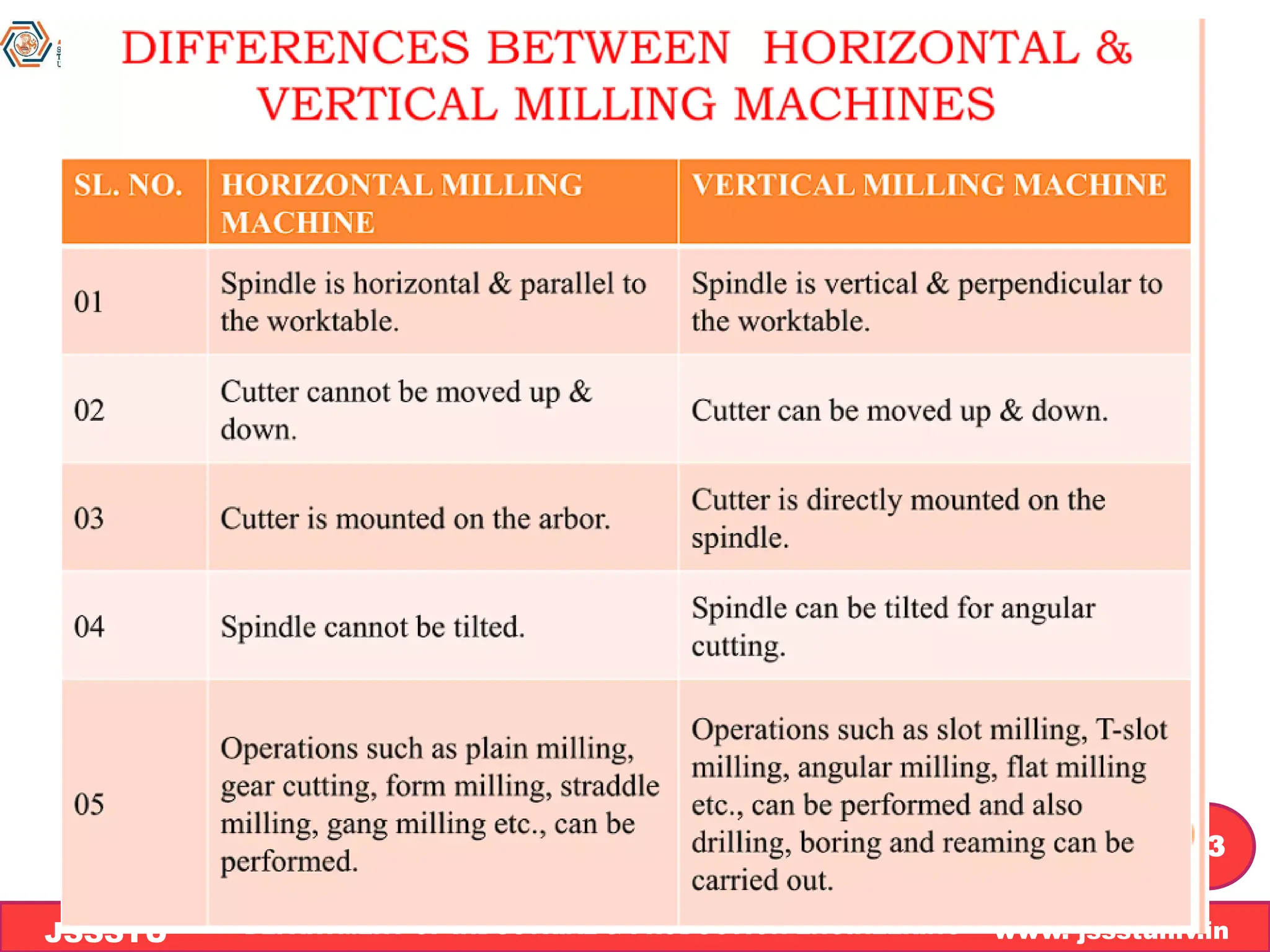
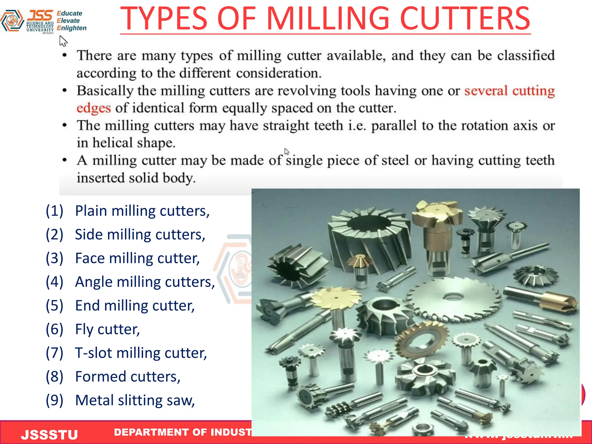
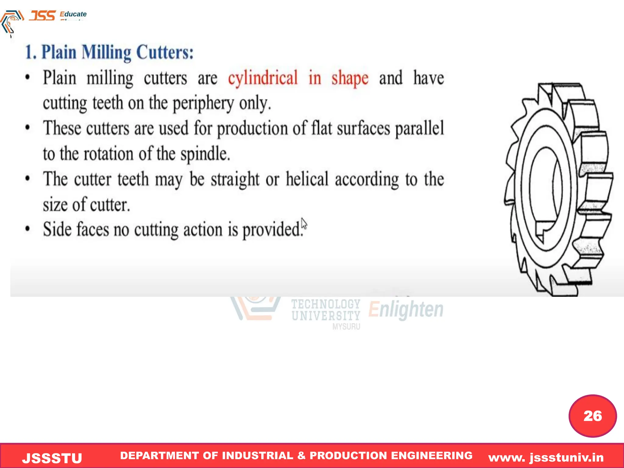
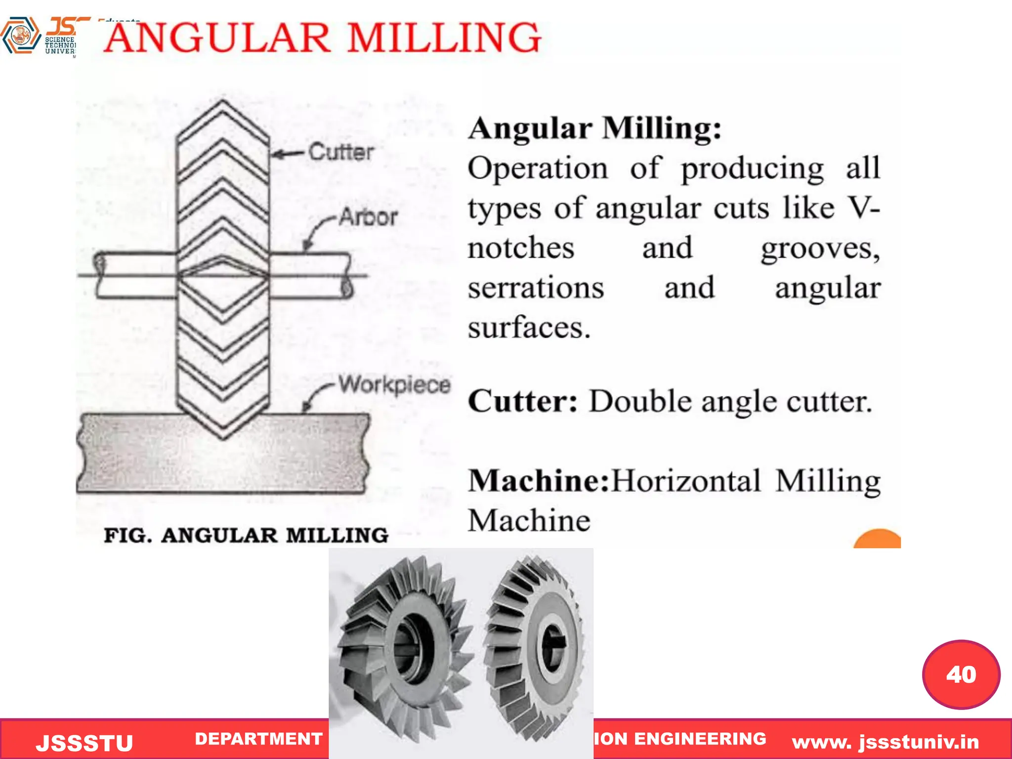
DEPARTMENT OF INDUSTRIAL & PRODUCTION ENGINEERING www. jssstuniv.in
JSSSTU
R
L
J
I
T
Module-4
Shaping & Gear shaping Machines
Milling Machines
Course Instructor
Vijay Praveen P M
Assistant Professor
Department of I&P Engg.
DEPARTMENT OF INDUSTRIAL & PRODUCTION ENGINEERING www. jssstuniv.in
JSSSTU
R
L
J
I
T
2
syllabus
Shaping and Gear Shaping Machines: Construction
features, and operations of Shaping and Gear
Shaping Machines, horizontal broaching machines
for cutting gear teeth .
Milling Machines: Classification, constructional
features, milling cutters nomenclatures, Milling
operations, up milling and down milling concepts
and its applications .
DEPARTMENT OF INDUSTRIAL & PRODUCTION ENGINEERING www. jssstuniv.in
JSSSTU
R
L
J
I
T
3
Milling Machines
DEPARTMENT OF INDUSTRIAL & PRODUCTION ENGINEERING www. jssstuniv.in
JSSSTU
R
L
J
I
T
4
Introduction
➢ A milling machine is a machine tool that removes metal as the work is fed
against a rotating multipoint cutter.
➢ The milling cutter rotates at high speed and it removes metal at a very
fast rate with the help of multiple cutting edges
➢ In the milling process, the workpiece is normally fed into a rotating cutting
tool known as milling cutter.
➢ Equally spaced peripheral teeth on the cutter come in contact with the
workpiece intermittently and machine the workpiece. This is called
intermittent cutting.
➢ Milling machines are used to produce parts having flat as well as curved
shapes.
➢ Intricate shapes, which cannot be produced on the other machine tools,
can be made on the milling machines
DEPARTMENT OF INDUSTRIAL & PRODUCTION ENGINEERING www. jssstuniv.in
JSSSTU
R
L
J
I
T
5
DEPARTMENT OF INDUSTRIAL & PRODUCTION ENGINEERING www. jssstuniv.in
JSSSTU
R
L
J
I
T
6
Principle of milling
• In milling machine, the metal is cut by means of a
rotating cutter having multiple
• cutting edges. For cutting operation, the workpiece
is fed against the rotary cutter. As the workpiece
moves against the cutting edges of milling cutter,
metal is removed in form chips
DEPARTMENT OF INDUSTRIAL & PRODUCTION ENGINEERING www. jssstuniv.in
JSSSTU
R
L
J
I
T
7
DEPARTMENT OF INDUSTRIAL & PRODUCTION ENGINEERING www. jssstuniv.in
JSSSTU
R
L
J
I
T
8
MILLING METHODS
• There are two distinct methods of milling
classified as follows:
• 1. Up-milling or conventional milling, and
• 2. Down milling or climb milling.
DEPARTMENT OF INDUSTRIAL & PRODUCTION ENGINEERING www. jssstuniv.in
JSSSTU
R
L
J
I
T
9
Up-milling or conventional milling
➢ In ‘‘upmilling process’’, the workpiece is fed opposite to the
cutter’s tangential velocity.
➢ Each tooth of the cutter starts the cut with zero depth of cut,
which gradually increases and reaches the maximum value as
the tooth leaves the cut.
➢ The chip thickness at the start is zero increases to maximum at
the end of the cut.
DEPARTMENT OF INDUSTRIAL & PRODUCTION ENGINEERING www. jssstuniv.in
JSSSTU
R
L
J
I
T
10
• The major disadvantages of up-milling
process are the tendency of cutting force
to lift the work from the fixtures and poor
surface finish obtained. But being a safer
process, it is commonly used method of
milling.
DEPARTMENT OF INDUSTRIAL & PRODUCTION ENGINEERING www. jssstuniv.in
JSSSTU
R
L
J
I
T
11
Down-Milling or Climb Milling
➢ In this method, the metal is removed by a cutter
rotating in the same direction of feed of the
workpiece.
➢ The effect of this is that the teeth cut downward
instead of upwards.
➢ Chip thickness is maximum at the start of the cut and
minimum in the end.
DEPARTMENT OF INDUSTRIAL & PRODUCTION ENGINEERING www. jssstuniv.in
JSSSTU
R
L
J
I
T
12
➢In this method, it is claimed that there is less
friction involved and consequently less heat is
generated on the contact surface of the cutter and
workpiece
➢Climb milling can be used advantageously on many
kinds of work to increase the number of pieces
per sharpening and to produce a better finish.
➢ With climb milling, saws cut long thin slots more
satisfactorily than with standard milling.
DEPARTMENT OF INDUSTRIAL & PRODUCTION ENGINEERING www. jssstuniv.in
JSSSTU
R
L
J
I
T
13
DEPARTMENT OF INDUSTRIAL & PRODUCTION ENGINEERING www. jssstuniv.in
JSSSTU
R
L
J
I
T
14
Classification of Milling Machines
1. Column and knee type :
(i) Horizontal milling machine.
(ii) Vertical milling machine.
(iii) Universal milling machine.
2. Manufacturing or fixed bed type :
(i) Simplex milling machine.
(ii) Duplex milling machine.
(iii) Triplex milling machine.
3. Planer type :
4. Special type :
(i) Rotary table milling machine.
(ii) Drum milling machine.
(iii) Planetary milling machine.
(iv) Pantograph, profiling and tracer controlled milling
machine.
DEPARTMENT OF INDUSTRIAL & PRODUCTION ENGINEERING www. jssstuniv.in
JSSSTU
R
L
J
I
T
15
DEPARTMENT OF INDUSTRIAL & PRODUCTION ENGINEERING www. jssstuniv.in
JSSSTU
R
L
J
I
T
16
Horizontal Milling Machine
• Base
• Column
• Knee
• Saddle
• Table
• Arbor
• Spindle
DEPARTMENT OF INDUSTRIAL & PRODUCTION ENGINEERING www. jssstuniv.in
JSSSTU
R
L
J
I
T
17
DEPARTMENT OF INDUSTRIAL & PRODUCTION ENGINEERING www. jssstuniv.in
JSSSTU
R
L
J
I
T
18
.1. Base :
It is a heavy casting on which column and other parts are
mounted.
▪ It may be bolted to the floor strongly.
▪ 2. Column :
▪ There are guideways on the front face of the column, on which
the knee slides.
▪ It houses power transmission units such as gears, belt drives
and pulleys to give rotary motion to the arbor. The drive
mechanisms are also used to give automatic feed to the
handle and table.
▪ 3. Knee :
▪ It supports the saddle, table, workpiece and other clamping
devices.
▪ It moves on guideways of the column.
DEPARTMENT OF INDUSTRIAL & PRODUCTION ENGINEERING www. jssstuniv.in
JSSSTU
R
L
J
I
T
19
▪ 4. Saddle :
▪ It is mounted on the knee and can be moved by a handwheel or by
power.
▪ The direction of travel of the saddle is restricted to be towards or
away from the column face.
▪ 5. Table :
▪ It is mounted on the saddle and can be moved by a handwheel or
by power.
▪ Its top surface is machined accurately to hold the workpiece and
other holding devices.
▪ It moves perpendicular to the direction of saddle movement.
▪ 6. Arbor :
▪ Its one end is attached to the column and the other end is
supported by an overarm.
▪ It holds and drives different types of milling cutters.
▪ 7. Spindle :
▪ It gets power from gears, belt drives, to drive the motor.
▪ It has provision to add or remove milling cutters onto the arbor.
DEPARTMENT OF INDUSTRIAL & PRODUCTION ENGINEERING www. jssstuniv.in
JSSSTU
R
L
J
I
T
20
Vertical Milling Machine
In vertical milling machine, the position of the spindle head is
vertical and the axis of the spindle is perpendicular to the work
table as shown in fig .
DEPARTMENT OF INDUSTRIAL & PRODUCTION ENGINEERING www. jssstuniv.in
JSSSTU
R
L
J
I
T
21
In this machine both the ‘base’ and ‘column’ are integral castings.
➢ The spindle head can be moved up and down over the guideways.
The vertical milling machine may have fixed head, swiveling head
or slidable swiveling head spindle.
➢ The ‘saddle’ is mounted on a ‘knee’ which can be mould up and
down over the guideways provided on the column face. The
saddle can be moved horizontally either by hand or by power
over the knee guideways.
➢ The worktable mounted on the saddle can be moved
longitudinally over the guideways provided on the top of the
saddle.
➢ In this machine, the workpiece can be moved both in the vertical
plane and on the horizontal plane.
➢ The machine is used to machine grooves, slots and flat surfaces
using end mill and face mill cutters.
DEPARTMENT OF INDUSTRIAL & PRODUCTION ENGINEERING www. jssstuniv.in
JSSSTU
R
L
J
I
T
22
DEPARTMENT OF INDUSTRIAL & PRODUCTION ENGINEERING www. jssstuniv.in
JSSSTU
R
L
J
I
T
23
DEPARTMENT OF INDUSTRIAL & PRODUCTION ENGINEERING www. jssstuniv.in
JSSSTU
R
L
J
I
T
24
Specifications of a Milling Machine
The following are the specifications of a
column and knee type milling machine :
1. Width and length of the table.
2. Maximum distance the knee can travel.
3. Maximum longitudinal movement and cross
feed of the table.
4. Number of spindle speeds.
5. Power of the main drive motor.
DEPARTMENT OF INDUSTRIAL & PRODUCTION ENGINEERING www. jssstuniv.in
JSSSTU
R
L
J
I
T
25
TYPES OF MILLING CUTTERS
(1) Plain milling cutters,
(2) Side milling cutters,
(3) Face milling cutter,
(4) Angle milling cutters,
(5) End milling cutter,
(6) Fly cutter,
(7) T-slot milling cutter,
(8) Formed cutters,
(9) Metal slitting saw,
DEPARTMENT OF INDUSTRIAL & PRODUCTION ENGINEERING www. jssstuniv.in
JSSSTU
R
L
J
I
T
26
DEPARTMENT OF INDUSTRIAL & PRODUCTION ENGINEERING www. jssstuniv.in
JSSSTU
R
L
J
I
T
27
DEPARTMENT OF INDUSTRIAL & PRODUCTION ENGINEERING www. jssstuniv.in
JSSSTU
R
L
J
I
T
28
DEPARTMENT OF INDUSTRIAL & PRODUCTION ENGINEERING www. jssstuniv.in
JSSSTU
R
L
J
I
T
29
DEPARTMENT OF INDUSTRIAL & PRODUCTION ENGINEERING www. jssstuniv.in
JSSSTU
R
L
J
I
T
30
DEPARTMENT OF INDUSTRIAL & PRODUCTION ENGINEERING www. jssstuniv.in
JSSSTU
R
L
J
I
T
31
DEPARTMENT OF INDUSTRIAL & PRODUCTION ENGINEERING www. jssstuniv.in
JSSSTU
R
L
J
I
T
32
DEPARTMENT OF INDUSTRIAL & PRODUCTION ENGINEERING www. jssstuniv.in
JSSSTU
R
L
J
I
T
33
DEPARTMENT OF INDUSTRIAL & PRODUCTION ENGINEERING www. jssstuniv.in
JSSSTU
R
L
J
I
T
34
DEPARTMENT OF INDUSTRIAL & PRODUCTION ENGINEERING www. jssstuniv.in
JSSSTU
R
L
J
I
T
35
DEPARTMENT OF INDUSTRIAL & PRODUCTION ENGINEERING www. jssstuniv.in
JSSSTU
R
L
J
I
T
36
DEPARTMENT OF INDUSTRIAL & PRODUCTION ENGINEERING www. jssstuniv.in
JSSSTU
R
L
J
I
T
37
Milling Operations
1. Plain or slab milling
2. Face milling
3. Angular milling
4. Form milling
5. Straddle milling
6. Gang milling
7. End milling
8. slot milling
9. Saw milling
10. Involute gear cutting.
DEPARTMENT OF INDUSTRIAL & PRODUCTION ENGINEERING www. jssstuniv.in
JSSSTU
R
L
J
I
T
38
. 1.Plain or slab milling. Plain milling is used to
machine flat and horizontal surfaces
Here plain milling cutter is used, which is held in
the arbor and rotated. The table is moved
upwards to give the required depth of cut.
It is carried on Horizontal Milling Machine
DEPARTMENT OF INDUSTRIAL & PRODUCTION ENGINEERING www. jssstuniv.in
JSSSTU
R
L
J
I
T
39
2. Face milling. This milling process is used for
machining a flat surface which is at right angles to
the axis of the rotating cutter.
The cutter used in this operation is the face milling
cutter
It is carried on vertical milling Machine
DEPARTMENT OF INDUSTRIAL & PRODUCTION ENGINEERING www. jssstuniv.in
JSSSTU
R
L
J
I
T
40
DEPARTMENT OF INDUSTRIAL & PRODUCTION ENGINEERING www. jssstuniv.in
JSSSTU
R
L
J
I
T
41
4.Form milling: This milling process is used for machining
those surfaces which are of irregular shapes.
The irregular shape may be convex, concave,or of any other
shape..
The form milling cutter used has the shape of its cutting teeth
conforming to the profile of the surfaces to be produced.
It is carried on Horizontal Milling M/C
DEPARTMENT OF INDUSTRIAL & PRODUCTION ENGINEERING www. jssstuniv.in
JSSSTU
R
L
J
I
T
42
5. Straddle milling. Straddling milling is an operation in
which a pair of side milling cutters is used for machining
two parallel vertical surfaces of a workpiece
simultaneously.
The distance between the cutters is adjusted by the
spacers.
This process is used to mill square and hexagonal
surfaces.
Is carried on Horizontal Milling Machine
DEPARTMENT OF INDUSTRIAL & PRODUCTION ENGINEERING www. jssstuniv.in
JSSSTU
R
L
J
I
T
43
➢ 6. Gang milling. is the name given to a milling operation which
involves the use of a combination of more than two cutters,
mounted on a common arbor, for milling a number of flat
horizontal and vertical surfaces of a workpiece
simultaneously.
➢ This method saves much of machining time and is widely
used in repetitive work. The cutting speed of a gang of cutters
is calculated from the cutter of the largest diameter.
➢ Is carried on Horizontal Milling Machine
DEPARTMENT OF INDUSTRIAL & PRODUCTION ENGINEERING www. jssstuniv.in
JSSSTU
R
L
J
I
T
44
7. End milling. It is an operation of producing narrow
slots, grooves and keyways using an end mill cutter.
The mill tool may be attached to the vertical spindle
for milling the slot. Depth of cut is given by raising
the machine table.
Is carried on Vertical Milling Machine
DEPARTMENT OF INDUSTRIAL & PRODUCTION ENGINEERING www. jssstuniv.in
JSSSTU
R
L
J
I
T
45
DEPARTMENT OF INDUSTRIAL & PRODUCTION ENGINEERING www. jssstuniv.in
JSSSTU
R
L
J
I
T
46
9. Saw milling. It is an operation of producing narrow
grooves and slots on the workpiece.
A slitting saw cutter is used for saw milling
• The saw-milling also performed for complete
parting-off operation.
Is carried on Horizontal Milling Machine
DEPARTMENT OF INDUSTRIAL & PRODUCTION ENGINEERING www. jssstuniv.in
JSSSTU
R
L
J
I
T
47
10. Involute gear cutting. Gear milling operation,
often referred as gear cutting, involves cutting of
different types of gears on a milling machine.
For this, either an end mill cutter or a form
relieved cutter is used
It is carried on vertical or horizontal milling M/C
DEPARTMENT OF INDUSTRIAL & PRODUCTION ENGINEERING www. jssstuniv.in
JSSSTU
R
L
J
I
T
48
DEPARTMENT OF INDUSTRIAL & PRODUCTION ENGINEERING www. jssstuniv.in
JSSSTU
R
L
J
I
T
49
Milling Cutter Nomenclature
DEPARTMENT OF INDUSTRIAL & PRODUCTION ENGINEERING www. jssstuniv.in
JSSSTU
R
L
J
I
T
50
• Body :The main frame of the cutter on which the teeth rests
to form integral part is called as body of cutter.
• Outside diameter ; It is the diameter of the circle passing
through the peripheral cutting EDGE
• Face: It is a surface of cutting tooth against which the chip is
forced in the metal cutting operation
• Land : It is the back part of the tooth adjacent to the cutting
edge
• Flute: The flute is the chip space between the back of the
tooth and face of the following tooth
• Cutting edge: It is the intersection of the face of the tool with
the leading edge of the land
DEPARTMENT OF INDUSTRIAL & PRODUCTION ENGINEERING www. jssstuniv.in
JSSSTU
R
L
J
I
T
51
Important Questions
1.Write a note on up miling and down milling with
neat sketch
2. What is the difference between Up milling & Down
milling
3. Write a note on classification of milling M/C and
explain with a neat sketch construction and features
of Horizontal Milling Machine
4. explain with a neat sketch construction and
features of Vertical Milling Machine
5. discuss the milling operations

Module 4 Milling , Shaping & gear shaping.pdf

  • 1.
    DEPARTMENT OF INDUSTRIAL& PRODUCTION ENGINEERING www. jssstuniv.in JSSSTU R L J I T Module-4 Shaping & Gear shaping Machines Milling Machines Course Instructor Vijay Praveen P M Assistant Professor Department of I&P Engg.
  • 2.
    DEPARTMENT OF INDUSTRIAL& PRODUCTION ENGINEERING www. jssstuniv.in JSSSTU R L J I T 2 syllabus Shaping and Gear Shaping Machines: Construction features, and operations of Shaping and Gear Shaping Machines, horizontal broaching machines for cutting gear teeth . Milling Machines: Classification, constructional features, milling cutters nomenclatures, Milling operations, up milling and down milling concepts and its applications .
  • 3.
    DEPARTMENT OF INDUSTRIAL& PRODUCTION ENGINEERING www. jssstuniv.in JSSSTU R L J I T 3 Milling Machines
  • 4.
    DEPARTMENT OF INDUSTRIAL& PRODUCTION ENGINEERING www. jssstuniv.in JSSSTU R L J I T 4 Introduction ➢ A milling machine is a machine tool that removes metal as the work is fed against a rotating multipoint cutter. ➢ The milling cutter rotates at high speed and it removes metal at a very fast rate with the help of multiple cutting edges ➢ In the milling process, the workpiece is normally fed into a rotating cutting tool known as milling cutter. ➢ Equally spaced peripheral teeth on the cutter come in contact with the workpiece intermittently and machine the workpiece. This is called intermittent cutting. ➢ Milling machines are used to produce parts having flat as well as curved shapes. ➢ Intricate shapes, which cannot be produced on the other machine tools, can be made on the milling machines
  • 5.
    DEPARTMENT OF INDUSTRIAL& PRODUCTION ENGINEERING www. jssstuniv.in JSSSTU R L J I T 5
  • 6.
    DEPARTMENT OF INDUSTRIAL& PRODUCTION ENGINEERING www. jssstuniv.in JSSSTU R L J I T 6 Principle of milling • In milling machine, the metal is cut by means of a rotating cutter having multiple • cutting edges. For cutting operation, the workpiece is fed against the rotary cutter. As the workpiece moves against the cutting edges of milling cutter, metal is removed in form chips
  • 7.
    DEPARTMENT OF INDUSTRIAL& PRODUCTION ENGINEERING www. jssstuniv.in JSSSTU R L J I T 7
  • 8.
    DEPARTMENT OF INDUSTRIAL& PRODUCTION ENGINEERING www. jssstuniv.in JSSSTU R L J I T 8 MILLING METHODS • There are two distinct methods of milling classified as follows: • 1. Up-milling or conventional milling, and • 2. Down milling or climb milling.
  • 9.
    DEPARTMENT OF INDUSTRIAL& PRODUCTION ENGINEERING www. jssstuniv.in JSSSTU R L J I T 9 Up-milling or conventional milling ➢ In ‘‘upmilling process’’, the workpiece is fed opposite to the cutter’s tangential velocity. ➢ Each tooth of the cutter starts the cut with zero depth of cut, which gradually increases and reaches the maximum value as the tooth leaves the cut. ➢ The chip thickness at the start is zero increases to maximum at the end of the cut.
  • 10.
    DEPARTMENT OF INDUSTRIAL& PRODUCTION ENGINEERING www. jssstuniv.in JSSSTU R L J I T 10 • The major disadvantages of up-milling process are the tendency of cutting force to lift the work from the fixtures and poor surface finish obtained. But being a safer process, it is commonly used method of milling.
  • 11.
    DEPARTMENT OF INDUSTRIAL& PRODUCTION ENGINEERING www. jssstuniv.in JSSSTU R L J I T 11 Down-Milling or Climb Milling ➢ In this method, the metal is removed by a cutter rotating in the same direction of feed of the workpiece. ➢ The effect of this is that the teeth cut downward instead of upwards. ➢ Chip thickness is maximum at the start of the cut and minimum in the end.
  • 12.
    DEPARTMENT OF INDUSTRIAL& PRODUCTION ENGINEERING www. jssstuniv.in JSSSTU R L J I T 12 ➢In this method, it is claimed that there is less friction involved and consequently less heat is generated on the contact surface of the cutter and workpiece ➢Climb milling can be used advantageously on many kinds of work to increase the number of pieces per sharpening and to produce a better finish. ➢ With climb milling, saws cut long thin slots more satisfactorily than with standard milling.
  • 13.
    DEPARTMENT OF INDUSTRIAL& PRODUCTION ENGINEERING www. jssstuniv.in JSSSTU R L J I T 13
  • 14.
    DEPARTMENT OF INDUSTRIAL& PRODUCTION ENGINEERING www. jssstuniv.in JSSSTU R L J I T 14 Classification of Milling Machines 1. Column and knee type : (i) Horizontal milling machine. (ii) Vertical milling machine. (iii) Universal milling machine. 2. Manufacturing or fixed bed type : (i) Simplex milling machine. (ii) Duplex milling machine. (iii) Triplex milling machine. 3. Planer type : 4. Special type : (i) Rotary table milling machine. (ii) Drum milling machine. (iii) Planetary milling machine. (iv) Pantograph, profiling and tracer controlled milling machine.
  • 15.
    DEPARTMENT OF INDUSTRIAL& PRODUCTION ENGINEERING www. jssstuniv.in JSSSTU R L J I T 15
  • 16.
    DEPARTMENT OF INDUSTRIAL& PRODUCTION ENGINEERING www. jssstuniv.in JSSSTU R L J I T 16 Horizontal Milling Machine • Base • Column • Knee • Saddle • Table • Arbor • Spindle
  • 17.
    DEPARTMENT OF INDUSTRIAL& PRODUCTION ENGINEERING www. jssstuniv.in JSSSTU R L J I T 17
  • 18.
    DEPARTMENT OF INDUSTRIAL& PRODUCTION ENGINEERING www. jssstuniv.in JSSSTU R L J I T 18 .1. Base : It is a heavy casting on which column and other parts are mounted. ▪ It may be bolted to the floor strongly. ▪ 2. Column : ▪ There are guideways on the front face of the column, on which the knee slides. ▪ It houses power transmission units such as gears, belt drives and pulleys to give rotary motion to the arbor. The drive mechanisms are also used to give automatic feed to the handle and table. ▪ 3. Knee : ▪ It supports the saddle, table, workpiece and other clamping devices. ▪ It moves on guideways of the column.
  • 19.
    DEPARTMENT OF INDUSTRIAL& PRODUCTION ENGINEERING www. jssstuniv.in JSSSTU R L J I T 19 ▪ 4. Saddle : ▪ It is mounted on the knee and can be moved by a handwheel or by power. ▪ The direction of travel of the saddle is restricted to be towards or away from the column face. ▪ 5. Table : ▪ It is mounted on the saddle and can be moved by a handwheel or by power. ▪ Its top surface is machined accurately to hold the workpiece and other holding devices. ▪ It moves perpendicular to the direction of saddle movement. ▪ 6. Arbor : ▪ Its one end is attached to the column and the other end is supported by an overarm. ▪ It holds and drives different types of milling cutters. ▪ 7. Spindle : ▪ It gets power from gears, belt drives, to drive the motor. ▪ It has provision to add or remove milling cutters onto the arbor.
  • 20.
    DEPARTMENT OF INDUSTRIAL& PRODUCTION ENGINEERING www. jssstuniv.in JSSSTU R L J I T 20 Vertical Milling Machine In vertical milling machine, the position of the spindle head is vertical and the axis of the spindle is perpendicular to the work table as shown in fig .
  • 21.
    DEPARTMENT OF INDUSTRIAL& PRODUCTION ENGINEERING www. jssstuniv.in JSSSTU R L J I T 21 In this machine both the ‘base’ and ‘column’ are integral castings. ➢ The spindle head can be moved up and down over the guideways. The vertical milling machine may have fixed head, swiveling head or slidable swiveling head spindle. ➢ The ‘saddle’ is mounted on a ‘knee’ which can be mould up and down over the guideways provided on the column face. The saddle can be moved horizontally either by hand or by power over the knee guideways. ➢ The worktable mounted on the saddle can be moved longitudinally over the guideways provided on the top of the saddle. ➢ In this machine, the workpiece can be moved both in the vertical plane and on the horizontal plane. ➢ The machine is used to machine grooves, slots and flat surfaces using end mill and face mill cutters.
  • 22.
    DEPARTMENT OF INDUSTRIAL& PRODUCTION ENGINEERING www. jssstuniv.in JSSSTU R L J I T 22
  • 23.
    DEPARTMENT OF INDUSTRIAL& PRODUCTION ENGINEERING www. jssstuniv.in JSSSTU R L J I T 23
  • 24.
    DEPARTMENT OF INDUSTRIAL& PRODUCTION ENGINEERING www. jssstuniv.in JSSSTU R L J I T 24 Specifications of a Milling Machine The following are the specifications of a column and knee type milling machine : 1. Width and length of the table. 2. Maximum distance the knee can travel. 3. Maximum longitudinal movement and cross feed of the table. 4. Number of spindle speeds. 5. Power of the main drive motor.
  • 25.
    DEPARTMENT OF INDUSTRIAL& PRODUCTION ENGINEERING www. jssstuniv.in JSSSTU R L J I T 25 TYPES OF MILLING CUTTERS (1) Plain milling cutters, (2) Side milling cutters, (3) Face milling cutter, (4) Angle milling cutters, (5) End milling cutter, (6) Fly cutter, (7) T-slot milling cutter, (8) Formed cutters, (9) Metal slitting saw,
  • 26.
    DEPARTMENT OF INDUSTRIAL& PRODUCTION ENGINEERING www. jssstuniv.in JSSSTU R L J I T 26
  • 27.
    DEPARTMENT OF INDUSTRIAL& PRODUCTION ENGINEERING www. jssstuniv.in JSSSTU R L J I T 27
  • 28.
    DEPARTMENT OF INDUSTRIAL& PRODUCTION ENGINEERING www. jssstuniv.in JSSSTU R L J I T 28
  • 29.
    DEPARTMENT OF INDUSTRIAL& PRODUCTION ENGINEERING www. jssstuniv.in JSSSTU R L J I T 29
  • 30.
    DEPARTMENT OF INDUSTRIAL& PRODUCTION ENGINEERING www. jssstuniv.in JSSSTU R L J I T 30
  • 31.
    DEPARTMENT OF INDUSTRIAL& PRODUCTION ENGINEERING www. jssstuniv.in JSSSTU R L J I T 31
  • 32.
    DEPARTMENT OF INDUSTRIAL& PRODUCTION ENGINEERING www. jssstuniv.in JSSSTU R L J I T 32
  • 33.
    DEPARTMENT OF INDUSTRIAL& PRODUCTION ENGINEERING www. jssstuniv.in JSSSTU R L J I T 33
  • 34.
    DEPARTMENT OF INDUSTRIAL& PRODUCTION ENGINEERING www. jssstuniv.in JSSSTU R L J I T 34
  • 35.
    DEPARTMENT OF INDUSTRIAL& PRODUCTION ENGINEERING www. jssstuniv.in JSSSTU R L J I T 35
  • 36.
    DEPARTMENT OF INDUSTRIAL& PRODUCTION ENGINEERING www. jssstuniv.in JSSSTU R L J I T 36
  • 37.
    DEPARTMENT OF INDUSTRIAL& PRODUCTION ENGINEERING www. jssstuniv.in JSSSTU R L J I T 37 Milling Operations 1. Plain or slab milling 2. Face milling 3. Angular milling 4. Form milling 5. Straddle milling 6. Gang milling 7. End milling 8. slot milling 9. Saw milling 10. Involute gear cutting.
  • 38.
    DEPARTMENT OF INDUSTRIAL& PRODUCTION ENGINEERING www. jssstuniv.in JSSSTU R L J I T 38 . 1.Plain or slab milling. Plain milling is used to machine flat and horizontal surfaces Here plain milling cutter is used, which is held in the arbor and rotated. The table is moved upwards to give the required depth of cut. It is carried on Horizontal Milling Machine
  • 39.
    DEPARTMENT OF INDUSTRIAL& PRODUCTION ENGINEERING www. jssstuniv.in JSSSTU R L J I T 39 2. Face milling. This milling process is used for machining a flat surface which is at right angles to the axis of the rotating cutter. The cutter used in this operation is the face milling cutter It is carried on vertical milling Machine
  • 40.
    DEPARTMENT OF INDUSTRIAL& PRODUCTION ENGINEERING www. jssstuniv.in JSSSTU R L J I T 40
  • 41.
    DEPARTMENT OF INDUSTRIAL& PRODUCTION ENGINEERING www. jssstuniv.in JSSSTU R L J I T 41 4.Form milling: This milling process is used for machining those surfaces which are of irregular shapes. The irregular shape may be convex, concave,or of any other shape.. The form milling cutter used has the shape of its cutting teeth conforming to the profile of the surfaces to be produced. It is carried on Horizontal Milling M/C
  • 42.
    DEPARTMENT OF INDUSTRIAL& PRODUCTION ENGINEERING www. jssstuniv.in JSSSTU R L J I T 42 5. Straddle milling. Straddling milling is an operation in which a pair of side milling cutters is used for machining two parallel vertical surfaces of a workpiece simultaneously. The distance between the cutters is adjusted by the spacers. This process is used to mill square and hexagonal surfaces. Is carried on Horizontal Milling Machine
  • 43.
    DEPARTMENT OF INDUSTRIAL& PRODUCTION ENGINEERING www. jssstuniv.in JSSSTU R L J I T 43 ➢ 6. Gang milling. is the name given to a milling operation which involves the use of a combination of more than two cutters, mounted on a common arbor, for milling a number of flat horizontal and vertical surfaces of a workpiece simultaneously. ➢ This method saves much of machining time and is widely used in repetitive work. The cutting speed of a gang of cutters is calculated from the cutter of the largest diameter. ➢ Is carried on Horizontal Milling Machine
  • 44.
    DEPARTMENT OF INDUSTRIAL& PRODUCTION ENGINEERING www. jssstuniv.in JSSSTU R L J I T 44 7. End milling. It is an operation of producing narrow slots, grooves and keyways using an end mill cutter. The mill tool may be attached to the vertical spindle for milling the slot. Depth of cut is given by raising the machine table. Is carried on Vertical Milling Machine
  • 45.
    DEPARTMENT OF INDUSTRIAL& PRODUCTION ENGINEERING www. jssstuniv.in JSSSTU R L J I T 45
  • 46.
    DEPARTMENT OF INDUSTRIAL& PRODUCTION ENGINEERING www. jssstuniv.in JSSSTU R L J I T 46 9. Saw milling. It is an operation of producing narrow grooves and slots on the workpiece. A slitting saw cutter is used for saw milling • The saw-milling also performed for complete parting-off operation. Is carried on Horizontal Milling Machine
  • 47.
    DEPARTMENT OF INDUSTRIAL& PRODUCTION ENGINEERING www. jssstuniv.in JSSSTU R L J I T 47 10. Involute gear cutting. Gear milling operation, often referred as gear cutting, involves cutting of different types of gears on a milling machine. For this, either an end mill cutter or a form relieved cutter is used It is carried on vertical or horizontal milling M/C
  • 48.
    DEPARTMENT OF INDUSTRIAL& PRODUCTION ENGINEERING www. jssstuniv.in JSSSTU R L J I T 48
  • 49.
    DEPARTMENT OF INDUSTRIAL& PRODUCTION ENGINEERING www. jssstuniv.in JSSSTU R L J I T 49 Milling Cutter Nomenclature
  • 50.
    DEPARTMENT OF INDUSTRIAL& PRODUCTION ENGINEERING www. jssstuniv.in JSSSTU R L J I T 50 • Body :The main frame of the cutter on which the teeth rests to form integral part is called as body of cutter. • Outside diameter ; It is the diameter of the circle passing through the peripheral cutting EDGE • Face: It is a surface of cutting tooth against which the chip is forced in the metal cutting operation • Land : It is the back part of the tooth adjacent to the cutting edge • Flute: The flute is the chip space between the back of the tooth and face of the following tooth • Cutting edge: It is the intersection of the face of the tool with the leading edge of the land
  • 51.
    DEPARTMENT OF INDUSTRIAL& PRODUCTION ENGINEERING www. jssstuniv.in JSSSTU R L J I T 51 Important Questions 1.Write a note on up miling and down milling with neat sketch 2. What is the difference between Up milling & Down milling 3. Write a note on classification of milling M/C and explain with a neat sketch construction and features of Horizontal Milling Machine 4. explain with a neat sketch construction and features of Vertical Milling Machine 5. discuss the milling operations