Download to read offline

![LCD.C
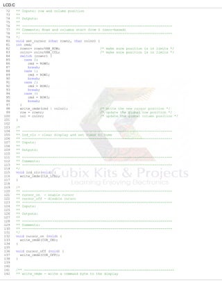
1 #include<P89V51Rx2.H>
2 static void write_cmde (unsigned char cmde);
3 static char check_busy_flag (void);
4 static void write_nibble (unsigned char nibble);
5 static void putlcd (unsigned char disp_data);
6 void put_char (char c) ;
7
8 #define LCD_PORT P1 /* LCD port definition */
9 sbit RS_PORT = P1^6;
10 sbit RW_PORT = P1^5;
11 sbit E_PORT = P1^4;
12
13 #define LCD_DAT_MSK 0x0F /* data bus mask */
14 #define BF_BIT 0x08 /* busy flag mask */
15
16 #define NB_ROW 0x04 /* 4 display lines */
17 #define NB_COL 0x10 /* 16 characters per line */
18
19 /*
20 Controller commands
21 */
22 #define ROW0 0x80 /* row 0 command */
23 #define ROW1 0xC0 /* row 1 command */
24 #define ROW2 0x90 /* row 2 command */
25 #define ROW3 0xD0 /* row 3 command */
26 #define CG_RAM 0x40 /* character graphic RAM command */
27 #define DD_RAM 0x80 /* data display RAM command */
28 #define CLR_LCD 0x01 /* clear LCD command */
29 #define CUR_ON 0x0F /* cursor ON command */
30 #define CUR_OFF 0x0C /* cursor OFF command */
31
32
33
34 #define C_R 0x0D
35 #define L_F 0x0A
36 #define B_S 0x08
37
38 /*
39 ** Definitions
40 */
41 static int row=0, col=0; /* save the current cursor position */
42
43 /*
44 ** ---------------------------------------------------------------------------
45 ** lcd_init - LCD controller initialization and configuration routine
46 ** ---------------------------------------------------------------------------
47 ** Inputs:
48 **
49 ** Outputs:
50 **
51 ** ---------------------------------------------------------------------------
52 ** Comments: This function is called once to initialize the LCD display.
53 ** The HD44780 controller contains 8 RAM loactions where user
54 ** characters can be defined.
55 ** Four of those locations are used in the example to define
56 ** the local symbols å, Ö, Ä and Å used from the function lcd_preter
57 ** ---------------------------------------------------------------------------
58 */
59 void lcd_init (void) {
60 char i;
61 static const char code initdata[] = {0x30, 0x30, 0X30,0X20, 0x28, 0x04, 0x06, 0x01};
62
63 for (i = 0; i < sizeof initdata; ++i) {
64 write_cmde(initdata[i]); /* write init data to the controller */
65
66 }
67 }
68
69 /** ---------------------------------------------------------------------------
70 ** set_cursor - set the cursor position
71 ** ---------------------------------------------------------------------------](https://image.slidesharecdn.com/experiment-16x2parallellcd-190129164251/85/Experiment-16-x2-parallel-lcd-5-320.jpg)
![LCD.C
285 **
286 ** Outputs:
287 **
288 ** ---------------------------------------------------------------------------
289 ** Comments: invoked from lcd_preter
290 ** ---------------------------------------------------------------------------
291 */
292
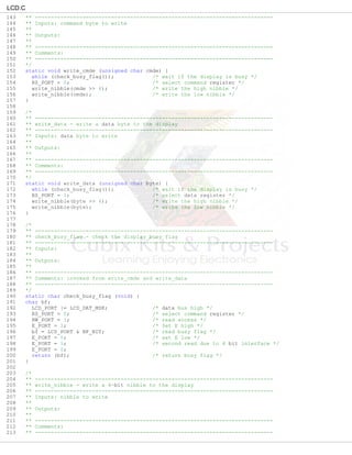
293 static void putlcd (unsigned char disp_data) {
294 if (col<NB_COL && col>=0) { /* check if we are inside the limits */
295 write_data(disp_data); /* write the character to the display */
296 col++; /* update the column position */
297 }
298 }
299 //====================================================================================================
=======
300
301
302 void put_string_lcd(char* dat)
303 {
304 int j=0;
305
306
307 while( dat[j] != 0) // send string
308 {
309 put_char(dat[j]); // start sending one byte
310 j++;
311 }
312 }
313
314 unsigned char hextoascii(unsigned char value)
315 {
316 idata unsigned char add;
317 if (value>9)
318 {
319 add=0x37;
320 }
321 else
322 add=0x30;
323
324 return (value + add );
325 }
326
327
328
329 void put_char (char c)
330 {
331 lcd_preter(c); /* write the character to the display */
332 }
333
334 void clean_lcd(void)
335 {
336 set_cursor(0,0);
337 put_string_lcd(" ");
338 set_cursor(1,0);
339 put_string_lcd(" ");
340 }](https://image.slidesharecdn.com/experiment-16x2parallellcd-190129164251/85/Experiment-16-x2-parallel-lcd-9-320.jpg)


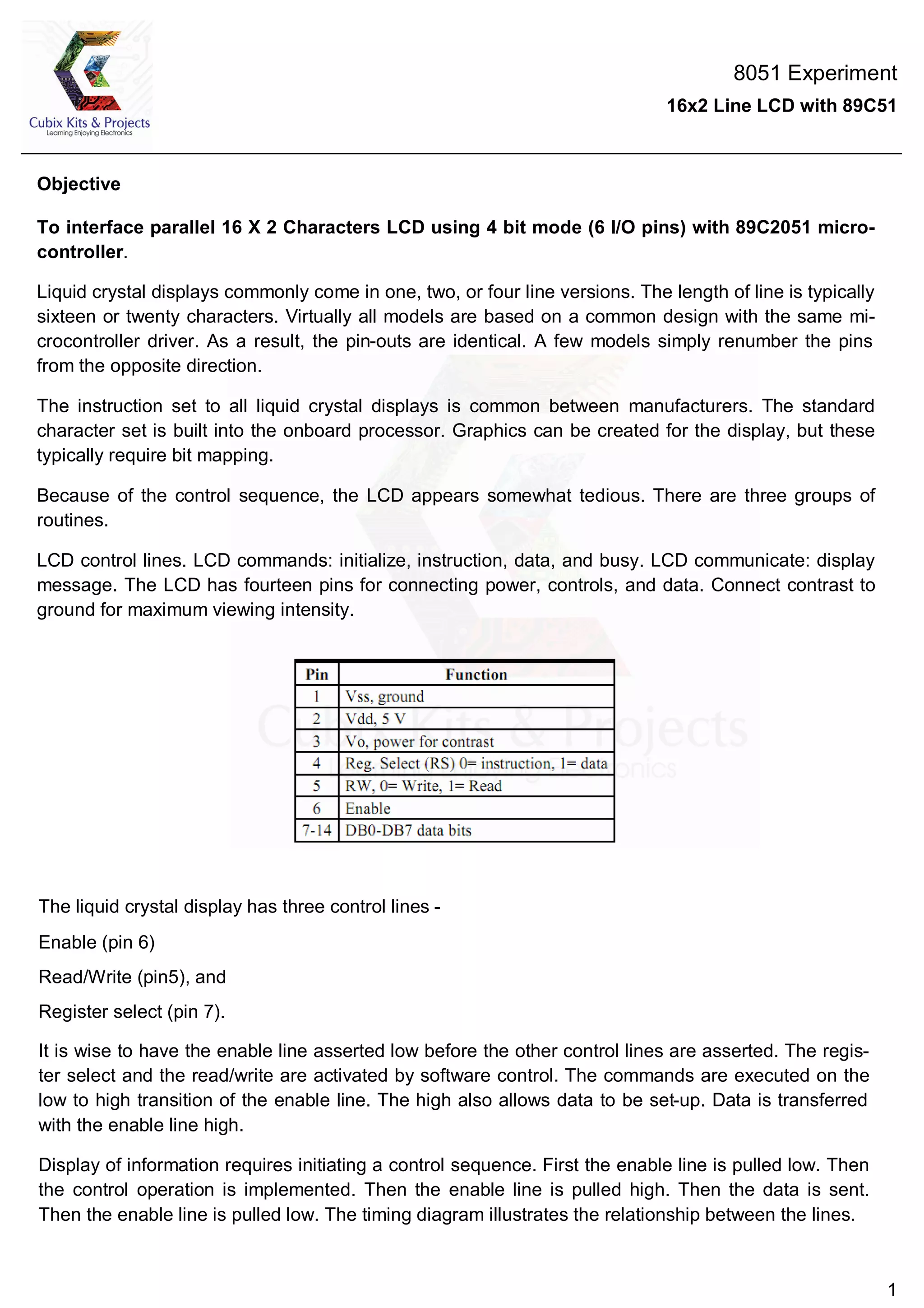
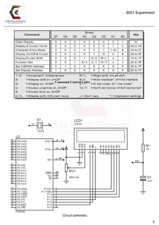
The document describes interfacing a 16x2 character LCD display with an 89C51 microcontroller using a 4-bit interface with 6 I/O pins. It includes the objective, background on LCD displays, control sequences, circuit schematic, command codes, and code files for initializing and writing to the LCD.


