Download to read offline
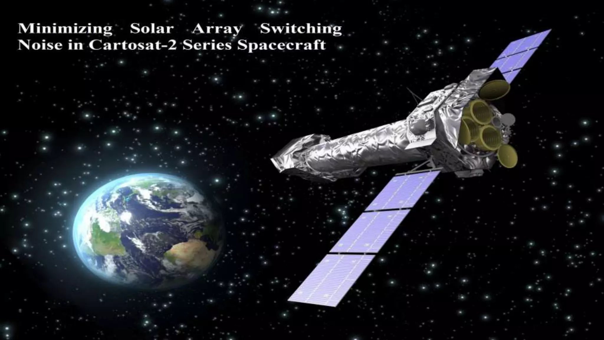


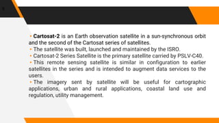


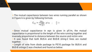
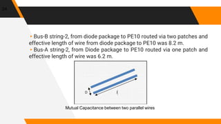

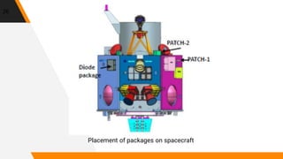
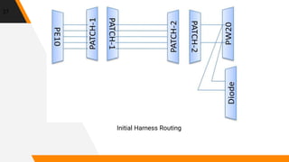
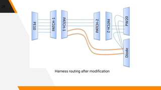


This presentation discusses an anomaly encountered during the Cartosat-2C Earth observation satellite program. Testing revealed that switching noise from one of the satellite's solar array strings was coupling onto signal lines and preventing commands from being executed properly. Analysis showed the noise coupling was due to a long wire harness routing both strings in close proximity. To address this, the harness routing was modified to reduce the shared wire length from 8.2m to 4.2m, eliminating the noise coupling issue. The satellite was then successfully launched with on-orbit performance meeting specifications.