4
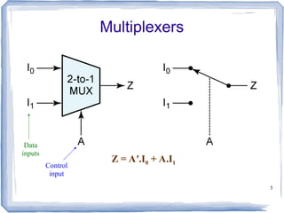
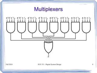
Multiplexers
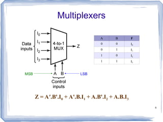
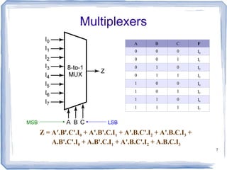
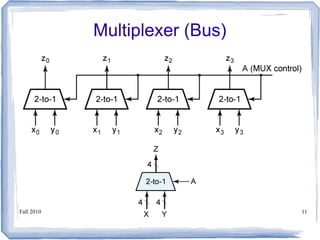
A multiplexer has
N control inputs
2N
data inputs
1 output
A multiplexer routes (or connects) the selected
data input to the output.
The value of the control inputs determines the
data input that is selected.
13
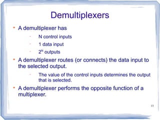
Demultiplexers
A demultiplexer has
N control inputs
1 data input
2N
outputs
A demultiplexer routes (or connects) the data input to
the selected output.
The value of the control inputs determines the output
that is selected.
A demultiplexer performs the opposite function of a
multiplexer.
14.
14
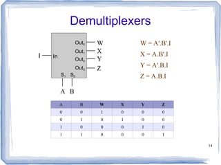
Demultiplexers
A B WX Y Z
0 0 I 0 0 0
0 1 0 I 0 0
1 0 0 0 I 0
1 1 0 0 0 I
W = A'.B'.I
X = A.B'.I
Y = A'.B.I
Z = A.B.I
Out0
In
S1 S0
I
W
X
Y
Z
A B
Out1
Out2
Out3
16
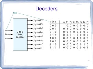
Decoders
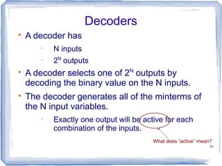
A decoder has
N inputs
2N
outputs
A decoder selects one of 2N
outputs by
decoding the binary value on the N inputs.
The decoder generates all of the minterms of
the N input variables.
Exactly one output will be active for each
combination of the inputs.
What does “active” mean?
17.
17
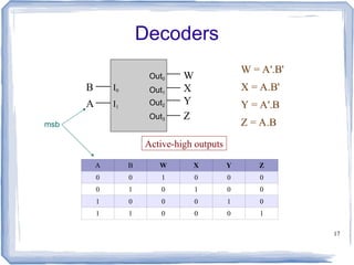
Decoders
A B WX Y Z
0 0 1 0 0 0
0 1 0 1 0 0
1 0 0 0 1 0
1 1 0 0 0 1
Active-high outputs
B
W
X
Y
Z
I0
I1
A
Out0
Out1
Out2
Out3
W = A'.B'
X = A.B'
Y = A'.B
Z = A.B
msb
18.
Fall 2010 ECE331 - Digital System Design 18
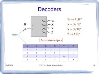
Decoders
A B W X Y Z
0 0 0 1 1 1
0 1 1 0 1 1
1 0 1 1 0 1
1 1 1 1 1 0
Active-low outputs
W = (A'.B')'
X = (A.B')'
Y = (A'.B)'
Z = (A.B)'
msb
B
W
X
Y
Z
I0
I1
A
Out0
Out1
Out2
Out3
20
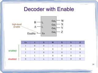
Decoder with Enable
EnA B W X Y Z
1 0 0 1 0 0 0
1 0 1 0 1 0 0
1 1 0 0 0 1 0
1 1 1 0 0 0 1
0 x x 0 0 0 0
enabled
disabled
high-level
enable
Enable
B
W
X
Y
Z
I0
I1
A
Out0
Out1
Out2
Out3
En
21.
21
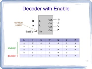
Decoder with Enable
EnA B W X Y Z
0 0 0 1 0 0 0
0 0 1 0 1 0 0
0 1 0 0 0 1 0
0 1 1 0 0 0 1
1 x x 0 0 0 0
enabled
disabled
Enable
B
W
X
Y
Z
I0
I1
A
Out0
Out1
Out2
Out3
En
low-level
enable
24
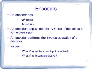
Encoders
An encoder has
2N
inputs
N outputs
An encoder outputs the binary value of the selected
(or active) input.
An encoder performs the inverse operation of a
decoder.
Issues
What if more than one input is active?
What if no inputs are active?
25.
25
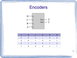
Encoders
A B CD Y Z
0 0 0 1 0 0
0 0 1 0 0 1
0 1 0 0 1 0
1 0 0 0 1 1
D
Z
Y
I0
I1
C
B I2
I3
A
Out0
Out1
26.
26
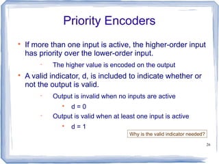
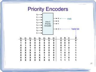
Priority Encoders
If morethan one input is active, the higher-order input
has priority over the lower-order input.
The higher value is encoded on the output
A valid indicator, d, is included to indicate whether or
not the output is valid.
Output is invalid when no inputs are active
d = 0
Output is valid when at least one input is active
d = 1
Why is the valid indicator needed?
29
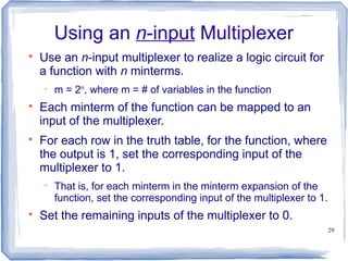
Using an n-inputMultiplexer
Use an n-input multiplexer to realize a logic circuit for
a function with n minterms.
m = 2n
, where m = # of variables in the function
Each minterm of the function can be mapped to an
input of the multiplexer.
For each row in the truth table, for the function, where
the output is 1, set the corresponding input of the
multiplexer to 1.
That is, for each minterm in the minterm expansion of the
function, set the corresponding input of the multiplexer to 1.
Set the remaining inputs of the multiplexer to 0.
30.
30
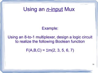
Using an n-inputMux
Example:
Using an 8-to-1 multiplexer, design a logic circuit
to realize the following Boolean function
F(A,B,C) = m(2, 3, 5, 6, 7)
31.
31
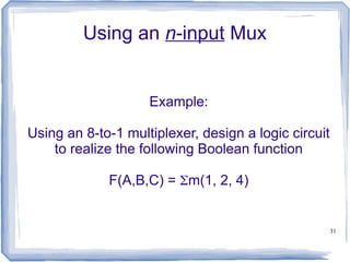
Using an n-inputMux
Example:
Using an 8-to-1 multiplexer, design a logic circuit
to realize the following Boolean function
F(A,B,C) = m(1, 2, 4)
32.
32
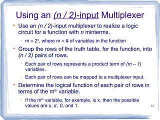
Using an (n/ 2)-input Multiplexer
Use an (n / 2)-input multiplexer to realize a logic
circuit for a function with n minterms.
m = 2n
, where m = # of variables in the function
Group the rows of the truth table, for the function, into
(n / 2) pairs of rows.
Each pair of rows represents a product term of (m – 1)
variables.
Each pair of rows can be mapped to a multiplexer input.
Determine the logical function of each pair of rows in
terms of the mth
variable.
If the mth
variable, for example, is x, then the possible
values are x, x', 0, and 1.
33.
33
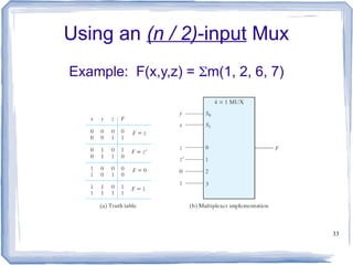
Using an (n/ 2)-input Mux
Example: F(x,y,z) = m(1, 2, 6, 7)
34.
34
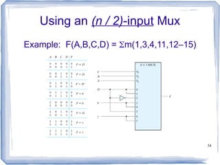
Using an (n/ 2)-input Mux
Example: F(A,B,C,D) = m(1,3,4,11,12–15)
35.
35
Using an (n/ 4)-input Mux
The design of a logic circuit using an (n / 2)-input
multiplexer can be easily extended to the use of
an (n / 4)-input multiplexer.
37
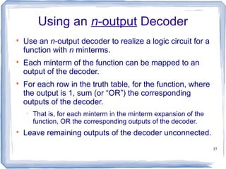
Using an n-outputDecoder
Use an n-output decoder to realize a logic circuit for a
function with n minterms.
Each minterm of the function can be mapped to an
output of the decoder.
For each row in the truth table, for the function, where
the output is 1, sum (or “OR”) the corresponding
outputs of the decoder.
That is, for each minterm in the minterm expansion of the
function, OR the corresponding outputs of the decoder.
Leave remaining outputs of the decoder unconnected.
38.
38
Using an n-outputDecoder
Example:
Using a 3-to-8 decoder, design a logic circuit to
realize the following Boolean function
F(A,B,C) = m(2, 3, 5, 6, 7)
39.
39
Using an n-outputDecoder
Example:
Using two 2-to-4 decoders, design a logic circuit
to realize the following Boolean function
F(A,B,C) = m(0, 1, 4, 6, 7)