Motion Based LEDController
Submitted by :-
1.Ravikiran Tirgule
2.Yogesh Yemul
3.Samarth Gundu
Photo of complete project
An IoT Project Using Arduino
2.
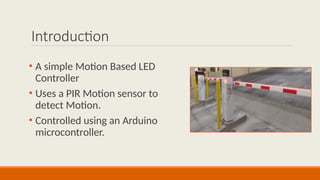
Introduction
• A simpleMotion Based LED
Controller
• Uses a PIR Motion sensor to
detect Motion.
• Controlled using an Arduino
microcontroller.
3.
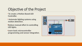
Objective of theProject
• To create a Motion Based LED
Controller.
• Automate lighting systems using
motion detection.
•Reduce manual effort in controlling
LED lights.
•Learn basic microcontroller
programming and sensor integration.
4.
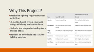
Why This Project?
•Traditionallighting requires manual
switching.
• A motion-based system improves
energy efficiency and convenience.
• Helps in learning embedded systems
and IoT basics.
•Provides an affordable and scalable
lighting solution.
Factor Manual Toll Gate Automated Toll Gate
Time
Efficiency
Slow, requires human
intervention
Fast, automatic
detection and
operation
Accuracy Prone to human errors
High accuracy with
sensor-based detection
Cost Requires staff salary
Initial setup cost, but
lower operational cost
Security
Manual verification, potential
for errors
Can integrate RFID or
cameras for better
security
Scalability
Difficult to scale with more
lanes
Easily scalable with
additional sensors
User
Convenience
May require manual ticketing or
payment
Contactless, quick
access
5.
Components Used
Arduino Uno– Microcontroller
for processing.
Ultrasonic Sensor (HC-SR04) –
Detects vehicles.
Servo Motor (SG90) – Lifts the
gate.
Breadboard & Jumper Wires –
Connect components.
Power Supply (Battery/USB) –
Powers the system.
6.
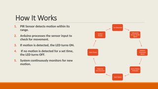
How It Works
1.PIR Sensor detects motion within its
range.
2. Arduino processes the sensor input to
check for movement.
3. If motion is detected, the LED turns ON.
4. If no motion is detected for a set time,
the LED turns OFF.
5. System continuously monitors for new
motion.
Car Detected
Ultrasonic
Sensor Sends
Signal
Arduino
Processes
Signal
Servo Motor
Activates
Gate Opens
Waits for
Few Seconds
Gate Closes
System
Resets
7.
Benefits & Applications
Benefitsof Motion-Based LED Controller
Easy Automation: Simple setup with minimal hardware.
Energy Efficient: Reduces power consumption by turning LEDs on only when needed.
Convenient: Eliminates the need for manual switching.
Learning Tool: Helps students and hobbyists understand IoT and automation basics.
Applications of Motion-Based LED Controller
Smart Home Lighting – Automates room lighting based on movement.
Hallways & Staircases – Lights up pathways only when motion is detected.
Restrooms & Offices – Ensures lights turn off when unoccupied.
Street Lights – Saves energy by activating only when people or vehicles are nearby.
8.
Challenges Faced
• FalseTriggers: Avoiding activation due to pets, airflow, or sudden light changes.
•Sensor Accuracy: Ensuring precise motion detection within the desired range.
•Response Time: Minimizing delay in turning the LED on/off after detecting motion.
•Detection Range Limitation: Adjusting sensor sensitivity to avoid detecting motion too far or too
close.
• Environmental Interference: Reducing the impact of temperature, humidity, and obstacles on
sensor performance.
9.
Conclusion & FutureImprovements
The project successfully demonstrates a simple motion-based LED controller using a PIR sensor and Arduino. It
automates lighting by detecting motion, reducing manual effort and energy consumption. This system is cost-
effective, easy to implement, and suitable for various applications like smart homes, offices, and security lighting.
Future Improvements :
Adjustable Sensitivity: Enhancing PIR sensor accuracy to reduce false triggers.
Timer-Based Control: Adding a delay function to keep the LED on for a set duration before turning off.
Smart Integration: Connecting the system with IoT platforms for remote monitoring and control.
Solar Power: Using renewable energy sources to make the system more energy-efficient.
Multiple Sensor Setup: Expanding coverage by integrating multiple PIR sensors for better motion detection.