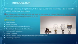
POWER ELECTRONICS ASPECTS FOR
SMART LED LIGHTING
OUTLINE
 INTRODUCTION
 RECENT TRENDS IN POWER ELECTRONICS
 POWER ELECTRONICS FOR LED TECHNOLOGIES
 SMART LIGHTING SYSTEM
 FUTURE SCOPE
 SUMMARY
INTRODUCTION
For high efficiency, long lifetime, better light quality and reliability, LED is already a
winner in lighting technology.
An efficacy of 200 LPW of LED will lead to decrease in Global Electricity use of about
13% and Global CO2 Emissions of 2.3%
Advantages
• Long Lifespan.
• Energy Efficiency.
• Improved Environmental Performance.
• The Ability to Operate in Cold Conditions.
• No Heat or UV Emissions.
• Design Flexibility.
• Instant Lighting and the Ability to Withstand Frequent Switching.
• Low Voltage Operation.
COMPARATIVE ANALYSIS
CHARACTERISTICS OF LIGHT
• Colour temperature
•Warm white- living room ,bed room
• Cool white- kitchen,studyroom,office
retails
• Day light- Commercial , Retails, Art
studio
• CRI-
• This measure how realistic or natural the
light illuminated by the light
RECENT TRENDS IN POWER ELECTRONICS
LED DRIVER –
•
•LEDS CANNOT BE DRIVEN DIRECTLY FROM THE ALTERNATING CURRENT (AC).
THEREFORE, AN LED POWER SUPPLY IS REQUIRED TO CONVERT HIGH
VOLTAGE-ALTERNATING CURRENT TO LOW VOLTAGE-DIRECT CURRENT.
FLY BACK CONVERTER, FORWARD CONVERTER,
RESONANT CONVERTER
DC DC CONVERTER
• TRADITIONALLY LED DRIVER CIRCUIT USED DC-DC CONVERTERS SUCH AS BUCK, BOOST
AND BUCK-BOOST CONVERTER, BUT THIS CIRCUIT HAS TO PROCESS A LOT OF POWER.
THIS DRAWBACK IS ELIMINATED BY FLY-BACK CONVERTER. THE FLY-BACK CONVERTER IS USED AS DRIVER
CIRCUIT BECAUSE IT HASADVANTAGES OF USING LEAST COMPONENTS, TRANSFORMER WORKS AS INDUCTIVE
FILTER, LOW COST AND IS TYPICALLY USED FOR LOW POWER APPLICATIONS
PROGRAMMABLE LED DRIVE—
S THE INTERNET OF THINGS (IOT) CONTINUES TO GAIN MOMENTUM IN THE SMART LIGHTING SYSTEM, LED DRIVERS HAVE BECOME
IMPORTANT TOOLS THAT CAN BE CONNECTED TO SENSORS FOR VARIOUS PURPOSES. THEY CAN BE USED FOR COLLECTING DATA,
CONTROLLING A SINGLE OR MULTIPLE FIXTURES, ETC.
LED DRIVER
• In simplest terms, an LED driver runs the LED
light. It is a power supply that's typically self-
contained, and its one job is to regulate all of the
power an LED light needs
• It is an interface between the AC supply line and the
LEDs, converting 110V/220V 50Hz/60Hz AC into DC
regulated current. Conventional light sources like bulbs
work on AC power but LEDs work on DC input as the
diodes have polarity.
• Besides, it also acts as an interface that
integrates sensors and wireless communication
modules to enable human-machine interaction for
various smart lighting applications.
LED DRIVER BLOCK DIAGRAM
INPUT
FILTER
PFC
CONVERTE
R
(SEPIC/TOT
EMPOLE)
(OPTIONAL
)
DC-DC
STAGE
(FLYBACK/
RESONANT
)
LED
RECTIFIE
R UNIT
WIRED OR
WIRELESS
LIGHTING
NETWORK
(Zigbee,PLC,DALI,B
LE)
CONT.
• SINGLE STAGE LED DRIVE --( Multistring low voltage high current density >200 W LED Load)
Target application high CRI and CCT application like video walls, high resolution TV, movies ,
projections, Gaming
• TWO STAGE LED DRIVE-- (Multistring low voltage high current density 100W- 200W LED Load)
Target application relatively CRI and CCT compromised like LED TV, High lumen lighting
• THREE STAGE LED DRIVE— (Single LED string <100W)
Target application general illumination, street lighting etc.
• Traditionally LED driver circuit used DC-DC converters such as buck, boost and buck-boost converter,
but this circuit has to process a lot of Power. This drawback is eliminated by Fly back converter,
Resonant converter.
AUTOMATIC POWER FACTOR CORRECTION
Many SMPS without power-factor correction (PFC) draw higher current than a corrected
SMPS, so at power levels above 70 W, legislation requires designers to incorporate circuitry to
correct PF to a value close to unity. The most common technique for active PFC uses a boost
converter to convert rectified mains to a high DC level and then to use pulse-width
modulation (PWM) to regulate the DC level.
1. totem-pole PFC technique
2. single ended primary inductance converter (SEPIC) fed power factor correction
CONT.
• Different lighting applications require different wattages of LED strings driven by
a driver of specific voltage and current ratings. Thus each LED fixture is powered
by a compatible driver of corresponding wattage. In case of incompatibility, the
circuit maybe damaged due to higher current or voltage application or the light
may start flickering too. In order to avoid any such problems, it is beneficial to
have a single driver compatible with all the LED light fixtures.
DIGITAL POWER SUPPLY
WIDE BAND GAP SEMICONDUCTOR
Silicon carbide (SiC) and Gallium nitride (GaN).
• These highly innovative materials belong to the wide-bandgap (WBG) family of
semiconductors.
• WBG devices also provide lower on-resistance, higher breakdown voltage, and higher short-
and long-term reliability. The breakdown electric field of WBG semiconductors allows lower
leakage current and higher operating voltages.
• Silicon has a bandgap of 1.12 electron-volts; gallium arsenide, 1.4 eV; silicon carbide, 2.86
eV; and gallium nitride, 3.4 eV.
• The higher electron mobility of SiC and GaN compared with silicon enables devices built with
those WBG materials to operate at higher switching speeds. The wide-bandgap materials
allow reduced energy consumption. The reduction in energy dissipated as heat not only cuts
power losses but also enables smaller systems, reducing costs compared with silicon
solutions
CONT.
SiC(Silicon Carbide)-
• Owing to the intrinsic material advantages of SiC over Silicon(Si), Sic powered
device can operate at higher voltage, higher switching frequency,higher
temperature.
• Because of its high melting point and high thermal conductivity, SiC can operate at
higher temperatures than silicon. SiC is preferred in power applications with high
voltage and current values.
GaN (Gallium Nitride)-
• GaN remains the leading material for radio-frequency fields in which the voltages donot
reach very high values but the breakdown electric fields are higher.
SMART LIGHTING SYSTEM
SMART OUTDOOR LIGHTING SYSTEM
• IMAGE PROCESSOR
• AUTOMATIC ON/OFF
• SOLAR BASED LIGHTING SYSTEM-
SMART INDOOR LIGHTING
• DALI
• HUMANCENTRIC LIGHT
• WIIRELESS LIGHTING(BLE ,BASED SMART HOME LIGHTING SYSTEM)
IOT -ENABLED SMART LIGHTING SYSTEMS
Long-range Communication:
• Long-range communication in the context of SLS usually refers to information sharing between LCUs and
CC and also between LCUs.
Hence, a long-range communication protocol is needed to establish a communication
channel to connect LCUs and CC. Protocols such as Wi-Fi, Ethernet, GPRS, WiMax, 3G/4G/5G
are utilized to establish communication channels between LCUs and CC.
Short-range Communication:
• For an Smart lighting system(SLS), distances between Lamp units and corresponding Lamp
control units are in small range (less than 100meters). Short-range protocols are utilized to
provide a communication mainly between the LCUs and LUs in an SLS.
• Short-range protocols can be both wired (e.g., DALI andwireless (e.g., ZigBee , JenNET-IP ,
6LoWPAN)
SOLAR BASED STREET LIGHTING SYSTEM
For solar lighting purpose MPPT scheme are used to
charge the battery during day time. MPPT scheme is
the major scheme for charging the battery
AC-DC led driver are used for back up charging
scheme in case of unavailability of battery
High efficiency led driver are used by using efficient
Mosfet and gate driver ICS.
Using 6LoWPAN mesh technology the straight light
nodes communicate with each other.6Lowpan provide
higher data rate than other wireless protocol.
The data concentrator unit(DCU) on board global
system for mobile communication to communicate
with cloud application
Automatic on/off /dimming of light can be achieve
sensing ambient and movement.
COMMUNICATION STAGES
1
Access Point
(NODE)
This is the radio that
is receiving data
from one or more
end points and is
usually connected to
the internet
End point
(DCU)
It is a device which
operate through its
sensor data , it’s
ability to remotely
controlled
Back end
(SERVER)
Once wireless data
gets to the access
point, it is generally
sent to the server
over internet ,”The
cloud-where the
program is running.
PROGRAMMABLE LED DRIVE
FUTURE SCOPE
LIFI TECHNOLOGY
IMAGE PROCESSING LIGHT SYSTEM
AI APPLICATION IN LIGHTING TECHNOLOGY

SMART POWER ELECRONICS FOR LED LIGHTS APPLICATION.pptx

  • 1.
    POWER ELECTRONICS ASPECTSFOR SMART LED LIGHTING
  • 2.
    OUTLINE  INTRODUCTION  RECENTTRENDS IN POWER ELECTRONICS  POWER ELECTRONICS FOR LED TECHNOLOGIES  SMART LIGHTING SYSTEM  FUTURE SCOPE  SUMMARY
  • 3.
    INTRODUCTION For high efficiency,long lifetime, better light quality and reliability, LED is already a winner in lighting technology. An efficacy of 200 LPW of LED will lead to decrease in Global Electricity use of about 13% and Global CO2 Emissions of 2.3% Advantages • Long Lifespan. • Energy Efficiency. • Improved Environmental Performance. • The Ability to Operate in Cold Conditions. • No Heat or UV Emissions. • Design Flexibility. • Instant Lighting and the Ability to Withstand Frequent Switching. • Low Voltage Operation.
  • 4.
  • 5.
    CHARACTERISTICS OF LIGHT •Colour temperature •Warm white- living room ,bed room • Cool white- kitchen,studyroom,office retails • Day light- Commercial , Retails, Art studio • CRI- • This measure how realistic or natural the light illuminated by the light
  • 6.
    RECENT TRENDS INPOWER ELECTRONICS LED DRIVER – • •LEDS CANNOT BE DRIVEN DIRECTLY FROM THE ALTERNATING CURRENT (AC). THEREFORE, AN LED POWER SUPPLY IS REQUIRED TO CONVERT HIGH VOLTAGE-ALTERNATING CURRENT TO LOW VOLTAGE-DIRECT CURRENT. FLY BACK CONVERTER, FORWARD CONVERTER, RESONANT CONVERTER DC DC CONVERTER • TRADITIONALLY LED DRIVER CIRCUIT USED DC-DC CONVERTERS SUCH AS BUCK, BOOST AND BUCK-BOOST CONVERTER, BUT THIS CIRCUIT HAS TO PROCESS A LOT OF POWER. THIS DRAWBACK IS ELIMINATED BY FLY-BACK CONVERTER. THE FLY-BACK CONVERTER IS USED AS DRIVER CIRCUIT BECAUSE IT HASADVANTAGES OF USING LEAST COMPONENTS, TRANSFORMER WORKS AS INDUCTIVE FILTER, LOW COST AND IS TYPICALLY USED FOR LOW POWER APPLICATIONS PROGRAMMABLE LED DRIVE— S THE INTERNET OF THINGS (IOT) CONTINUES TO GAIN MOMENTUM IN THE SMART LIGHTING SYSTEM, LED DRIVERS HAVE BECOME IMPORTANT TOOLS THAT CAN BE CONNECTED TO SENSORS FOR VARIOUS PURPOSES. THEY CAN BE USED FOR COLLECTING DATA, CONTROLLING A SINGLE OR MULTIPLE FIXTURES, ETC.
  • 7.
    LED DRIVER • Insimplest terms, an LED driver runs the LED light. It is a power supply that's typically self- contained, and its one job is to regulate all of the power an LED light needs • It is an interface between the AC supply line and the LEDs, converting 110V/220V 50Hz/60Hz AC into DC regulated current. Conventional light sources like bulbs work on AC power but LEDs work on DC input as the diodes have polarity. • Besides, it also acts as an interface that integrates sensors and wireless communication modules to enable human-machine interaction for various smart lighting applications.
  • 8.
    LED DRIVER BLOCKDIAGRAM INPUT FILTER PFC CONVERTE R (SEPIC/TOT EMPOLE) (OPTIONAL ) DC-DC STAGE (FLYBACK/ RESONANT ) LED RECTIFIE R UNIT WIRED OR WIRELESS LIGHTING NETWORK (Zigbee,PLC,DALI,B LE)
  • 9.
    CONT. • SINGLE STAGELED DRIVE --( Multistring low voltage high current density >200 W LED Load) Target application high CRI and CCT application like video walls, high resolution TV, movies , projections, Gaming • TWO STAGE LED DRIVE-- (Multistring low voltage high current density 100W- 200W LED Load) Target application relatively CRI and CCT compromised like LED TV, High lumen lighting • THREE STAGE LED DRIVE— (Single LED string <100W) Target application general illumination, street lighting etc. • Traditionally LED driver circuit used DC-DC converters such as buck, boost and buck-boost converter, but this circuit has to process a lot of Power. This drawback is eliminated by Fly back converter, Resonant converter.
  • 10.
    AUTOMATIC POWER FACTORCORRECTION Many SMPS without power-factor correction (PFC) draw higher current than a corrected SMPS, so at power levels above 70 W, legislation requires designers to incorporate circuitry to correct PF to a value close to unity. The most common technique for active PFC uses a boost converter to convert rectified mains to a high DC level and then to use pulse-width modulation (PWM) to regulate the DC level. 1. totem-pole PFC technique 2. single ended primary inductance converter (SEPIC) fed power factor correction
  • 11.
    CONT. • Different lightingapplications require different wattages of LED strings driven by a driver of specific voltage and current ratings. Thus each LED fixture is powered by a compatible driver of corresponding wattage. In case of incompatibility, the circuit maybe damaged due to higher current or voltage application or the light may start flickering too. In order to avoid any such problems, it is beneficial to have a single driver compatible with all the LED light fixtures.
  • 12.
  • 13.
    WIDE BAND GAPSEMICONDUCTOR Silicon carbide (SiC) and Gallium nitride (GaN). • These highly innovative materials belong to the wide-bandgap (WBG) family of semiconductors. • WBG devices also provide lower on-resistance, higher breakdown voltage, and higher short- and long-term reliability. The breakdown electric field of WBG semiconductors allows lower leakage current and higher operating voltages. • Silicon has a bandgap of 1.12 electron-volts; gallium arsenide, 1.4 eV; silicon carbide, 2.86 eV; and gallium nitride, 3.4 eV. • The higher electron mobility of SiC and GaN compared with silicon enables devices built with those WBG materials to operate at higher switching speeds. The wide-bandgap materials allow reduced energy consumption. The reduction in energy dissipated as heat not only cuts power losses but also enables smaller systems, reducing costs compared with silicon solutions
  • 14.
    CONT. SiC(Silicon Carbide)- • Owingto the intrinsic material advantages of SiC over Silicon(Si), Sic powered device can operate at higher voltage, higher switching frequency,higher temperature. • Because of its high melting point and high thermal conductivity, SiC can operate at higher temperatures than silicon. SiC is preferred in power applications with high voltage and current values. GaN (Gallium Nitride)- • GaN remains the leading material for radio-frequency fields in which the voltages donot reach very high values but the breakdown electric fields are higher.
  • 15.
    SMART LIGHTING SYSTEM SMARTOUTDOOR LIGHTING SYSTEM • IMAGE PROCESSOR • AUTOMATIC ON/OFF • SOLAR BASED LIGHTING SYSTEM- SMART INDOOR LIGHTING • DALI • HUMANCENTRIC LIGHT • WIIRELESS LIGHTING(BLE ,BASED SMART HOME LIGHTING SYSTEM)
  • 16.
    IOT -ENABLED SMARTLIGHTING SYSTEMS Long-range Communication: • Long-range communication in the context of SLS usually refers to information sharing between LCUs and CC and also between LCUs. Hence, a long-range communication protocol is needed to establish a communication channel to connect LCUs and CC. Protocols such as Wi-Fi, Ethernet, GPRS, WiMax, 3G/4G/5G are utilized to establish communication channels between LCUs and CC. Short-range Communication: • For an Smart lighting system(SLS), distances between Lamp units and corresponding Lamp control units are in small range (less than 100meters). Short-range protocols are utilized to provide a communication mainly between the LCUs and LUs in an SLS. • Short-range protocols can be both wired (e.g., DALI andwireless (e.g., ZigBee , JenNET-IP , 6LoWPAN)
  • 17.
    SOLAR BASED STREETLIGHTING SYSTEM For solar lighting purpose MPPT scheme are used to charge the battery during day time. MPPT scheme is the major scheme for charging the battery AC-DC led driver are used for back up charging scheme in case of unavailability of battery High efficiency led driver are used by using efficient Mosfet and gate driver ICS. Using 6LoWPAN mesh technology the straight light nodes communicate with each other.6Lowpan provide higher data rate than other wireless protocol. The data concentrator unit(DCU) on board global system for mobile communication to communicate with cloud application Automatic on/off /dimming of light can be achieve sensing ambient and movement.
  • 18.
    COMMUNICATION STAGES 1 Access Point (NODE) Thisis the radio that is receiving data from one or more end points and is usually connected to the internet End point (DCU) It is a device which operate through its sensor data , it’s ability to remotely controlled Back end (SERVER) Once wireless data gets to the access point, it is generally sent to the server over internet ,”The cloud-where the program is running.
  • 19.
  • 21.
    FUTURE SCOPE LIFI TECHNOLOGY IMAGEPROCESSING LIGHT SYSTEM AI APPLICATION IN LIGHTING TECHNOLOGY