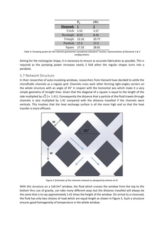
This document provides a theoretical development of a microfluidic insulation device for windows. It begins with a literature review of existing window insulation technologies such as single glazing, double glazing, triple glazing, and replacing the air gap with different gases. A microfluidic system is proposed that contains microchannels on the inner window surface to convect heat using flowing water. Calculations determine the optimal channel geometry and network, as well as pumps and valves. The system is estimated to provide a 29% energy savings for a 1m2 window section by reducing heat loss.


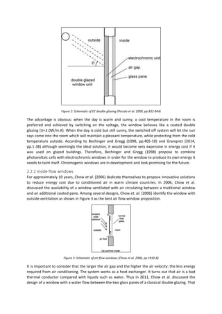
![were formed completely when the PDMS layers bonded to the glass window. The two designs are
called Diamond 1 and Diamond 2, having channel cross-sections (width by height) of 1 mm by 0.10
mm and 2 mm by 0.10 mm, respectively.
A pane of glass was heated using an incandescent light source (50 cm from the glass) to an initial
temperature ranging from 35 to 40°C. Water maintained at room temperature (RT, 21 1C) was then
pumped through the microvascular channels at flow rates of 0.20, 2.0 and 10 mL/min. Changes in
surface temperature were visualized using an IR camera as a function of the flow rate.
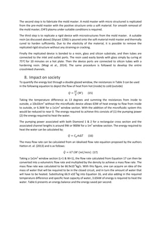
Taking from the results, it was found that a modest flow rate of 2.0 mL/min of RT water was able to
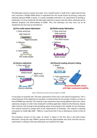
produce cooling from an average 37°C and 39°C to approximately 30°C for the 1 and 2 mm wide
channels of Diamond 1 and 2, respectively. The experimental results from the authors will be used to
quantify the heat transfer coefficient of such a micro-flow device, in aid to develop a thermal
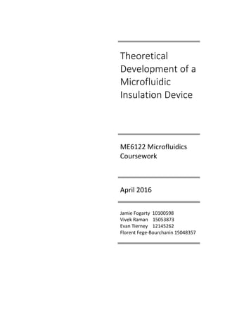
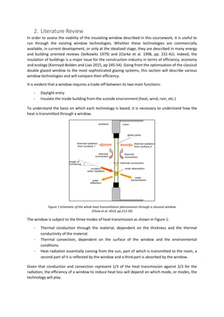
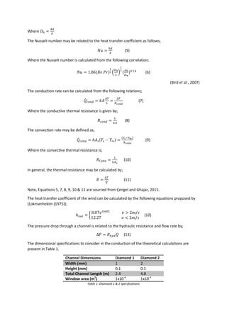
insulation micro-fluidic system. Figure 4 illustrates a schematic of the microfluidic device, its
positioning and also an image of the microfluidic device with and without water in the channels.
Figure 4: Microfluidic convective cooling system network (Hatton et. al., 2013). (A) Schematic of microfluidic device and it's
positioning. (B) Microfluidic device without water (LHS) and with water (RHS) in the channels.
5.1 Theory and Resistance Network
The next logical path, to ensure the reader understands the heat transfer mechanism, is to define
the theory used to quantify the potential for microfluidic insulation / heat transfer.
In order to acquire the total channel length in the zig-zag design, seen in Figure 1, it was necessary to
manipulate Pythagoras Theorem. The resulting equation is:
𝐿 = [∑ [4√2(𝑥 − 𝛿𝑛)2]
𝑥/𝛿
𝑛=0,1,2… ] − 2√𝑥2 (4)
Where L is the total channel length, x=width (or height, as it’s a square window), δ= channel spacing,
n is the number of channels defined as n=(x/δ)-1, (considering 0 as a integer i.e. 3 channels would
have a set n of {0, 1, 2}). The second factor accounts for the longest channel from diagonal to
diagonal, there may only be two in the network.
The Reynold’s number may be calculated by;
𝑅𝑒 =
𝜌𝑢𝐷ℎ
𝜇
(2)](https://image.slidesharecdn.com/a28ca856-cf7d-4ccd-b650-0c7f15855346-160727183552/85/Microfluidics_Final_Draft_Merge_Final_PDFPDF-14-320.jpg)
![References
Akbari, M. (2011) FLOW AND HEAT TRANSFER IN MICROFLUIDIC DEVICES WITH APPLICATION TO
OPTOTHERMAL ANALYTE PRECONCENTRATION AND MANIPULATION, DOCTOR OF PHILOSOPHY.
Baetens, R. Jelle, B.P. Gustavsen, A. (2010) ‘Properties, requirements and possibilities of smart
windows for dynamic daylight and solar energy control in buildings: A state-of-the-art review’, Solar
Energy Materials and Solar Cells, 94(2), 87-105, available: ScienceDirect [accessed 22/03/2016]
Bechinger, C. Gregg, B.A. (1998) ‘Development of a new self-powered electrochromic device for light
modulation without external power supply’, Solar Energy Materials and Solar Cells, 54(1-4), 405-410,
available: ScienceDirect [accessed 04/04/2016]
Beebe DJ, Mensing GA, Walker GM (2002) Physics and application of microfluidic in biology. Annu
Rev Biomed Eng 4:261–286
Bird, R., Stewart, W., Lightfoot, E. (2007) Transport Phenomena, J. Wiley: New York.
Bruus, H. (2008) Theoretical Microfluidics, Oxford University Press: Oxford.
Capretto, L., Cheng, W., Hill, M., Zhang, X. (2011) "Micromixing Within Microfluidic Devices",
Microfluidics, 27-68.
Çengel, Y.Ghajar, A. (2015) Heat And Mass Transfer, McGraw-Hill: New York, N.Y.
Chavez-Galan, J. Almanza, R. (2007) ‘Solar filters based on iron oxides used as efficient windows for
energy savings’ Solar Energy, 81(1), 13-19, available: ScienceDirect [accessed 04/04/2016]
Chow, T.T. Li, C. Lin, Z. (2010) ‘Innovative solar windows for cooling-demand climate’, Solar Energy
Materials and Solar Cells, 94(2), 212-220, available: ScienceDirect [accessed 20/02/2016]
Chow, T.T. Li, C. Lin, Z. (2011) ‘Thermal characteristics of water-flow double-pane window’
International Journal of Thermal Sciences, 50(2), 140-148, available: ScienceDirect [accessed
20/02/2016]
Chow, T.T. Lin, Z. He, W. Chan, A.L.S. Fong, K.F. (2006) ‘Use of ventilated solar screen window in
warm climate’, Applied Thermal Engineering, 26(16), 1910-1918, available: ScienceDirect [accessed
20/02/2016]
Clarke, J. A. Janak, M. Ruyssevelt, P. (1998) ‘Assessing the overall performance of advanced glazing
systems’ Solar Energy, 63(4), 231-241, available: ScienceDirect [accessed 25/03/2016]](https://image.slidesharecdn.com/a28ca856-cf7d-4ccd-b650-0c7f15855346-160727183552/85/Microfluidics_Final_Draft_Merge_Final_PDFPDF-31-320.jpg)
![Cuce, E. Cuce, P.M. (2016) ‘Vacuum glazing for highly insulating windows: Recent developments and
future prospects’ Renewable and Sustainable Energy Reviews, 54, 1345-1357, available:
ScienceDirect [accessed 16/04/2016]
D.B. Tuckerman and R.F. Pease, Optimized convective cooling using micromachined structure,
Journal of the Electrochemical Society 129, P. C 98 (1982).
Deb, S.K. (2008) ‘Opportunities and challenges in science and technology of WO3 for electrochromic
and related applications’, Solar Energy Materials and Solar Cells, 92(2), 245-258, available:
ScienceDirect [accessed 16/04/2016]
Electric Ireland Standard Domestic Elec | Bonkers.Ie [online] (2016) [online], Bonkers.ie.
Gardiner, D.J. Morris, S.M. Coles, H.J. (2009) ‘High-efficiency multistable switchable glazing using
smectic A liquid crystals’, Solar Energy Materials and Solar Cells, 93(3), 301-306, available:
ScienceDirect [accessed 15/04/2016]
Granqvist C.G. (2014) ‘Electrochromics for smart windows: Oxide-based thin films and devices’, Thin
Solid Films, 564, 1-38, available: ScienceDirect [accessed 16/04/2016]
Hardt, S., Schönfeld, F. (2007) Microfluidic Technologies For Miniaturized Analysis Systems, Springer:
New York, NY
Hatton, B., Wheeldon, I., Hancock, M., Kolle, M., Aizenberg, J., Ingber, D. (2013) "An artificial
vasculature for adaptive thermal control of windows", Solar Energy Materials and Solar Cells, 117,
429-436.
Hatton, B.D. Wheeldona, I. Hancockd, M.J. Kollea, M. Aizenberga, J. Ingbera, D.E. (2013) ‘An artificial
vasculature for adaptive thermal control of windows’, Solar Energy Materials and Solar Cells, 117,
429-436, available: ScienceDirect [accessed 11/02/2016]
Ismail, K. A.R. Salinas, C.T. Henriquez, J.R. (2008) ‘Comparison between PCM filled glass windows and
absorbing gas filled windows’, Energy and Buildings, 40(5), 710-719, available: ScienceDirect
[accessed 14/04/2016]
Kakaç, S. (2010) Microfluidics Based Microsystems, Springer: Dordrecht.
Konroyd-Bolden, E. Liao, Z. (2015) ‘Thermal window insulation’, Energy and Buildings, 109, 245-254,
available: ScienceDirect [accessed 15/04/2016]
LI, P. C. H. 2010. Fundamentals of MICROFLUIDICS AND LAB ON A CHIP FOR BIOLOGICAL ANALYSIS
AND DISCOVERY, Boca Raton, CRC Press.](https://image.slidesharecdn.com/a28ca856-cf7d-4ccd-b650-0c7f15855346-160727183552/85/Microfluidics_Final_Draft_Merge_Final_PDFPDF-32-320.jpg)
![Lin, B., Basuray, S. (2011) Microfluidics, Springer: Berlin.
Lokmanhekim, M. (ed.) (1975). Procedure for Determining Heating and Cooling Loads for
Computerizing Energy Calculations: Algorithms for Building Heat Transfer Subroutines, ASHRAE,
New-York
Lolli, N. Andresen, I. (2016) ‘Aerogel vs. argon insulation in windows: A greenhouse gas emissions
analysis’, Building and Environment, 101, 64-76, available: ScienceDirect [accessed 15/04/2016]
Macrelli, G. (1995) ‘Optical characterization of commercial large area liquid crystal devices’, Solar
Energy Materials and Solar Cells, 39(2-4), 123-131, available: ScienceDirect [accessed 15/04/2016]
Microfluidics And Microfluidic Devices: A Review - Elveflow [online] (2016) [online], Elveflow.
MOGI, K., SUGII, Y., YAMAMOTO, T. & FUJII, T. 2014. Rapid fabrication technique of
nano/microfluidic device with high mechanical stability utilizing two-step soft lithography. Sensors
and Actuators B: Chemical, 201, 407-412.
Moore, G., ‘’VLSI, What does the future hold,’’ Electron. Aust., Vol. 42., No. 14, 1980.
Morini, G. (2004) "Single-phase convective heat transfer in microchannels: a review of experimental
results", International Journal of Thermal Sciences, 43(7), 631-651.
Nguyen, N., Wereley, S. (2002) Fundamentals And Applications Of Microfluidics, Artech House:
Boston, MA.
Peterson, K. E., ‘’silicon as mechanical material,’’ Proceedings of the IEEE, Vol. 70, no. 5, 1982, pp.
420-457
Piccolo, A. Pennisi, A. Simone, F. (2009) ‘Daylighting performance of an electrochromic window in a
small scale test-cell’, Solar Energy, 83(6), 832-844, available: ScienceDirect [accessed 14/04/2016]
Qi, Y. Yin, X. Zhang, J. (2016) ‘Transparent and heat-insulation plasticized polyvinyl chloride (PVC)
thin film with solar spectrally selective property’, Solar Energy Materials and Solar Cells, 151, 30-35,
available: ScienceDirect [accessed 10/04/2016]
Rosseinsky, D.R. Mortimer, R.J. (2001) ‘Electrochromic Systems and the Prospects for Devices’,
Advanced Materials, 13(11), 783-793.
Selkowitz, S. (1979) ‘Thermal Performance of Insulating Windows Systems’, Ashrae, 85 part2(5)](https://image.slidesharecdn.com/a28ca856-cf7d-4ccd-b650-0c7f15855346-160727183552/85/Microfluidics_Final_Draft_Merge_Final_PDFPDF-33-320.jpg)
![Singh, M. C. Garg, S.N. Jha, R. (2008) ‘Different glazing systems and their impact on human thermal
comfort—Indian scenario’, Building and Environment, 43(10), 1596-1602, available: ScienceDirect
[accessed 17/04/2016]
Tian, W., Finehout, E. (2008) Microfluidics For Biological Applications, Springer Science + Business
Media: New York.
U.S. Department of Energy (Ed.), Buildings Energy Data Book, D&R International Ltd., Silver Spring,
MD, USA, 2009.
Wallentén, P. (2001) "Convective heat transfer coefficients in a full-scale room with and without
furniture", Building and Environment, 36(6), 743-751.
Warner, J.L. (1995) ‘Selecting Windows for Energy Efficiency’, Home Energy Magazine, available:
Home Energy Magazine [accessed 16/04/2016]
WASHE, A. P., LOZANO-SÁNCHEZ, P., BEJARANO-NOSAS, D., TEIXEIRA-DIAS, B. & KATAKIS, I. 2013.
Electrochemically actuated passive stop–go microvalves for flow control in microfluidic systems.
Microelectronic Engineering, 111, 416-420.
Weigl B, Bardell R, Cabrera C (2003) Lab-on-a-chip for drug development. Adv Drug Deliv Rev
55(3):349–37
Whitesides, G. (2006) "The origins and the future of microfluidics", Nature, 442(7101), 368-373.
Wittwer, V. Datz, M. Elle, J. Georg, A. Graf, W. Walze, G. (2004) ‘Gasochromic windows’, Solar Energy
Materials and Solar Cells, 84(1-4), 305-314, available: ScienceDirect [accessed 14/04/2016]
Yazicioglu, A., Kakaç, S. (2010) "Convective Heat Transfer in Microscale Slip Flow", Microfluidics
Based Microsystems, 15-38.
ZAHRA, A., SCIPINOTTI, R., CAPUTO, D., NASCETTI, A. & DE CESARE, G. 2015. Design and fabrication
of microfluidics system integrated with temperature actuated microvalve. Sensors and Actuators A:
Physical, 236, 206-213.](https://image.slidesharecdn.com/a28ca856-cf7d-4ccd-b650-0c7f15855346-160727183552/85/Microfluidics_Final_Draft_Merge_Final_PDFPDF-34-320.jpg)


