
Recommended
More Related Content
What's hot
What's hot (20)
Similar to Michanical actuators
Similar to Michanical actuators (20)
Recently uploaded
Recently uploaded (20)
Michanical actuators
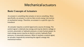
- 1. Mechanicalactuators Basic Concepts of Actuators An actuator is something that actuates or moves something. More specifically, an actuator is a device that coverts energy into motion or mechanical energy. Therefore, an actuator is a specific type of a transducer An actuator requires a control signal and a source of energy. The control signal is relatively low energy and may be electric voltage or current, pneumatic or hydraulic pressure, or even human power. Its main energy source may be an electric current, hydraulic fluid pressure, or pneumatic pressure. When it receives a control signal, an actuator responds by converting the signal's energy into mechanical motion.
- 2. Type of actuators: Hydraulic actuators Pneumatic actuators Electric actuators
- 3. thermal or magnetic Mechanical actuator
- 4. Example of actuators: • Comb drive. • Digital micro mirror device. • Electric motor. • Electroactive polymer. • Hydraulic cylinder. • Piezoelectric actuator. • Pneumatic actuator. • Screw jack. • Servomechanism. • Solenoid. • Stepper motor. • Shape-memory alloy. • Thermal bimorph. • Hydraulic actuators.
- 5. Hydraulic cylinder : ( linear hydraulic motor) Is a mechanical actuator that is used to give a unidirectional force through a unidirectional stroke. It has many applications, notably in construction equipment (engineering vehicles), manufacturing machinery, and civil engineering
- 6. 1. Pins & retainers 2. Ports 3. Piston nut 4. Piston 5. Piston nut 6. Piston 7. Piston seal 8. Tie – Rods 9. Cylinder shaft 10. Tube 11. Tube seal 12. Rod seal 13. Rod Cap & Clevis Cap 14. Rod Wiper 15. Threadad shaft (on ASAE cylinders ) 16. Rod Clevis
- 7. Basic parts: • Cylinder barrel The main function of the cylinder body is to hold cylinder pressure. The cylinder barrel is mostly made from a seamless tube. The cylinder barrel is ground and/or honed internally with a typical surface finish of 4 to 16 microinch,honing process and Skiving & Roller burnishing (SRB) process are the two main types of processes for manufacturing cylinder tube.[3] The piston reciprocates in the cylinder. • Cylinder base or cap The main function of the cap is to enclose the pressure chamber at one end. The cap is connected to the body by means of welding, threading, bolts, or tie rod. Caps also perform as cylinder mounting components [cap flange, cap trunnion, cap clevis]. Cap size is determined based on the bending stress. A static seal / o-ring is used in between cap and barrel (except welded construction).
- 8. • Cylinder head The main function of the head is to enclose the pressure chamber from the other end. The head contains an integrated rod sealing arrangement or the option to accept a seal gland. The head is connected to the body by means of threading, bolts, or tie rod. A static seal / o-ring is used in between head and barrel. • Piston The main function of the piston is to separate the pressure zones inside the barrel. The piston is machined with grooves to fit elastomeric or metal seals and bearing elements. These seals can be single acting or double acting. The difference in pressure between the two sides of the piston causes the cylinder to extend and retract. The piston is attached with the piston rod by means of threads, bolts, or nuts to transfer the linear motion.
- 9. • Piston rod The piston rod is typically a hard chrome-plated piece of cold-rolled steel which attaches to the piston and extends from the cylinder through the rod-end head. In Seal gland • Seals Attaches to the piston and extends from the cylinder through the rod-end head. In double rod-end cylinders, the actuator has a rod extending from both sides of the piston and out both ends of the barrel. The piston rod connects the hydraulic actuator to the machine component doing the work. This connection can be in the form of a machine thread or a mounting attachment. The piston rod is highly ground and polished so as to provide a reliable seal and prevent leakage.
- 10. Hydraulic cylinder Application for hydraulic actuators :
- 11. This circuit is designed as shown in Figure 10.2. When the four-way valve is in its spring-centered position, the cylinder is hydraulically locked. Also the pump is loaded back to the tank at atmospheric pressure. When the four-way valve is actuated into the flow path configuration of the left envelope, the cylinder is extended against its force load (Flood) as oil flows from port P through port A. The oil at the rod end of the cylinder is free to flow back into the reservoir through the four-way valve from port B through port T. The cylinder will not extend if the oil in the rod end is not allowed to flow back to the reservoir. When the four-way valve is de-activated, the spring-centered envelope prevails, and the cylinder is once again hydraulically locked. When the four-way valve is actuated in the right envelope configuration, the cylinder retracts, as oil flows from port P through port B. Oil in the blank end is allowed to flow back to the reservoir from port A through port T of the four-way valve. At the end of the stroke, there is no system demand for oil. Therefore the pump flow goes through the relief valve at its set pressure, unless the four-way valve is de-activated. In any event, the system is protected from cylinder overloads.
- 12. Thanks you