
Recommended
More Related Content
Similar to MICE I - Module 2 Notes.pptx
Similar to MICE I - Module 2 Notes.pptx (20)
More from SahalSachu
More from SahalSachu (12)
Recently uploaded
Recently uploaded (20)
MICE I - Module 2 Notes.pptx
- 1. Scavenging
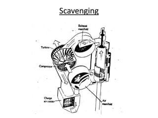
- 2. Scavenging • Scavenging is the process whereby air at a pressure greater than that of atmospheric pressure is used to push the exhaust gas out of the cylinder of an engine. • Unlike the 4 stroke engine, a two stroke diesel engine does not use the piston to push out the exhaust gas, instead, air enters the cylinder around bottom dead center and sweeps or scavenges the exhaust gas from the cylinder.
- 3. Scavenging
- 4. Scavenging • Removal of exhaust gas from the cylinder after combustion and its replenishment with air for subsequent combustion. • Efficient scavenging is necessary for good combustion • The passage of scavenge air will also assist cooling of piston and cylinder
- 5. Scavenging • Two-stroke engines rely upon a charge of scavenge air under slight pressure sweeping through the cylinder and expelling the exhaust gas in front of it • This process takes place while both scavenge and exhaust connections are open and the piston is near the bottom of the cylinder • Hence a very short period of time is available for scavenging to take place.
- 6. Scavenging • Air must be supplied at a higher pressure than that in the exhaust manifold using any of the below means: - Reciprocating scavenge pumps - Rotary blowers – electric or engine driven - Turbochargers Scavenge air enters through ports near the bottom of the cylinder liner when these are uncovered by the piston moving down to the BDC until the piston again covers the ports during its upward stroke. The directional flow of air within the cylinder is decided by the engine design and the exhaust arrangements.
- 7. Scavenging • A scavenging system must fulfill the following requirements: - The exhaust ports / valve must open earlier to provide a lead to the exhaust. During this period the pressure in the cylinder falls below the scavenge pressure. - The scavenge ports must be closed after the process of gas exchange is completed - Loss of fresh air charge escaping through the exhaust ports should be minimised
- 8. Scavenging
- 9. Scavenging A scavenging process may be considered to take place in a number of stages. 1. First period or the blow down period: - This period begins at the moment the exhaust ports are uncovered. - The exhaust gases are blown down in the exhaust manifold where a lower pressure exists - The gas is compressed at the vicinity of exhaust ports inside the cylinder leaving a rarefied area immediately behind it. The pressure drops below the scavenge air box pressure.
- 10. Scavenging 2. Second period or the scavenging period proper. - The period begins after the scavenge ports are opened. - Scavenge air enters the main cylinder, sweeps the residual combustion gases out of the cylinder and charges the cylinder with fresh air. - The mass of air drawn in the cylinder depends on the difference in pressure between scavenge trunk and exhaust system.
- 11. Scavenging 3. Third period - A further period in which an effort is made to contain the air taken in the cylinder already. The process of charging the cylinder is associated with a degree of inter-mixing with exhaust gases which affects the purity of charge and increases the charge temperature.
- 12. Scavenging There are two basic methods of scavenging: 1. Uniflow or through-scavenge - air passes straight up through the length of the cylinder forcing the exhaust through ports or valves at the top of the cylinder. 2. Reverse flow scavenging - in which air passes over the piston crown and rises to form a loop within the cylinder, expelling gas through exhaust ports. Depending on the relative positions of exhaust and air ports, the reversed flow system are divided into: 1. Full loop scavenging with exhaust on top of air ports at the same side of the engine 2. Cross scavenging with scavenge ports facing the exhaust ports
- 15. Scavenging
- 16. Uniflow Scavenging - Air flows in streams with slight induced rotational motion. - The charge is not allowed to change direction and hence intermixing is minimum. - Due to absence of eddies and turbulence it is easier to push the products of combustion without mixing and short circuiting. - Scavenge efficiency is the highest. - The system is particularly suitable in slow speed engines with long stroke and large area of escape for exhaust gases. - Uniflow scavenging is achieved by: 1. By two pistons working in one cylinder as in opposed piston engine 2. By a poppet valve which provides large area for escape of exhaust gases so that the desired pressure drop in the cylinder is achieved without turbulence at exhaust 3. By an exhaust piston controlling the exhaust ports, while the air inlet ports are controlled by the power piston.
- 17. Reversed flow Scavenging - The engines employing a reversed flow system of scavenging are structurally simpler. - Owing to the absence of cams, valves and valve gear, engines are simple and sturdy. - Cylinder head can better withstand the thermal stresses.
- 18. Reversed flow Scavenging The disadvantages with the system are: - The piston skirt has to be much longer than that for a uniflow scavenged engine. This is because the skirt has to seal the scavenge and exhaust ports when the piston is at TDC. - There is a greater possibility of intermixing air and exhaust. As a result the purity of charge is less and the charge temperature is higher - A sharp temperature difference exists within a small area around the scavenge and exhaust ports. Hence the possibility of thermal cracks at the bars and the chance of thermal distortion of the liner are greater. - The exhaust back pressure may rise due to narrowing of exhaust passage by deposit of unburnt carbon. - The piston rings will wear out unevenly
- 19. Cross Scavenging Disadvantages: - The scavenging air is not able to get rid of the layer of exhaust gas near the wall resulting in poor scavenging - Some of the fresh charge also goes directly into the exhaust port resulting in poor bmep.
- 20. Loop Scavenging - Loop scavenging avoids the short-circuiting of the cross scavenged engine and thus improves the scavenging efficiency.
- 21. Scavenging pumps Since the pumping action is not carried out by the piston of a two-stroke engine, a separate pumping mechanism, called the scavenging pump, is required to supply scavenging air to the cylinder. Types of scavenging pumps range from crankcase compression, piston type blowers to roots blower. Careful selection of scavenging pump is important since the design of a two-stroke engine is affected by the type of scavenging pump used.
- 22. Crankcase scavenging • Crankcase is used for compressing the incoming air and then transferring it to the cylinder through a transfer port. • Cheap in initial cost • Uneconomical and inefficient in operation • Amount of air which can be used for scavenging is less than the swept volume of the cylinder due to low volumetric efficiency of the crankcase which contains a large dead space. • Since the delivery ratio is less it is not possible to scavenge the cylinder completely of the products of combustion and some residual gases always remain in the cylinder resulting in low mep. • Also oil vapours from the crankcase mixes with the scavenging air resulting in high oil consumption.
- 24. Piston, Roots and Centrifugal Blowers • Piston type blowers are used only for low speed engines. • Roots blower is preferred for small and medium output engines • Centrifugal blower is preferred for large and high output engines
- 25. Piston, Roots and Centrifugal Blowers
- 26. Exhaust gas turbocharging system
- 27. Compression Ratio (CR) • Thermal efficiency of a Diesel engine increases with increase in CR. But a very high CR gives a very high peak pressure and temperature. The crankshaft and other components are to be designed to withstand the peak load. Hence too high CR would involve higher weight and cost of engine. • The upper limit of CR is therefore fixed by the strength of the cylinder, the bearings and other parts whose stresses are determined by peak mechanical and thermal loading.
- 28. Compression Ratio (CR) • Increase in CR in the lower range gives a proportionate gain in thermal efficiency. But in the higher range the gain becomes progressively less. • Higher CR helps easy starting from cold condition.
- 29. CR and Supercharging • Mep can be increased by burning more fuel, but this increases the fuel consumption and maximum pressure. • Maximum pressure rise is a major factor in the mechanical design of the engine. • Hence if it is desired not to increase the maximum pressure, a further boost of the mep is possible by reducing the CR with simultaneous increase in the charge air pressure at the intake. This principle is adopted in high pressure turbo-charged engines.
- 30. Supercharging • A supercharger is an air compressor that increases the pressure or density of air supplied to an internal combustion engine. This gives each intake cycle of the engine more oxygen, letting it burn more fuel and do more work, thus increasing power. • Power can be increased by increasing the compression ratio which increases the maximum cylinder pressure. But with super charging, the rate of increase in max pressure is less than the rate of increase of brake mean effective pressure. The rate of increase of max temperature is also low in case of supercharging. • Power for the supercharger can be provided mechanically by means of a belt, gear, shaft, or chain connected to the engine's crankshaft. When power is provided by a turbine powered by exhaust gas, a supercharger is known as a turbosupercharger – typically referred to simply as a turbocharger.
- 31. Supercharging • A naturally aspirated engine draws air of the same density as the ambient atmosphere. • Since this air density determines the maximum weight of fuel that can be effectively burned per working stroke in the cylinder, it also determines the maximum power that can be developed by the engine. • Increasing the density of the charge air by applying a suitable compressor between the air intake and the cylinder increases the weight of air induced per working stroke, thereby allowing a greater weight of fuel to be burned with a consequent rise in specific power output.
- 32. Supercharging • Supercharging is meant for increase in output by burning more fuel, it has no relation with thermal efficiency. However a slight gain in thermal efficiency results because of better combustion of fuel. • The power is a function of average pressure but the engine dimensions are ascertained on the basis of maximum pressure. Supercharging increases the average pressure without appreciable increasing the maximum pressure. • Thus it is a means of improving power without increasing the weight of the engine. Hence supercharging improves the power to weight ratio of the engine.
- 33. Supercharging • The mass of fuel required to be injected for generation of a larger power has to be more than that compared to a non-supercharged engine. • Supercharged engines must have a faster rate of heat release within almost the same period of injection for better thermal efficiency. Hence supercharging is associated with high maximum pressure also. • But the rate of increase in max pressure is much less than the rate of increase in power output.
- 34. Supercharging • The power expended in driving the compressor has an important influence on the operating efficiency of the engine. • It is relatively uneconomical to drive the compressor direct from the engine by chain or gear drive because some of the additional power is thereby absorbed and there is an increase in specific fuel consumption for the extra power obtained.
- 35. Supercharging • About 35 per cent of the total heat energy in the fuel is wasted to the exhaust gases, so by using the energy in these gases to drive the compressor an increase in power is obtained in proportion to the increase in the charge air density. • The turbocharger comprises a gas turbine driven by the engine exhaust gases mounted on the same spindle as a blower, with the power generated in the turbine equal to that required by the compressor.
- 36. Supercharging Advantages of exhaust gas turbo-blower system: • A substantial increase in engine power output for any stated size and piston speed, or conversely a substantial reduction in engine dimensions and weight for any stated horsepower. • An appreciable reduction in the specific fuel consumption rate at all engine loads. • Increased reliability and reduced maintenance costs
- 37. Pulse System • A certain mass of a gas at a higher pressure and temperature can be made to work by expanding to a lower pressure and temperature. • The temperature and pressure that prevails in a cylinder at the point of exhaust will be 500 to 600 deg C and 3.5 to 4 bar
- 38. Pulse System • The expansion that takes place in the diesel cylinder is limited. • Complete expansion of the gases from the ignition pressure to the atmospheric pressure cannot be achieved. • Pulse system aims at further expansion of gas beyond that had taken place in the engine cylinder. • The loss of work in the cylinder due to incomplete expansion appears as work in the turbine and thus input to the compressor shaft.
- 39. Pulse System • The first phase of exhausting is a blowdown process. • The exhaust ports act as nozzles which produce a high velocity stream of gas down to the exhaust pipe. The pipe constructed in small diameter, is quickly pressurised to form a pressure pulse. The pulsating pressure wave reaches up to the nozzle of the turbine where further expansion of the gas takes place.
- 40. Pulse System • When the turbine works in this manner by expanding the unutilised part of expansion taking place in the nozzles and blades of the turbine it is called pulse system of turbocharging.
- 41. Pulse System • The speed of the compressor changes according to the exhaust temperature and pressure and the demand of the engine. • It supplies air in a matching relationship automatically starting from part load to full load operation. It also responds well to quick load fluctuation. • It is necessary for a multi-cylinder engine to arrange the exhaust pipes in divided ducts up to the turbocharger. • The turbocharger may have gas inlet at two to four points, each point supplying one segment containing a number of nozzles.
- 42. Pulse System The design of exhaust ducting should meet the following requirements: - To preserve the kinetic energy of blowdown by interposing resistance in the line as the gas is taken through narrow, short and straight pipe lines up to the entry of the turbine - To prevent the interference in the scavenging of one by the exhausting of the other - To distribute energy of the exhaust gas equally amongst the number of turbochargers - To tune the exhaust system so that the manifold pressure pulsation is not reflected back to the engine
- 43. Pulse System Exhaust grouping: If the exhaust period of one cylinder overlaps with the scavenge of the other, the exhaust pressure from the cylinder which is exhausting interferes with the scavenging of the other cylinder. In order to avoid occurrence of such combinations in multi cylinder two or four stroke cycle engines, the cylinders are selectively grouped with connections to two or more exhaust pipes. The pipes are arranged in smaller diameters to preserve the pressure pulse due to blow down and in short straight lengths to prevent any loss of energy.
- 44. Pulse System Exhaust grouping: • A three-cylinder four stroke cycle engine will have the firing sequence separated by 2400. • Hence a four stroke supercharged engine having number of cylinders four and above will require exhaust grouping.
- 45. Exhaust Grouping
- 46. Pulse System • Makes full use of the higher pressure and temperature of the exhaust gas during the blow down period • While rapidly opening the exhaust valves, exhaust gas leave the cylinder at high velocity as pressure energy is converted into kinetic energy to create the pressure wave or pulse in exhaust • These pressure waves or pulses are lead directly to the turbocharger • Exhaust pipe, so constructed in small diameter, is quickly pressurized and boosted up to form pressure pulse or wave • Pressure waves reach the turbine nozzles and further expansion takes place.
- 47. Pulse System Turbocharger Arrangement in Pulse System: • Interference exists between exhausting and scavenging among cylinders • To prevent this, cylinders are grouped relatively with connections to two or more exhaust pipes • Pipes are arranged, in small diameter to boost up pressure pulse and in short, straight length to prevent energy loss • Number of exhaust branch depends upon firing order, number of cylinders and turbocharger design
- 48. Pulse System Advantages: • At low load and low speed it is more efficient (Still efficient when Bmep is < 8 bar) • No need of assistance with scavenge pump and blower at any load change. • It is highly responsive to change in engine condition giving good performance of all speed of engines. • High available energy at turbine • Good turbocharger acceleration
- 49. Pulse System Disadvantages: • The exhaust grouping is complicated. • Different sizes of exhaust pipes are needed for spare. • High pressure exhaust from one cylinder would pass back into another cylinder during the low pressure scavenging period thus adversely effecting the combustion efficiency.
- 50. Constant Pressure System • In this system the admission of gas to turbine blades is at constant velocity distributed uniformly over the entire blade area • All cylinders exhaust into a pipe of large diameter which is common to all cylinders. • The pressure pulses are first damped out by expanding the gas in this chamber which is then maintained at a constant pressure. • The exhaust manifold acts as a reservoir and supply the turbocharger at a steady pressure through one entry point.
- 51. Constant Pressure System • In the constant pressure system no attempt is made to recover work due to unutilised expansion in the cylinder. • The exhaust is allowed to throttle from the cylinder through the exhaust valve (or port) without doing any work into the exhaust manifold which is of larger diameter. • The work transfer takes place solely by virtue of enthalpy drop as the exhaust gases expand through the nozzles and over the blades of the turbine. • The turbine operation is more efficient.
- 52. Constant Pressure System • As the diesel cylinder is uprated, the mep is increased and the enthalpy content of the exhaust gas is considerably more. But the pulse system fails to boost up the turbine to supply the additional air now required. • As an improvement over pulse system, the constant pressure turbocharging has been developed and successfully employed.
- 53. Constant Pressure System • Exhaust gas from all cylinders into a common large manifold where pulse energy is largely dissipated. • The gas flow will steady rather than intermittent and at a constant pressure at turbine inlet. Turbocharger Arrangement in Constant Pressure System: • No exhaust grouping • Exhaust gases enter into large common manifold and then to turbine • Firing order not considered
- 54. Constant Pressure System Disadvantages: • For successful operation of constant pressure system, there must always be a higher pressure in the compressor outlet than the exhaust pipe after the cylinder. This condition is difficult to achieve at part load range of operation or during acceleration period, when the energy level in the exhaust gas through put to the turbine is low. • The resultant delay in turbo-blower acceleration, or deceleration, results in poor combustion during transition periods.
- 55. Constant Pressure System Advantages: - Better and more rational use of exhaust heat - A steady pressure before the turbine and hence an efficient turbine operation - The work transfer at the turbine wheel is smooth - The compressor capacity can be increased as more energy is available for utilisation according to power - Since pressure pulses are not required, expansion in the cylinder can be carried longer in the stroke to a lower temperature and pressure, thus attaining a gain in output.
- 56. Constant Pressure System Advantages: - A reduction in specific fuel consumption due to better scavenging - Since exhaust grouping is not necessary, the exhaust piping is made simpler. - The lack of restriction on exhaust pipe length permits greater flexibility in positioning the turbo-blower relative to the engine. - Typical positions are at either or both ends of the engine, at one side above the air manifold or on a flat adjacent to the engine.
- 57. Turbocharging in Four stroke engine • Exhaust gas turbocharged single-acting four- stroke marine engines can deliver three times or more power than naturally aspirated engines of the same speed and dimensions. • At one time almost all four-stroke engines operated on the pulse system, though constant pressure turbocharging has since become more common as it provides greater fuel economy while considerably simplifying the arrangement of exhaust piping.
- 58. Turbocharging in Four stroke engine • In matching the turboblower to the engine, a free air quantity in excess of the swept volume is required to allow for the increased density of the charge air and to provide sufficient air for through-scavenging of the cylinders after combustion. • Modern engines carry bmeps up to 28 bar in some cases, requiring greater proportions of excess air which is made possible by the latest design of turbocharger with pressure ratios as high as 5:1.
- 59. Turbocharging in Four stroke engine • Optimum values of power output and specific fuel consumption can be achieved only by utilization of the high energy engine exhaust pulses. • The engine exhaust system should be so designed that it is impossible for gases from one cylinder to contaminate the charge air in another cylinder, either by blowing back through the exhaust valve or by interfering with the discharge of gases from the cylinder. • During the period of valve overlap it follows that the exhaust pressure must be less than air charging pressure to ensure effective scavenging of the cylinder to remove residual gases and cooling purposes.
- 60. Turbocharging in Two stroke engine • Compared with four-stroke engines, the application of pressure charging to two-stroke engines is more complicated because, until a certain level of speed and power is reached, the turbo-blower is not self-supporting. • At low engine loads there is insufficient energy in the exhaust gases to drive the turbo-blower at the speed required for the necessary air-mass flow. • In addition, the small piston movement during the through scavenge period does nothing to assist the flow of air, as in the four-stroke engine.
- 61. Turbocharging in Two stroke engine • Accordingly, starting is made very difficult and off-load running can be very inefficient; below certain loads it may even be impossible. • A solution was found by having mechanical scavenge pumps driven from the engine arranged to operate in series with the turbo- blowers. • Standard on modern engines, however, are electrically driven auxiliary blowers.
- 62. Supercharging of SI engines • Supercharging increases the tendency to knock and pre-ignite. • As the flame front propagates from spark plug towards BDC , the flame front exerts pressure on the end gases at bottom and this pressure if sustains for time equal to the ignition lag of end gases and temperature rises above self-ignition temp of fuel, then end gases would ignite before the flame reaches there and another flame front propagates in the direction towards TDC and when it will collide with original flame front, shock wave will generate which leads to enormous pressure rise .
- 63. Supercharging of SI engines • This means a reduction in the ignition delay is a favorable condition for knocking. • Supercharging will cause increased intake pressure and temperature which will reduce the ignition delay, thus increasing the tendency to knock.
- 64. Supercharging of SI engines • Hence the supercharged SI engines employ lower compression ratios. • This along with increased heat losses result in lower thermal efficiency. • Thus supercharged SI engines have a greater fuel consumption than naturally aspirated engines. • Injection of water into the combustion chamber and intercooling of charge air before feeding to the engine are the methods used to overcome the issues.
- 65. Supercharging of SI engines • Because of poor fuel economy supercharging is used only when a large amount of power is needed or when more power is needed to compensate altitude loss.
- 66. Supercharging in CI engines • Detonation occurs because of increased ignition delay - if ignition delay is more then more fuel will accumulate till ignition starts hence ignition of more fuel instantaneously leads to pressure rise called detonation. • Supercharging will cause increased intake pressure and temperature which will reduce the ignition delay thus reducing the tendency for detonation.
- 67. Supercharging in CI engines • The increase in pressure and temperature of intake air reduces ignition delay and hence the rate of pressure rise during combustion, resulting in better and smoother combustion. This allows a poor quality fuel to be used. • The increase in intake air temperature reduces volumetric and thermal efficiency but the increase in density compensates for this.
- 68. Charge air cooling • The increased weight or density of air introduced into the cylinder by pressure charging enables a greater weight of fuel to be burned, and this in turn brings about an increase in power output. • The increase in air density is fractionally offset by the increase of air temperature resulting from adiabatic compression in the turbo- blower, the amount of which is dependent on compressor efficiency.
- 69. Charge air cooling • For a charge air pressure of, say, 0.35 bar, the temperature rise is of the order of 330C— equivalent to a 10% reduction in charge air density. • For a charge air pressure of 0.7 bar, the temperature rise is some 600C, which is equivalent to a reduction of 17% in the charge air density. • Much of this potential loss can be recovered by the use of charge air coolers.
- 70. Charge air cooling Charge air cooling has a double effect on engine performance - • By increasing the charge air density it thereby increases the weight of air flowing into the cylinders, and by lowering the air temperature it reduces the exhaust temperature and the engine thermal loading. The increased power is obtained without loss, and with an improvement in fuel economy. It is important that charge air coolers should be designed for low pressure drop on the air side; otherwise, to obtain the required air pressure the turbo-blower speed must be increased.
- 71. Charge air cooling • A typical construction has cooling surface that consists of two banks of rolled-in aluminium- brass finned tubes which are expanded in tube plates. • The top tube plate is firmly held while the bottom plate can slide to take up expansion of tubes. • Air is passed over the fins and cooled down. • Cooling water passes through the tubes in two straight passes.
- 73. Charge air cooling • The air must not be cooled below the dew point of the vapour at the condition of pressure, temperature and humidity existing in the charge air pipe, since this will cause condensation.
- 74. Turbocharger
- 76. Radial flow turbocharger • The diesel engine exhaust gases enter through the water- cooled gas inlet casing (50), expand in the nozzle ring (30) and supply energy to the shaft (20) by flowing through the blading (21). • The gases exhaust to the open air through the gas outlet casing (60), which is also water cooled, and the exhaust piping. • The charge air enters the compressor through an inlet stub (82) and the silencer filter (80). • It is then compressed in the inducer and the impeller (25), flows through the diffuser (28) and is fed to the cooler via the pressure stubs on the compressor casing (74).
- 77. Radial flow turbocharger • Air and gas spaces are separated by the heat insulating bulkhead (70). • In order to prevent exhaust gases from flowing into the balance channel (Z) and the turbine side reservoir, barrier air is fed from the compressor to the turbine rotor labyrinth seal via channel X.
- 78. Radial flow turbocharger • The rotor (20) has easily accessible bearings (32, 38) at both ends, which are supported in the casing with vibration damping spring elements. • Either roller or plain bearings are used but for the most common construction using roller bearings a closed loop lubrication system with an oil pump directly driven from the rotor is used (47, 48). • The bearing covers are each fitted with an oil filter, an oil drain opening and an oil gauge glass. • On models with plain bearings, where the quantity of oil required is large, these are fed from the main engine lubricating oil system.
- 80. Turbocharger
- 81. Radial flow turbocharger • A turbocharger consists of two sections: - Compressor - Turbine
- 82. Compressor A centrifugal compressor which has a large capacity to handle air and is simple in construction is the best choice where a high mass flow with low delivery pressure is demanded. It consists of a rotor or impeller containing radial vanes mounted on a shaft and enclosed in a casing with fine clearances.
- 83. Compressor • A single-stage centrifugal compressor will have the following divisions: - an intake system - the impeller channel - a diffusion system
- 84. Intake system • The intake system consists of an intake silencer, guide-ways and impeller intake guide vanes or inducers. • The function of the system is to admit air to the hub of the impeller without shock and friction.
- 85. Impeller channel • The impeller channel begins from the center of the hub and extends radially outwards to the tip. • Air is given a centrifugal force so that it leaves the impeller vane at a high velocity. • The displacement of air creates a suction inducting more air through the inducer.
- 86. Impeller channel • The impeller is usually made by forging of light alloy of aluminium-silicon. • The physical properties of such material are lightness, strength together with toughness, and its capacity for a smooth surface finish.
- 87. Diffusion system • Comprises of a stationary vaned diffuser and a vaneless space of gradually increasing area. • Diffuser is the name given to the fixed vanes surrounding the impeller. • The high velocity of air leaving the impeller tip enters the fixed diverging vanes of the diffuser. • The air stream is slowed down in the diffusion process where some of the kinetic energy is converted to a pressure head. • By the diffusion process the air is slowed down to intake velocity with a rise in pressure. • The process involves compression and consequently a rise in temperature.
- 89. Turbine • The turbine is driven by the engine exhaust gas, which enters via the gas inlet casing. • The gas expands through a nozzle ring where the pressure energy of the gas is converted to kinetic energy. • This high velocity gas is directed onto the turbine blades where it drives the turbine wheel, and thus the compressor at high speeds (10 -15000 rpm). • The exhaust gas then passes through the outlet casing to the exhaust uptakes.
- 90. Turbine • The nozzle ring is where the energy in the exhaust gas is converted into kinetic energy. • It is fabricated from a creep resistant chromium nickel alloy, heat resisting moly-chrome nickel steel or a nimonic alloy which will withstand the high temperatures and be resistant to corrosion. • Nimonic alloys typically consist of more than 50% nickel and 20% chromium with additives such as titanium and aluminium.
- 91. Turbine • Turbine blades are usually a nickel chrome alloy or a nimonic material (a nickel alloy containing chrome, titanium, aluminium, molybdenum and tungsten) which has good resistance to creep, fatigue and corrosion. • Blade roots are of fir tree shape which give positive fixing and minimum stress concentration at the conjunction of root and blade. • The root is usually a slack fit to allow for differential expansion of the rotor and blade and to assist damping vibration. • On small turbochargers and the latest designs of modern turbochargers the blades are a tight fit in the wheel.
- 92. Turbine
- 93. Turbine • Lacing wire is used to dampen vibration, which can be a problem. • The wire passes through holes in the blades and damps the vibration due to friction between the wire and blade. • It is not fixed to each individual blade. • The wire can pass through all the blades, crimped between individual blades to keep it located, or it can be fitted in shorter sections, fixed at one end, joining groups of about six blades.
- 94. Turbine • A problem with lacing wire is that it can be damaged by foreign matter, it can be subjected to corrosion, and can accelerate fouling by products of combustion when burning residual fuels. • Failure of blading due to cracks emanating from lacing wire holes can also be a problem. • All the above can cause imbalance of the rotor.
- 95. Turbine
- 96. Turbine • The turbine casing is of cast iron. • Some casings are water cooled which complicates the casting. • Water cooled casings are necessary for turbochargers with ball and roller bearings with their own integral LO supply (to keep the LO cool). • Modern turbochargers with externally lubricated journal bearings have uncooled casings. • This leads to greater overall efficiency as less heat energy is rejected to cooling water and is available for the exhaust gas boiler.
- 97. Turbine • Labyrinth seals or glands are fitted to the shaft and casing to prevent the leakage of exhaust gas into the turbine end bearing. • To assist in the sealing effect, air from the compressor volute casing is led into a space within the gland. • A vent to atmosphere at the end of the labyrinth gives a guide to the efficiency of the turbine end gland. • Discoloring of the oil on a rotor fitted with a roller bearing will also indicate a failure in the turbine end gland.
- 98. Turbine • A labyrinth arrangement is also fitted to the back of the compressor impeller to restrict the leakage of air to the gas side.
- 100. Turbocharger • The horizontal rotor is constructed in parts and made hollow out of high alloy nickel chromium steel. • The shaft carries a single stage axial gas turbine wheel at one end and a radial single stage compressor at the other end. • The shaft rests on sleeve bearings. • At the compressor end there is a thrust bearing for keeping the rotor assembly in its true axial alignment while it is free to expand at the other end. • The rotor shaft is provided with shrunk on bushes for bearings and shrunk on labyrinth seal. • The labyrinth seals are supplied with sealing air taken from the scroll housing through outside tubes, which are easy to inspect and clean.
- 101. Turbocharger • The casing is divided to form the turbine and the compressor housings at two ends. • The subdivision wall is provided with water cooling arrangement. • The air is admitted axially through the impeller and passes radially outwards to the tips. • The blower side is equipped with a silencer.
- 102. Turbocharger • The turbine end housing contains one or two gas inlets. A grid is provided before the inlet to arrest any large piece of metal from entering the turbine and causing damage to the blades. • The turbine bearings are lubricated from an overhead tank with a constant static pressure head above the bearings. • This ensures the lubrication is continued unaffected in the event of lubricating oil pump failure. • The overflow sight glass provides means for inspection of the oil quantity and flow at all times.
- 103. Compressor Characteristics • The relationship between speed of rotation, mass flow and pressure ratio is termed as compressor characteristics.
- 104. Compressor Characteristics • A typical characteristic curve for one particular speed is shown here.
- 105. Compressor Characteristics • At point C the valve is fully open, hence no obstruction for the flow to move ahead. • The static pressure developed is negligible but the velocity is maximum and the shaft power is high. • As the resistance to flow is increased the mass flow is reduced causing the pressure to rise. • A characteristic curve is obtained when the pressure ratio is plotted for each position of valve opening.
- 106. Compressor Characteristics • The pressure ratio attains a maximum value at B. • If the flow is still reduced the pressure suddenly drops below the delivery pressure initiating surging or pumping of air back to the compressor. • Surging is defined as excessive aerodynamic pulsation in the air stream. • When the pressure ratio drops the air will flow back or surge to the compressor due to higher pressure downstream. • The next moment the compressor regains its pressure ratio and delivers.
- 107. Compressor Characteristics • Due to this characteristic of compressor at low mass flow rate, it cannot be worked at point left of maximum pressure ratio. • A compressor is most efficient within a narrow range on the right of the operating point B. • At every speed the compressor will have a different characteristic curve. • A family of such curves will show the characteristic of the compressor over a certain operating speed range.
- 108. Compressor Characteristics • That portion of the curve which remains on the left of the maximum pressure line is inoperable due to surge. • The line A joining these points is called the surge limit.
- 109. Blower Surging • Too low an air-mass flow at a given speed, or pressure ratio, will cause the blower to surge, while too high a mass flow causes the blower to choke, resulting in loss of pressure ratio and efficiency at a given speed. • The blower impeller, as it rotates, accelerates the air flow through the impeller, and the air leaves the blower with a velocity that is convertible into a pressure at the diffuser. • If, for any reason, the rate of air flow decreases, then its velocity at the blower discharge will also decrease; thus there will come a time when the air pressure that has been generated in the turbo-blower will fall below the delivery pressure. • There will then occur a sudden breakdown of air delivery, followed immediately by a backward wave of air through the blower which will continue until the delivery resistance has decreased sufficiently for air discharge to be resumed. • ‘Surging’ is the periodic breakdown of air delivery.
- 110. Blower surging • In the lower speed ranges surging is manifested variously as humming, snorting and howling. • If its incidence is limited to spells of short duration it may be harmless and bearable. In the higher speed ranges, however, prolonged surging may cause damage to the blower, as well as being most annoying to engine room personnel.
- 111. Problems associated with T/C Turbine blading: - Vibration of blades due to unbalance of the rotor as a result of deposits or fouling. - Vibration of blades due to the pulsating flow of exhaust gases admitted partially. - Fatigue failure may occur at the blade root. - Deposits on the blade surface
- 112. Problems associated with T/C Nozzle Ring: - Deposits from engine exhaust may clog the nozzles partially - Nozzles of small turbochargers with four stroke engines are narrow. Further narrowing will affect the performance causing high back pressure, loss of power, increase in thermal loading and frequent turbocharger surging.
- 113. Problems associated with T/C Bearings: - Erosion of the bearing balls or rollers caused by impurities present in lubricating oil may reduce their service life. - Heavy momentary loading due to vibration, bearing running dry or by contaminated oil, overheating, etc can also cause damage to the bearings.
- 114. Problems associated with T/C Turbine casing: - Thinning of the wall due to corrosion on the exhaust side - Loss of metal due to erosion by particles of impurities in the gas - Thermal cracks due to rapid load changes or due to cooling system failure - Thinning of wall due to corrosion in the cooling water space
- 115. Maintenance on turbocharger • Regular checking of oil level in the bearing sump • Changing of oil every 500 to 1000 running hours • Cleaning of air filter every 1000 running hours • Water washing of the turbine side every 48 running hours (A/Es) / leaving a port (M/E) • Dry / grit cleaning of the turbine side daily • Water washing of blower side every 24 / 48 running hrs • Renewal of bearings • Cleaning of cooling water chamber
- 116. Water washing of the turbine side • Accumulation of dirt on turbine will cause imbalance and lead to higher stresses of the bearings. • The water must be injected into the exhaust system ahead of the protecting grids with the engine running at low power. • The amount of water to be used depends upon the volume of gas and its temperature. • The flow rate must be so that 50% to 70% of the water is evaporated and escapes through the exhaust, while the remaining water is drained through the tap in the exhaust casing.
- 117. Water washing of the turbine side • The cleaning effect is based on the water solubility of the deposits, as well as on the mechanical effect of the striking water droplets.
- 118. Water washing of the turbine side
- 119. Water washing of the turbine side Cleaning procedure: - Reduce power until the turbocharger runs at the speed recommended by the maker - The temperature of the gas entering the turbine must be less than 300deg C - Open drain valve and ensure it is clear - Supply water at the recommended pressure and flow rate - Check water draining through the drain. Cleaning can be stopped when the water becomes clear. - Continue running for 3 more minutes to ensure all parts are dry