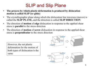
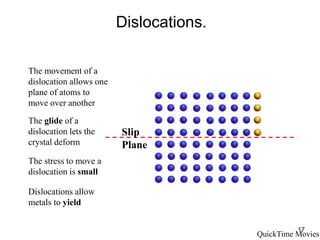
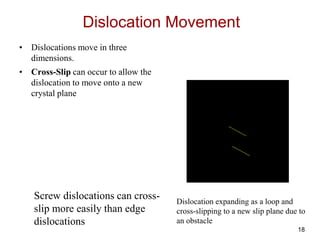
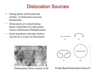
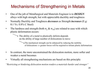
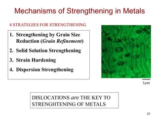
1
ISSUES TO ADDRESS...
• Why are dislocations observed primarily in metals
and alloys?
• How are strength and dislocation motion related?
• How do we increase strength?
• How can heating change strength and other properties?
CHAPTER 7: DISLOCATIONS AND
STRENGTHENING MECHANISMS
2
PART I: DISLOCATIONS
Introduction
• Two kinds of deformation are possible in materials:
1. ELASTIC or recoverable deformation
2. PLASTIC or permanent deformation
• On an atomic scale, plastic deformation corresponds to the net
movement of large numbers of atoms in response to an applied
stress
• During this process, inter-atomic bonds must be ruptured and
then reformed
• PLASTIC DEOFMRATION IN CRYTSLINE SOLIDS
INVOLVES MOTION OF DISLOCATIONS
• In metals motion of dislocations is easier than in ceramics
If dislocations don't move,
plastic deformation doesn't happen!
3
History of Dislocation Theory
• Theoretical strength of perfect crystals is much larger
than the experimentally measured
• In 1930’s it was hypothesized that this discrepancy
can be explained by linear crystalline defect called
dislocations
• It was 1950’s that the existence of such dislocations
defects was established by direct observation with the
electron microscopy
• Theory of dislocations explains many physical and
mechanical phenomena in metals
4
• Produces plastic deformation,
• Depends on incrementally breaking
and reforming of bonds
• Before and after the movement of dislocation
the atomic arrangement is perfect; only during
the passing of extra half plane the lattice
structure is disturbed
Plastically
stretched
zinc
single
crystal.
Dislocations and Plastic Deformation
5
SLIP and Slip Plane
• The process by which plastic deformation is produced by dislocation
motion is called SLIP (or glide)
• The crystallographic plane along which the dislocation line traverses (moves) is
called the SLIP PLANE, and the direction is called SLIP DIRECTION
• The direction of motion of edge dislocation in response to the applied shear
stress is parallel to the stress direction
• The direction of motion of screw dislocation in response to the applied shear
stress is perpendicular to the stress direction
However, the net plastic
deformation for the motion of
both types of dislocation is the
same
6
* HCP Metals are brittle due to few active slip systems
7
REVIEW:
Yielding of Metals by Dislocation Motion
Deformation occurs by yielding.
Deformation occurs in crystal slip bands
Cold-worked Brass
Slip Band
8
Yielding of Metals
Cold-worked Brass
Slip Plane
Yield occurs by movement of atoms
along crystal slip planes
9
Yielding of Metals
• Yielding (plastic deformation) occurs by the gliding of crystal
planes over each other.
10
Yielding of Metals
• Slip demonstrated in cadmium (HCP Crystal Structure)
11
Yielding of Metals
• Glide occurs on the closest packed
planes in the closest packed
directions
• These define Slip Systems:
Slip Plane + Slip Direction
QuickTime Movie
Hexagonally Close Packed
Plane and Directions
Three dimensional shape
change requires glide on
several slip systems
12
Yielding of Metals
• Some crystal structures have more
slip systems than others (FCC Vs.
HCP)
• Some slip systems glide more
easily than others (FCC Vs. BCC)
BCC
FCC
HCP
13
Yielding of Metals.
Slip Plane
The measured strength is
much lower than
the theoretical strength
Material Theoretical
Strength
(MPa)
Copper 20000
Iron 34000
Measured
Strength
(MPa)
0.5
28
The theoretical strength can be
calculated from the number of all atomic
bonds that must be broken at the same
time
There must another, easier
mechanism for slip
14
Slugs and Caterpillars
A slug sticks very well to all surfaces,
but glides very easily
15
Slugs and Caterpillars
Slug and Caterpillars glide by
creating dislocations.
16
Dislocations.
Dislocations in metal glide in
response to stress
High Voltage Transmission
Electron Microscopy of
dislocations moving in an Al-Si
alloy
The crystal planes glide in
metals by a similar mechanism
to the movement of the slug
17
Dislocations.
The movement of a
dislocation allows one
plane of atoms to
move over another
The glide of a
dislocation lets the
crystal deform
The stress to move a
dislocation is small
Dislocations allow
metals to yield
Slip
Plane
QuickTime Movies
18
Dislocation Movement
• Dislocations move in three
dimensions.
• Cross-Slip can occur to allow the
dislocation to move onto a new
crystal plane
Screw dislocations can cross-
slip more easily than edge
dislocations
Dislocation expanding as a loop and
cross-slipping to a new slip plane due to
an obstacle
19
Dislocation Sources
• During plastic deformation the
number of dislocation increases
dramatically
• Dislocations are created during
plastic deformation by dislocation
sources (Dislocation Multiplication)
• Grain boundaries and other defects
can also be a source of dislocations
Dislocations from a source in Si Frank-Read Dislocation Source
20
Mechanisms of Strengthening in Metals
• One of the job of Metallurgical and Materials Engineer is to DESIGN
alloys with high strength, but with appreciable ductility and toughness
• Normally Ductility and Toughness decreases as Strength increases (E.g:
0.1 Vs. 0.8% C Steel)
• The hardness and strength (both y & TS) are related to ease with which
plastic deformation occurs:
• In contrast, the more unconstrained the dislocation motion, more softer and
weaker a metal becomes
• Virtually all strengthening mechanisms are based on this principle:
The ability of a metal to plastically deform depends
on the ability of large number of dislocations to move
The mechanical strength can be enhanced by reducing the mobility
of dislocations  greater forces will be required to initiate plastic deformations
“Restricting or hindering dislocation motion renders a materials harder and stronger”
21
Mechanisms of Strengthening in Metals
1. Strengthening by Grain Size
Reduction (Grain Refinement)
2. Solid Solution Strengthening
3. Strain Hardening
4. Dispersion Strengthening
DISLOCATIONS are THE KEY TO
STRENGHTENING OF METALS
1µm
4 STRATEGIES FOR STRENGTHENING
22
1. Strengthening by Grain Size Reduction
• The size of grains, or the average grain diameter, in a polycrystalline
metal influences the mechanical properties
• Adjacent grains normally have different crystallographic orientations
• The Grain Boundaries act as BARRIER to Dislocation Motion
To continue plastic deformation across a grain boundary
slip or dislocation motion must take place across a grain boundary
Since the two grains have different orientations (Slip Plane and Directions)
it is difficult or impossible for dislocation to move across grains
The atomic disorder at grain boundary region will result in discontinuity of slip
planes from one grain into the other
23
• A fine-grained material (one that has small grains) is harder and stronger
than one that is coarse-grained, since the former has a greater total grain
boundary area to impede dislocation motion
• For many materials, the yield strength y, varies with grain size according
to the following equation termed as Hall-Petch Equation
• Where d is the average grain diameter and o and ky are constants for a
particular material
• Several techniques are available to control (decrease or increase) the grain
size
• Barrier "strength" increases with crystallographic mis-orientation across
the grain, i.e, Grain Boundary Angle
• Small-angle grain boundaries are not effective in interfering with the slip
process because of only slight misalignment across the boundary
• Boundaries between two different PHASES also provide barrier for
dislocation motion
yield  o kyd1/2
24
2. Solid-Solution Strengthening
• Another technique to strengthen and harden metals is alloying with
impurity atoms that go into either substitutional or interstitial site to
form a solid solution  Solid-Solution Strengthening
• Alloys are almost always stronger than pure metals
• Impurity atoms impose lattice strains on the surrounding host atoms
 Lattice strain field interactions between dislocations and these
impurity atoms results  Consequently dislocation movement is
restricted
• Impurity atoms smaller than host atoms exert a tensile strains on
the surrounding crystal lattice, and impurity atom larger than host
atoms exert a compressive strain on the surrounding crystal lattice
• These lattice strains interact with the compressive and tensile
stresses produced above and below the dislocation line (as already
discussed)
25
Distortions in the Lattice
Substitutional Atoms Vacancy
Defects in the crystal lattice
cause local distortions
Dislocation
26
Distortions in the Lattice
• Dislocations distort the crystal
lattice structure around the
dislocation core
• As the dislocation glides, its strain
field moves with it and interacts
with the strain fields of other
defects
• Resistance to slip is greater when
impurity atoms are present
• Thus a greater applied stress is
necessary to first initiate and then
continue plastic deformation for
solid-solution alloys as opposed to
pure metals
The lattice strain around
an edge dislocation
27
• Tensile strength & yield strength increase with wt% Ni
(i.e. increasing the concentration of impurity atoms)
• Empirical relation:
• Alloying increases y and TS
y ~ C1/2
Solid Solution Strengthening
in Copper: An Example
• Strength increases up to the Solubility Limit
28
3. Strain Hardening, Work Hardening, and
Cold Working
• Strain or work hardening is the phenomena whereby a ductile
metal becomes harder and stronger as it is plastically deformed
• It is also called cold working, because the temperature at which
deformation takes place is “cold” relative to the absolute melting
temperature of the metal (mostly metal strain harden at room
temperature)
Reason of Strain hardening:
• The number of dislocations increases with the amount of plastic
deformation
• Dislocations interact with each other to impede dislocation glide
Strain Hardening exponent ‘n’ in the Flow Curve Equation (t=Kt
n) is a
measure of the materials ability to strain harden; the largest its magnitude, the
greater the strain hardening ability for a given amount of plastic strain
29
• Cold Working  Room temperature deformation
• Common forming operations change the cross sectional area:
%CW 
Ao Ad
Ao
x100
Ao Ad
force
die
blank
force
-Forging -Rolling
-Extrusion
-Drawing
tensile
force
Ao
Ad
die
die
Cold Working (contd.)
The degree of plastic deformation is
commonly expressed as percent cold
work (%CW) instead of strain
30
Example: Steel, Brass and Copper
Yield and Tensile Strength Increases with Cold Work
31
As Expected the Ductility Decreases with Cold Work
32
Dislocation Based Explanation of the Strain Hardening
Phenomena
• The strain hardening phenomena is explained on the basis of
the dislocation-dislocation strain field interactions
• The dislocation density in a metal increases with plastic
deformation or cold work (due to dislocation multiplication or
the formation of new dislocations)  The average distance
between dislocations decreases
• Dislocation-dislocation strain interactions are mostly repulsive
• As the dislocation density increases the resistance to
dislocation motion by other dislocation becomes more
pronounced
• Thus, stress required to produce plastic deformation increases
with increasing cold work
• Strain hardening is often commercially used to enhance
(increase) the mechanical properties of metals
33
• Ti alloy after cold working:
• Dislocations entangle
with one another
during cold work.
• Dislocation motion
becomes more difficult.
Adapted from Fig.
4.6, Callister 6e.
(Fig. 4.6 is courtesy
of M.R. Plichta,
Michigan
Technological
University.)
DISLOCATIONS DURING COLD WORK
34
RECOVERY, RECRYSTALLIZATION,
and GRAIN GROWTH
• As discussed earlier plastically deforming a polycrystalline
metal specimen at low temperatures (COLD WORKING)
produces the following micro-structural and property changes:
– Change in grain shape
– Strain hardening
– An increase in dislocation density
• The microstructure and properties can be resorted back to the
PRE-COLD WORKED states by heat treatment at elevated
temperatures called ANNEALING
• Annealing normally consists of three steps:
– Recovery
– Recrystallization
– Grain Growth
35
Recrystallization is normally followed by grain growth
36
• Dislocations are observed primarily in metals
and alloys.
• Here, strength is increased by making dislocation
motion difficult.
• Particular ways to increase strength are to:
--decrease grain size
--solid solution strengthening
--cold work
--precipitate strengthening
• Heating (annealing) can reduce dislocation density
and increase grain size.
SUMMARY

Metallurgy (Dislocations)

  • 1.
    1 ISSUES TO ADDRESS... •Why are dislocations observed primarily in metals and alloys? • How are strength and dislocation motion related? • How do we increase strength? • How can heating change strength and other properties? CHAPTER 7: DISLOCATIONS AND STRENGTHENING MECHANISMS
  • 2.
    2 PART I: DISLOCATIONS Introduction •Two kinds of deformation are possible in materials: 1. ELASTIC or recoverable deformation 2. PLASTIC or permanent deformation • On an atomic scale, plastic deformation corresponds to the net movement of large numbers of atoms in response to an applied stress • During this process, inter-atomic bonds must be ruptured and then reformed • PLASTIC DEOFMRATION IN CRYTSLINE SOLIDS INVOLVES MOTION OF DISLOCATIONS • In metals motion of dislocations is easier than in ceramics If dislocations don't move, plastic deformation doesn't happen!
  • 3.
    3 History of DislocationTheory • Theoretical strength of perfect crystals is much larger than the experimentally measured • In 1930’s it was hypothesized that this discrepancy can be explained by linear crystalline defect called dislocations • It was 1950’s that the existence of such dislocations defects was established by direct observation with the electron microscopy • Theory of dislocations explains many physical and mechanical phenomena in metals
  • 4.
    4 • Produces plasticdeformation, • Depends on incrementally breaking and reforming of bonds • Before and after the movement of dislocation the atomic arrangement is perfect; only during the passing of extra half plane the lattice structure is disturbed Plastically stretched zinc single crystal. Dislocations and Plastic Deformation
  • 5.
    5 SLIP and SlipPlane • The process by which plastic deformation is produced by dislocation motion is called SLIP (or glide) • The crystallographic plane along which the dislocation line traverses (moves) is called the SLIP PLANE, and the direction is called SLIP DIRECTION • The direction of motion of edge dislocation in response to the applied shear stress is parallel to the stress direction • The direction of motion of screw dislocation in response to the applied shear stress is perpendicular to the stress direction However, the net plastic deformation for the motion of both types of dislocation is the same
  • 6.
    6 * HCP Metalsare brittle due to few active slip systems
  • 7.
    7 REVIEW: Yielding of Metalsby Dislocation Motion Deformation occurs by yielding. Deformation occurs in crystal slip bands Cold-worked Brass Slip Band
  • 8.
    8 Yielding of Metals Cold-workedBrass Slip Plane Yield occurs by movement of atoms along crystal slip planes
  • 9.
    9 Yielding of Metals •Yielding (plastic deformation) occurs by the gliding of crystal planes over each other.
  • 10.
    10 Yielding of Metals •Slip demonstrated in cadmium (HCP Crystal Structure)
  • 11.
    11 Yielding of Metals •Glide occurs on the closest packed planes in the closest packed directions • These define Slip Systems: Slip Plane + Slip Direction QuickTime Movie Hexagonally Close Packed Plane and Directions Three dimensional shape change requires glide on several slip systems
  • 12.
    12 Yielding of Metals •Some crystal structures have more slip systems than others (FCC Vs. HCP) • Some slip systems glide more easily than others (FCC Vs. BCC) BCC FCC HCP
  • 13.
    13 Yielding of Metals. SlipPlane The measured strength is much lower than the theoretical strength Material Theoretical Strength (MPa) Copper 20000 Iron 34000 Measured Strength (MPa) 0.5 28 The theoretical strength can be calculated from the number of all atomic bonds that must be broken at the same time There must another, easier mechanism for slip
  • 14.
    14 Slugs and Caterpillars Aslug sticks very well to all surfaces, but glides very easily
  • 15.
    15 Slugs and Caterpillars Slugand Caterpillars glide by creating dislocations.
  • 16.
    16 Dislocations. Dislocations in metalglide in response to stress High Voltage Transmission Electron Microscopy of dislocations moving in an Al-Si alloy The crystal planes glide in metals by a similar mechanism to the movement of the slug
  • 17.
    17 Dislocations. The movement ofa dislocation allows one plane of atoms to move over another The glide of a dislocation lets the crystal deform The stress to move a dislocation is small Dislocations allow metals to yield Slip Plane QuickTime Movies
  • 18.
    18 Dislocation Movement • Dislocationsmove in three dimensions. • Cross-Slip can occur to allow the dislocation to move onto a new crystal plane Screw dislocations can cross- slip more easily than edge dislocations Dislocation expanding as a loop and cross-slipping to a new slip plane due to an obstacle
  • 19.
    19 Dislocation Sources • Duringplastic deformation the number of dislocation increases dramatically • Dislocations are created during plastic deformation by dislocation sources (Dislocation Multiplication) • Grain boundaries and other defects can also be a source of dislocations Dislocations from a source in Si Frank-Read Dislocation Source
  • 20.
    20 Mechanisms of Strengtheningin Metals • One of the job of Metallurgical and Materials Engineer is to DESIGN alloys with high strength, but with appreciable ductility and toughness • Normally Ductility and Toughness decreases as Strength increases (E.g: 0.1 Vs. 0.8% C Steel) • The hardness and strength (both y & TS) are related to ease with which plastic deformation occurs: • In contrast, the more unconstrained the dislocation motion, more softer and weaker a metal becomes • Virtually all strengthening mechanisms are based on this principle: The ability of a metal to plastically deform depends on the ability of large number of dislocations to move The mechanical strength can be enhanced by reducing the mobility of dislocations  greater forces will be required to initiate plastic deformations “Restricting or hindering dislocation motion renders a materials harder and stronger”
  • 21.
    21 Mechanisms of Strengtheningin Metals 1. Strengthening by Grain Size Reduction (Grain Refinement) 2. Solid Solution Strengthening 3. Strain Hardening 4. Dispersion Strengthening DISLOCATIONS are THE KEY TO STRENGHTENING OF METALS 1µm 4 STRATEGIES FOR STRENGTHENING
  • 22.
    22 1. Strengthening byGrain Size Reduction • The size of grains, or the average grain diameter, in a polycrystalline metal influences the mechanical properties • Adjacent grains normally have different crystallographic orientations • The Grain Boundaries act as BARRIER to Dislocation Motion To continue plastic deformation across a grain boundary slip or dislocation motion must take place across a grain boundary Since the two grains have different orientations (Slip Plane and Directions) it is difficult or impossible for dislocation to move across grains The atomic disorder at grain boundary region will result in discontinuity of slip planes from one grain into the other
  • 23.
    23 • A fine-grainedmaterial (one that has small grains) is harder and stronger than one that is coarse-grained, since the former has a greater total grain boundary area to impede dislocation motion • For many materials, the yield strength y, varies with grain size according to the following equation termed as Hall-Petch Equation • Where d is the average grain diameter and o and ky are constants for a particular material • Several techniques are available to control (decrease or increase) the grain size • Barrier "strength" increases with crystallographic mis-orientation across the grain, i.e, Grain Boundary Angle • Small-angle grain boundaries are not effective in interfering with the slip process because of only slight misalignment across the boundary • Boundaries between two different PHASES also provide barrier for dislocation motion yield  o kyd1/2
  • 24.
    24 2. Solid-Solution Strengthening •Another technique to strengthen and harden metals is alloying with impurity atoms that go into either substitutional or interstitial site to form a solid solution  Solid-Solution Strengthening • Alloys are almost always stronger than pure metals • Impurity atoms impose lattice strains on the surrounding host atoms  Lattice strain field interactions between dislocations and these impurity atoms results  Consequently dislocation movement is restricted • Impurity atoms smaller than host atoms exert a tensile strains on the surrounding crystal lattice, and impurity atom larger than host atoms exert a compressive strain on the surrounding crystal lattice • These lattice strains interact with the compressive and tensile stresses produced above and below the dislocation line (as already discussed)
  • 25.
    25 Distortions in theLattice Substitutional Atoms Vacancy Defects in the crystal lattice cause local distortions Dislocation
  • 26.
    26 Distortions in theLattice • Dislocations distort the crystal lattice structure around the dislocation core • As the dislocation glides, its strain field moves with it and interacts with the strain fields of other defects • Resistance to slip is greater when impurity atoms are present • Thus a greater applied stress is necessary to first initiate and then continue plastic deformation for solid-solution alloys as opposed to pure metals The lattice strain around an edge dislocation
  • 27.
    27 • Tensile strength& yield strength increase with wt% Ni (i.e. increasing the concentration of impurity atoms) • Empirical relation: • Alloying increases y and TS y ~ C1/2 Solid Solution Strengthening in Copper: An Example • Strength increases up to the Solubility Limit
  • 28.
    28 3. Strain Hardening,Work Hardening, and Cold Working • Strain or work hardening is the phenomena whereby a ductile metal becomes harder and stronger as it is plastically deformed • It is also called cold working, because the temperature at which deformation takes place is “cold” relative to the absolute melting temperature of the metal (mostly metal strain harden at room temperature) Reason of Strain hardening: • The number of dislocations increases with the amount of plastic deformation • Dislocations interact with each other to impede dislocation glide Strain Hardening exponent ‘n’ in the Flow Curve Equation (t=Kt n) is a measure of the materials ability to strain harden; the largest its magnitude, the greater the strain hardening ability for a given amount of plastic strain
  • 29.
    29 • Cold Working Room temperature deformation • Common forming operations change the cross sectional area: %CW  Ao Ad Ao x100 Ao Ad force die blank force -Forging -Rolling -Extrusion -Drawing tensile force Ao Ad die die Cold Working (contd.) The degree of plastic deformation is commonly expressed as percent cold work (%CW) instead of strain
  • 30.
    30 Example: Steel, Brassand Copper Yield and Tensile Strength Increases with Cold Work
  • 31.
    31 As Expected theDuctility Decreases with Cold Work
  • 32.
    32 Dislocation Based Explanationof the Strain Hardening Phenomena • The strain hardening phenomena is explained on the basis of the dislocation-dislocation strain field interactions • The dislocation density in a metal increases with plastic deformation or cold work (due to dislocation multiplication or the formation of new dislocations)  The average distance between dislocations decreases • Dislocation-dislocation strain interactions are mostly repulsive • As the dislocation density increases the resistance to dislocation motion by other dislocation becomes more pronounced • Thus, stress required to produce plastic deformation increases with increasing cold work • Strain hardening is often commercially used to enhance (increase) the mechanical properties of metals
  • 33.
    33 • Ti alloyafter cold working: • Dislocations entangle with one another during cold work. • Dislocation motion becomes more difficult. Adapted from Fig. 4.6, Callister 6e. (Fig. 4.6 is courtesy of M.R. Plichta, Michigan Technological University.) DISLOCATIONS DURING COLD WORK
  • 34.
    34 RECOVERY, RECRYSTALLIZATION, and GRAINGROWTH • As discussed earlier plastically deforming a polycrystalline metal specimen at low temperatures (COLD WORKING) produces the following micro-structural and property changes: – Change in grain shape – Strain hardening – An increase in dislocation density • The microstructure and properties can be resorted back to the PRE-COLD WORKED states by heat treatment at elevated temperatures called ANNEALING • Annealing normally consists of three steps: – Recovery – Recrystallization – Grain Growth
  • 35.
    35 Recrystallization is normallyfollowed by grain growth
  • 36.
    36 • Dislocations areobserved primarily in metals and alloys. • Here, strength is increased by making dislocation motion difficult. • Particular ways to increase strength are to: --decrease grain size --solid solution strengthening --cold work --precipitate strengthening • Heating (annealing) can reduce dislocation density and increase grain size. SUMMARY