Memory Hierarchy
Memoryunit is essential component of digital
computer since it is needed for storing programs and
data.
Memory unit that communicates directly with CPU is
called Main memory.
Devices that provide backup storage is called
auxiliary memory.
Only programs and data currently needed by
processor reside in the main memory.
All other information is stored in auxiliary memory
and transferred to main memory when needed.
3.
Memory hierarchy
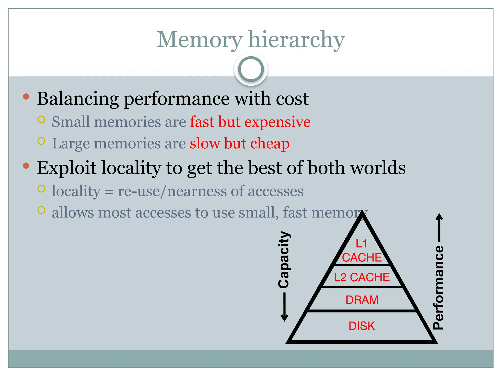
Balancingperformance with cost
Small memories are fast but expensive
Large memories are slow but cheap
Exploit locality to get the best of both worlds
locality = re-use/nearness of accesses
allows most accesses to use small, fast memory
Capacity
Performance
4.
An Example MemoryHierarchy
registers
on-chip L1
cache (SRAM)
main memory
(DRAM)
local secondary storage
(local disks)
Larger,
slower,
and
cheaper
(per byte)
storage
devices
remote secondary storage
(tapes, distributed file systems, Web servers)
Local disks hold files
retrieved from disks on
remote network servers.
Main memory holds disk
blocks retrieved from local
disks.
off-chip L2
cache (SRAM)
L1 cache holds cache lines retrieved
from the L2 cache memory.
CPU registers hold words retrieved
from L1 cache.
L2 cache holds cache lines
retrieved from main memory.
L0:
L1:
L2:
L3:
L4:
L5:
Smaller,
faster,
and
costlier
(per byte)
storage
devices
5.
Memory hierarchysystem consist of all storage
devices from auxiliary memory to main memory to
cache memory
As one goes down the hierarchy :
Cost per bit decreases.
Capacity increases.
Access time increases.
Frequency of access by the processor decreases.
6.
Main Memory
Itis the memory used to store programs and data
during the computer operation.
The principal technology is based on semiconductor
integrated circuits.
It consists of RAM and ROM chips.
RAM chips are available in two form static and
dynamic.
7.
RAM
A RAMchip is better suited for communication with the CPU if
it has one or more control inputs that select the chip when
needed
Read/write memory, that initially doesn’t contain any data
The computing system that it is used in usually stores data at
various locations to retrieve it latter from these locations
Its data pins are bidirectional (data can flow into or out of the
chip via these pins), as opposite to those of ROM that are output
only
It loses its data once the power is removed, so it is a volatile
memory
It has a chip select signal CS1,CS2’; When CS1 =1 and CS2’=0,
the chip is active for read and write operation.
When R=1, outputs data to the rest of the circuit
when W = 1 it inputs data from the rest of the circuit
8.
RAM types
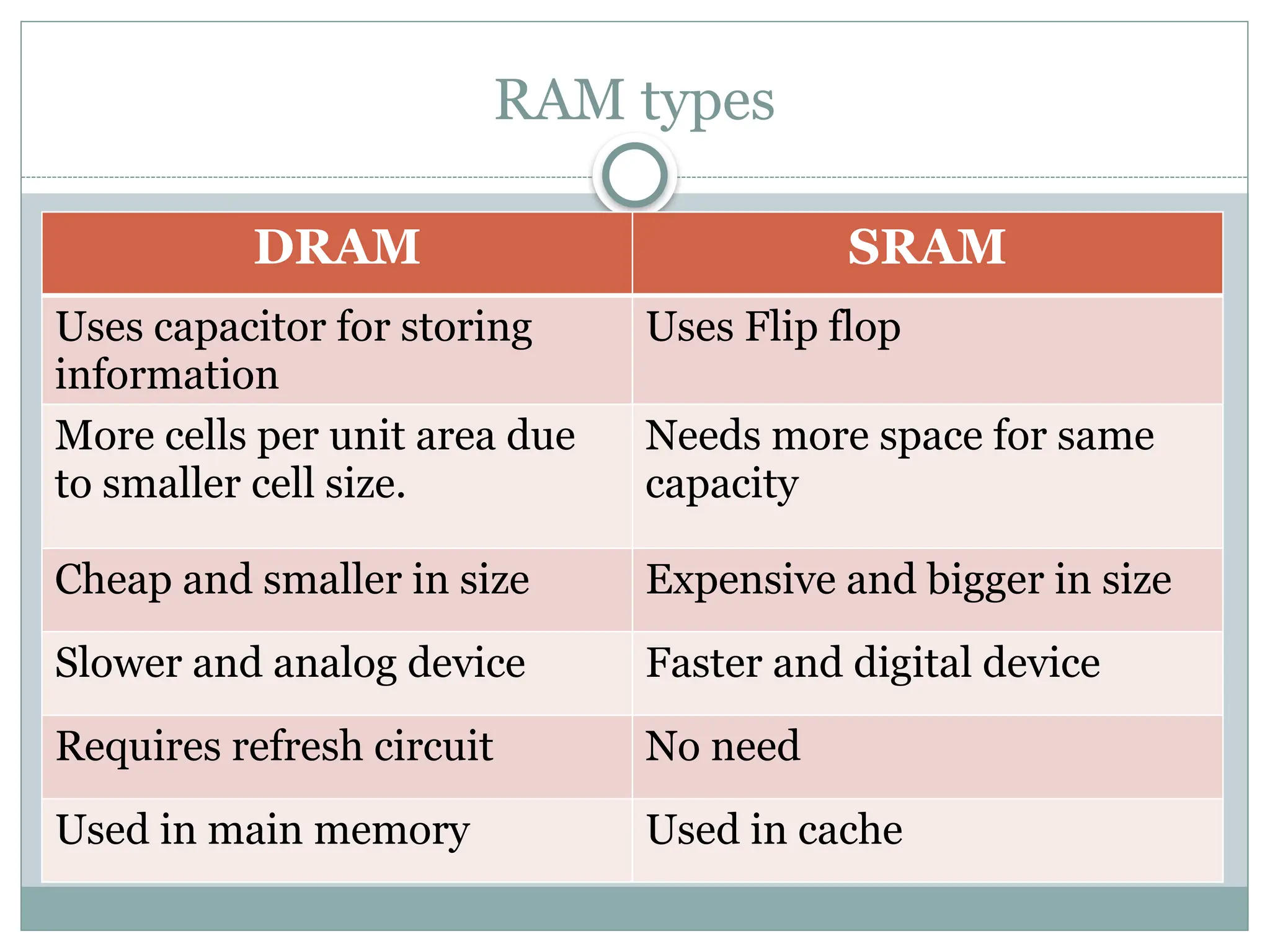
DRAM SRAM
Usescapacitor for storing
information
Uses Flip flop
More cells per unit area due
to smaller cell size.
Needs more space for same
capacity
Cheap and smaller in size Expensive and bigger in size
Slower and analog device Faster and digital device
Requires refresh circuit No need
Used in main memory Used in cache
10.
ROM
ROM isuses random access method.
It is used for storing programs that are permanent
and the tables of constants that do not change.
ROM store program called bootstrap loader whose
function is to start the computer software when the
power is turned on.
When the power is turned on, the hardware of the
computer sets the program counter to the first
address of the bootstrap loader.
12.
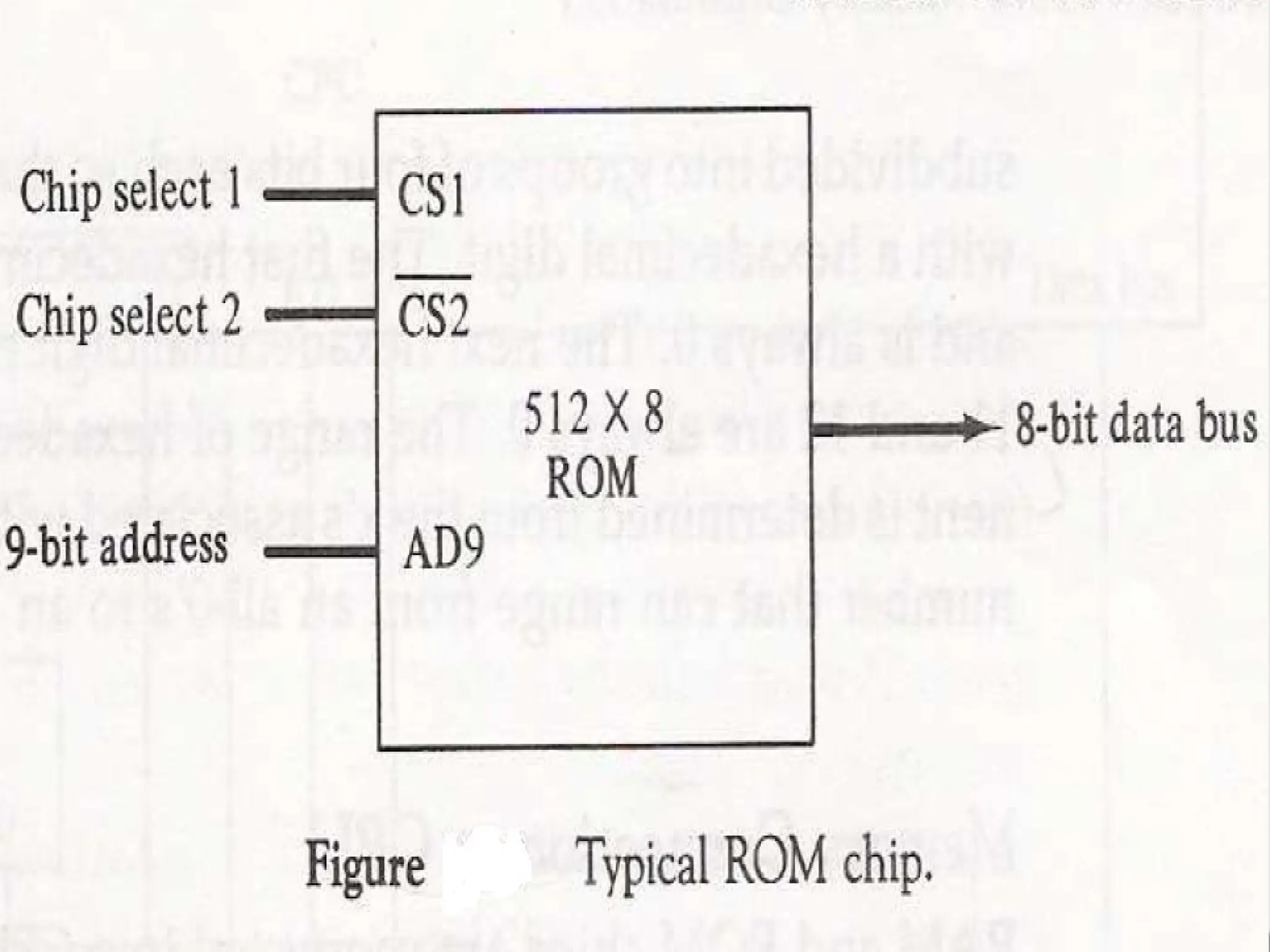
For thesame size chip it is possible to have more bits
of ROM than of RAM, because the internal binary
cells in ROM occupy less space than in RAM,
For this reason the diagram specifies 512 byte ROM
and 128 bytes RAM.
13.
Memory address Map
Designer must specify the size and the type(RAM or
ROM) of memory to be used for particular
application.
The addressing of the memory is then established by
means of table called memory address map that
specifies the memory address assign to each chip.
Let us consider an example in which computer needs
512 bytes of RAM and ROM as well and we have to
use the chips of size 128 bytes for RAM and 512 bytes
for ROM.
16.
Associative Memory
Tosearch particular data in memory, data is read
from certain address and compared if the match is
not found content of the next address is accessed and
compared.
This goes on until required data is found. The
number of access depend on the location of data and
efficiency of searching algorithm.
The searching time can be reduced if data is searched
on the basis of content.
17.
A memoryunit accessed by content is called
associative memory or content addressable
memory(CAM)
This type of memory is accessed simultaneously and
in parallel on the basis of data content.
Memory is capable of finding empty unused location
to store the word.
These are used in the application where search time
is very critical and must be very short.
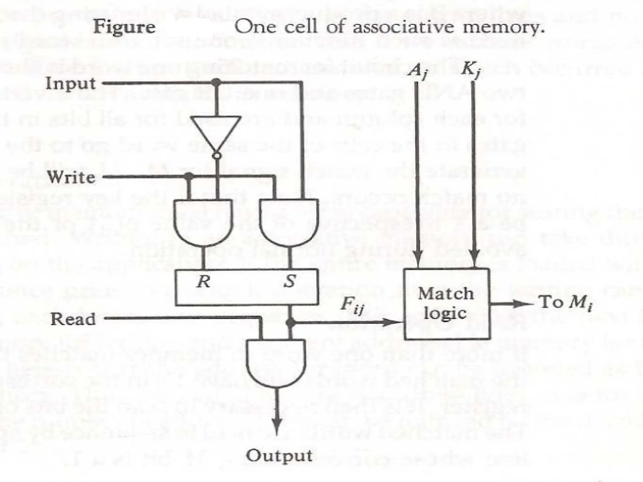
19.
Associative Memory
Itconsists memory array of m words with n bits per
words
Argument register A and key register K have n bits
one for each bit of word.
Match register has m bits, one for each memory
word.
Each word in memory is compared in parallel with
the content of the A register. For the word that
match corresponding bit in the match register is set.
20.
Associative Memory
Keyregister provide the mask for choosing the
particular field in A register.
The entire content of A register is compared if key
register content all 1.
Otherwise only bit that have 1 in key register are
compared.
If the compared data is matched corresponding bits
in the match register are set.
Reading is accomplished by sequential access in
memory for those words whose bit are set.
Match Logic
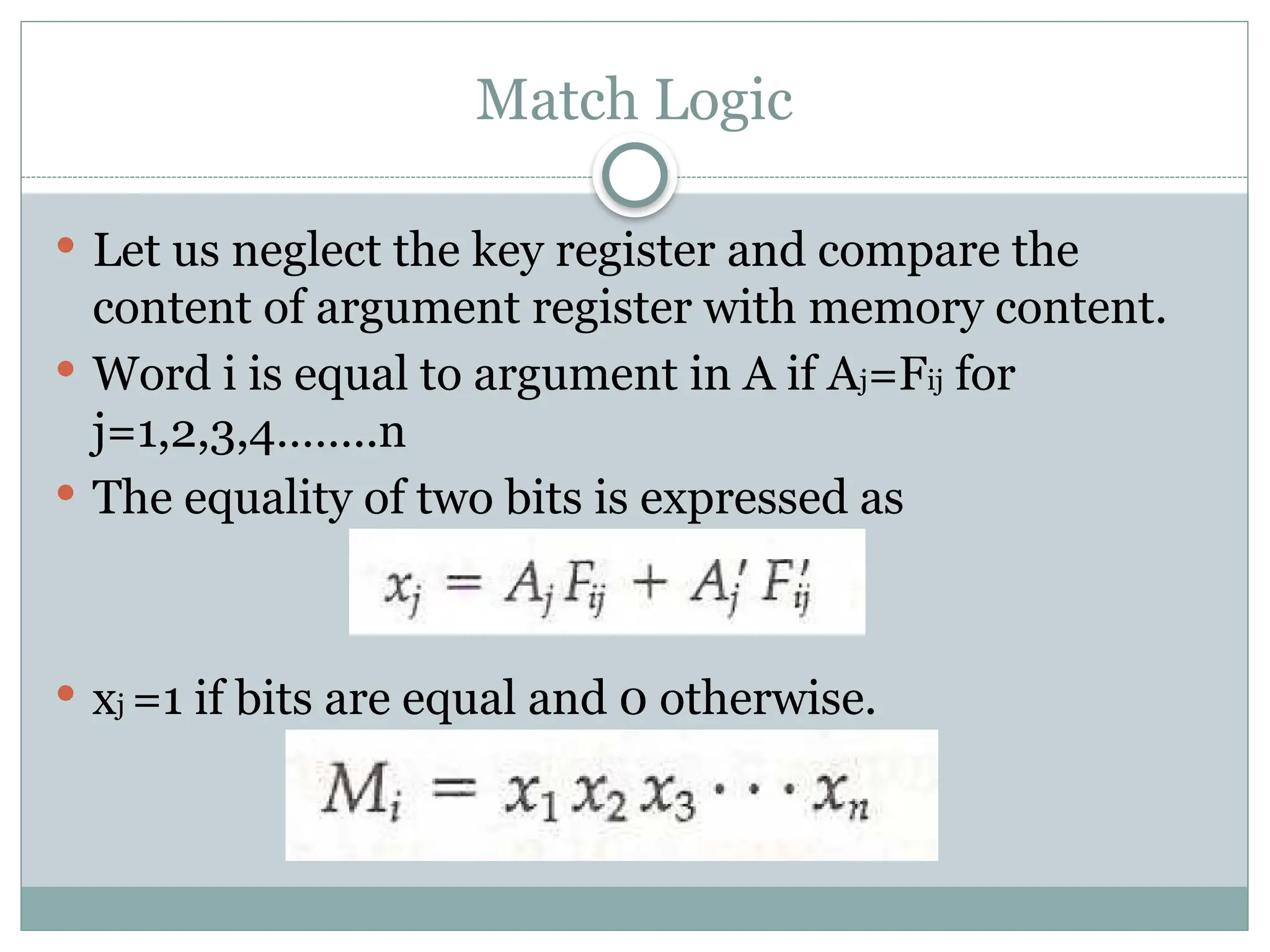
Letus neglect the key register and compare the
content of argument register with memory content.
Word i is equal to argument in A if Aj=Fij for
j=1,2,3,4……..n
The equality of two bits is expressed as
xj =1 if bits are equal and 0 otherwise.
25.
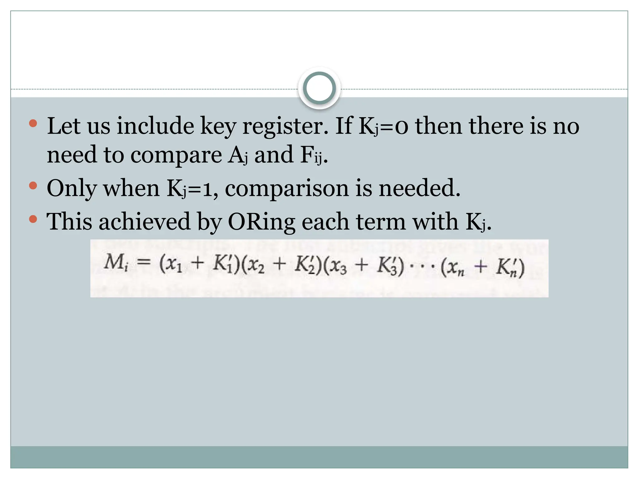
Let usinclude key register. If Kj=0 then there is no
need to compare Aj and Fij.
Only when Kj=1, comparison is needed.
This achieved by ORing each term with Kj.
27.
Read Operation
Ifmore than one word match with the content, all
the matched words will have 1 in the corresponding
bit position in match register.
Matched words are then read in sequence by
applying a read signal to each word line.
In most application, the associative memory stores a
table with no two identical items under a given key.
28.
Write Operation
Ifthe entire memory is loaded with new information
at once prior to search operation then writing can be
done by addressing each location in sequence.
Tag register contain as many bits as there are words
in memory.
It contain 1 for active word and 0 for inactive word.
If the word is to be inserted, tag register is scanned
until 0 is found and word is written at that position
and bit is change to 1.
29.
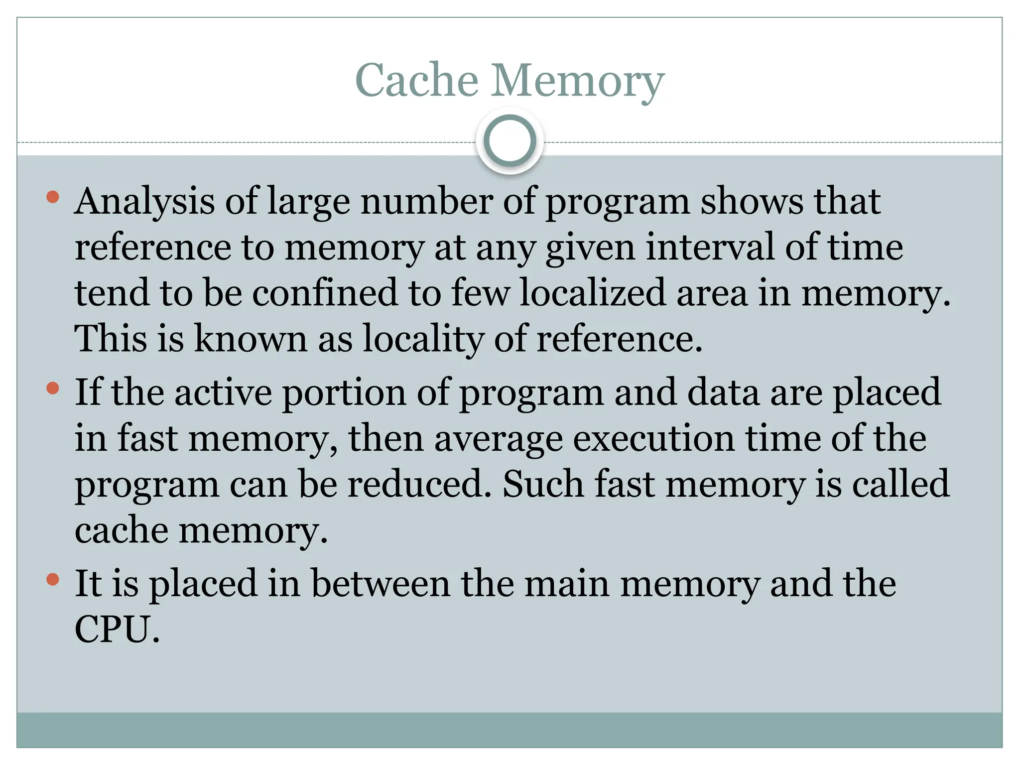
Cache Memory
Analysisof large number of program shows that
reference to memory at any given interval of time
tend to be confined to few localized area in memory.
This is known as locality of reference.
If the active portion of program and data are placed
in fast memory, then average execution time of the
program can be reduced. Such fast memory is called
cache memory.
It is placed in between the main memory and the
CPU.
31.
Cache Memory
Whenthe CPU need to access the memory it first
search in cache. If word is found, it is read.
If the word is not found, it is read from main
memory and a block of data is transferred from main
memory to cache which contain the current word.
If the word is found in cache, it is said hit. If the
word is not found, it is called miss.
Performance of cache is measured in terms of hit
ratio which ratio of total hit to total memory access
by CPU.
32.
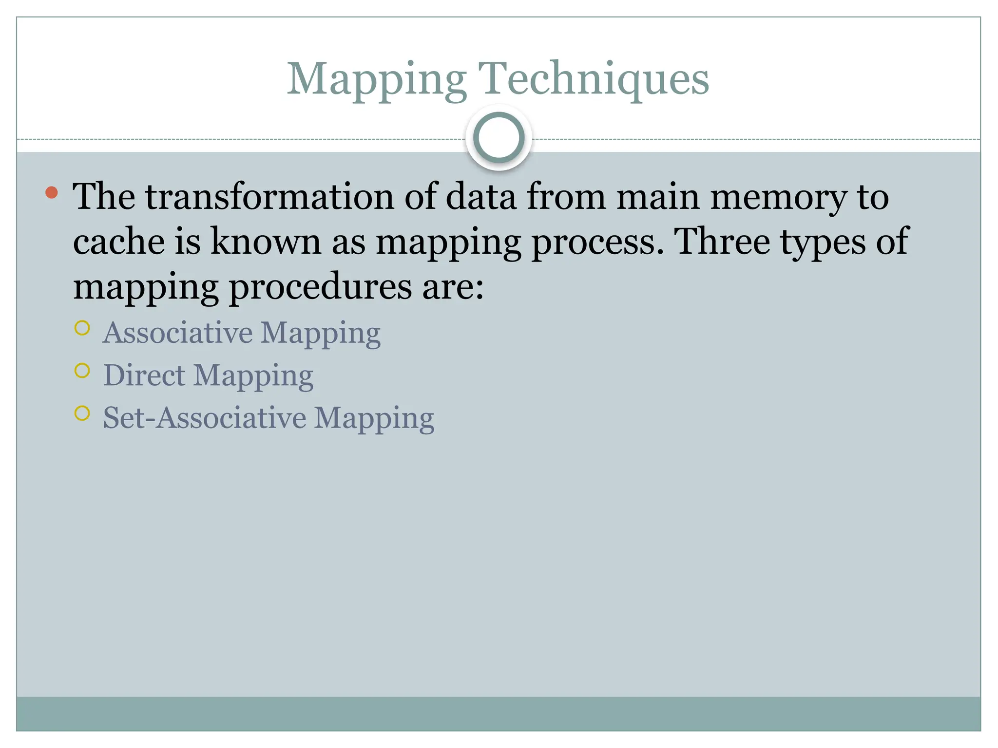
Mapping Techniques
Thetransformation of data from main memory to
cache is known as mapping process. Three types of
mapping procedures are:
Associative Mapping
Direct Mapping
Set-Associative Mapping
33.
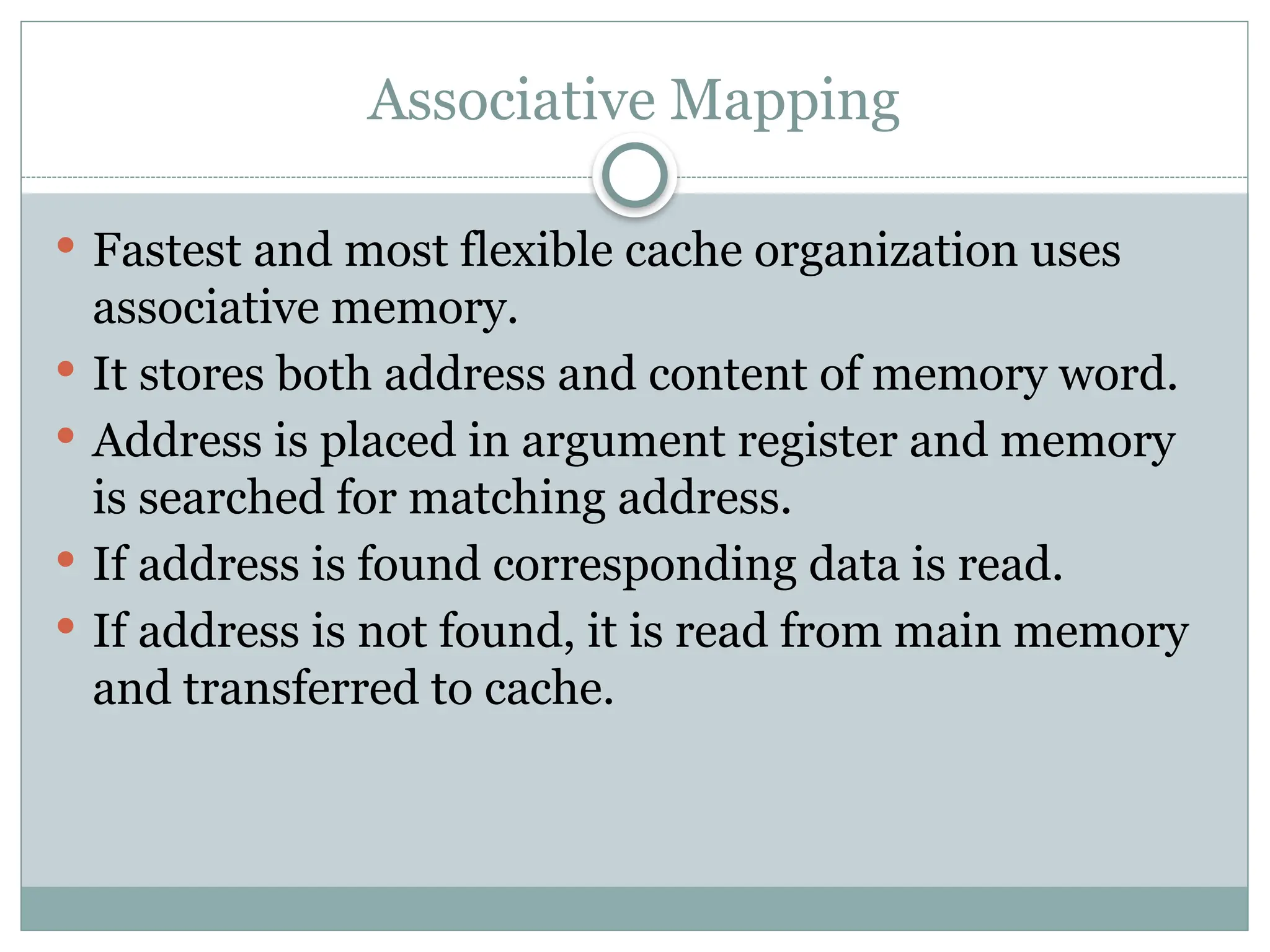
Associative Mapping
Fastestand most flexible cache organization uses
associative memory.
It stores both address and content of memory word.
Address is placed in argument register and memory
is searched for matching address.
If address is found corresponding data is read.
If address is not found, it is read from main memory
and transferred to cache.
34.
If thecache is full, an address- word pair must be
displaced.
Various algorithm are used to determine which pair
to displace. Some of them are FIFO(First In First
Out), LRU(Least Recently Used) etc.
35.
Direct Mapping
CPUaddress is divided into two fields tag and index.
Index field is required to access cache memory and
total address is used to access main memory.
If there are 2^k words in cache and 2^n words in
main memory, then n bit memory address is divided
into two parts. k bits for index field and n-k bits for
tag field.
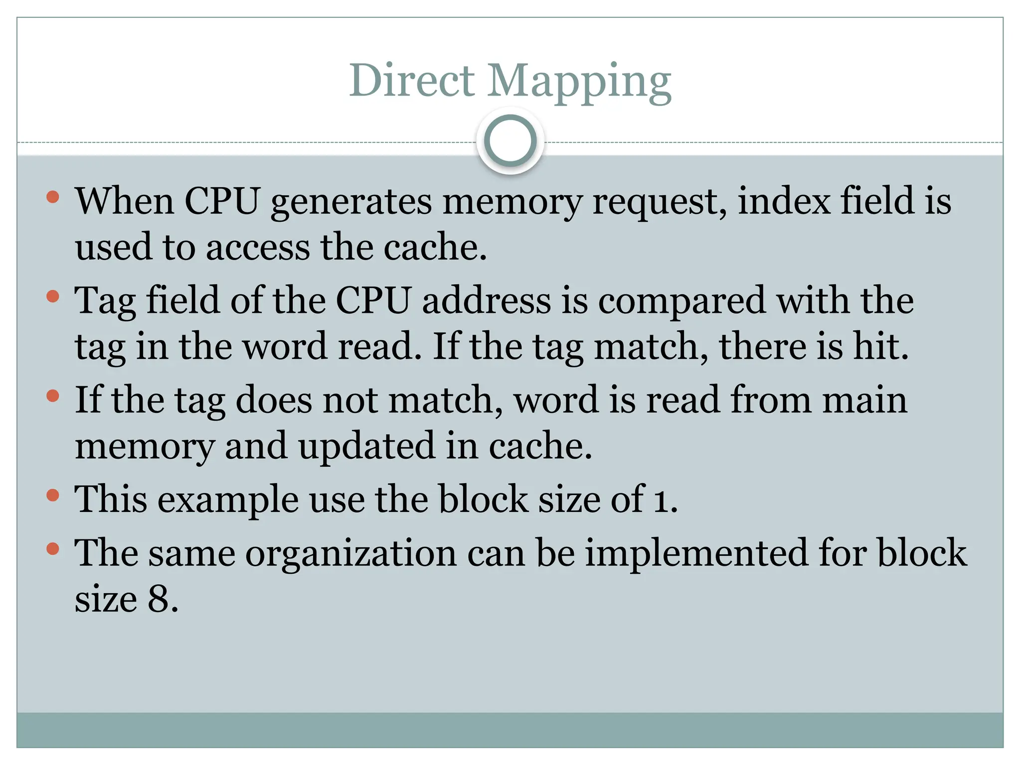
Direct Mapping
WhenCPU generates memory request, index field is
used to access the cache.
Tag field of the CPU address is compared with the
tag in the word read. If the tag match, there is hit.
If the tag does not match, word is read from main
memory and updated in cache.
This example use the block size of 1.
The same organization can be implemented for block
size 8.
39.
Direct Mapping
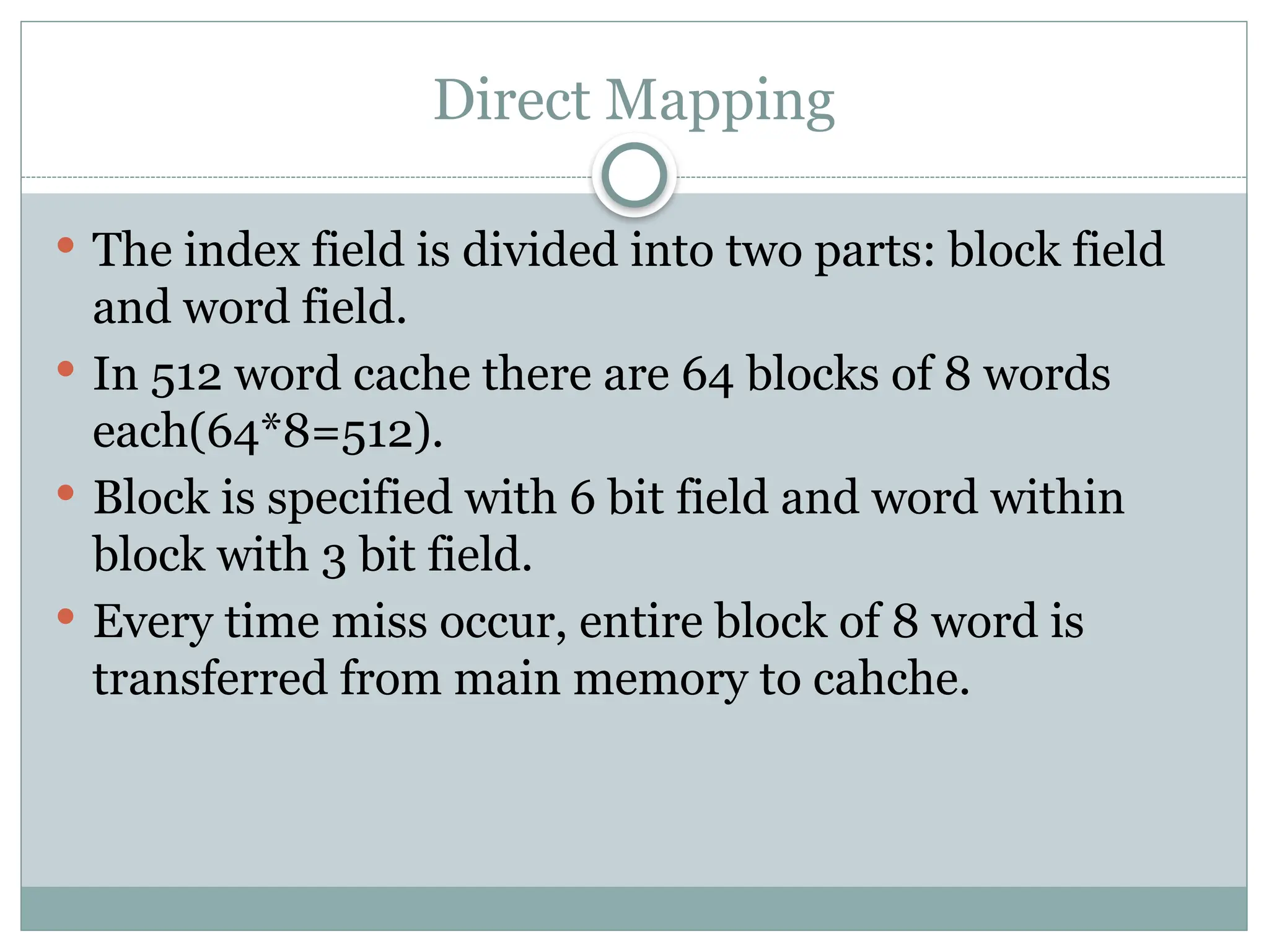
Theindex field is divided into two parts: block field
and word field.
In 512 word cache there are 64 blocks of 8 words
each(64*8=512).
Block is specified with 6 bit field and word within
block with 3 bit field.
Every time miss occur, entire block of 8 word is
transferred from main memory to cahche.
41.
Set-Associative Mapping
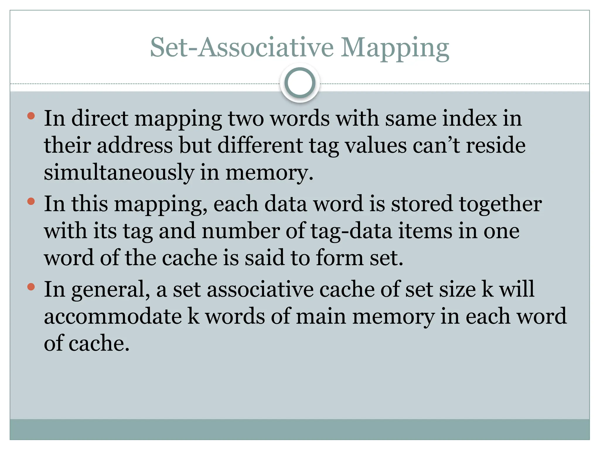
Indirect mapping two words with same index in
their address but different tag values can’t reside
simultaneously in memory.
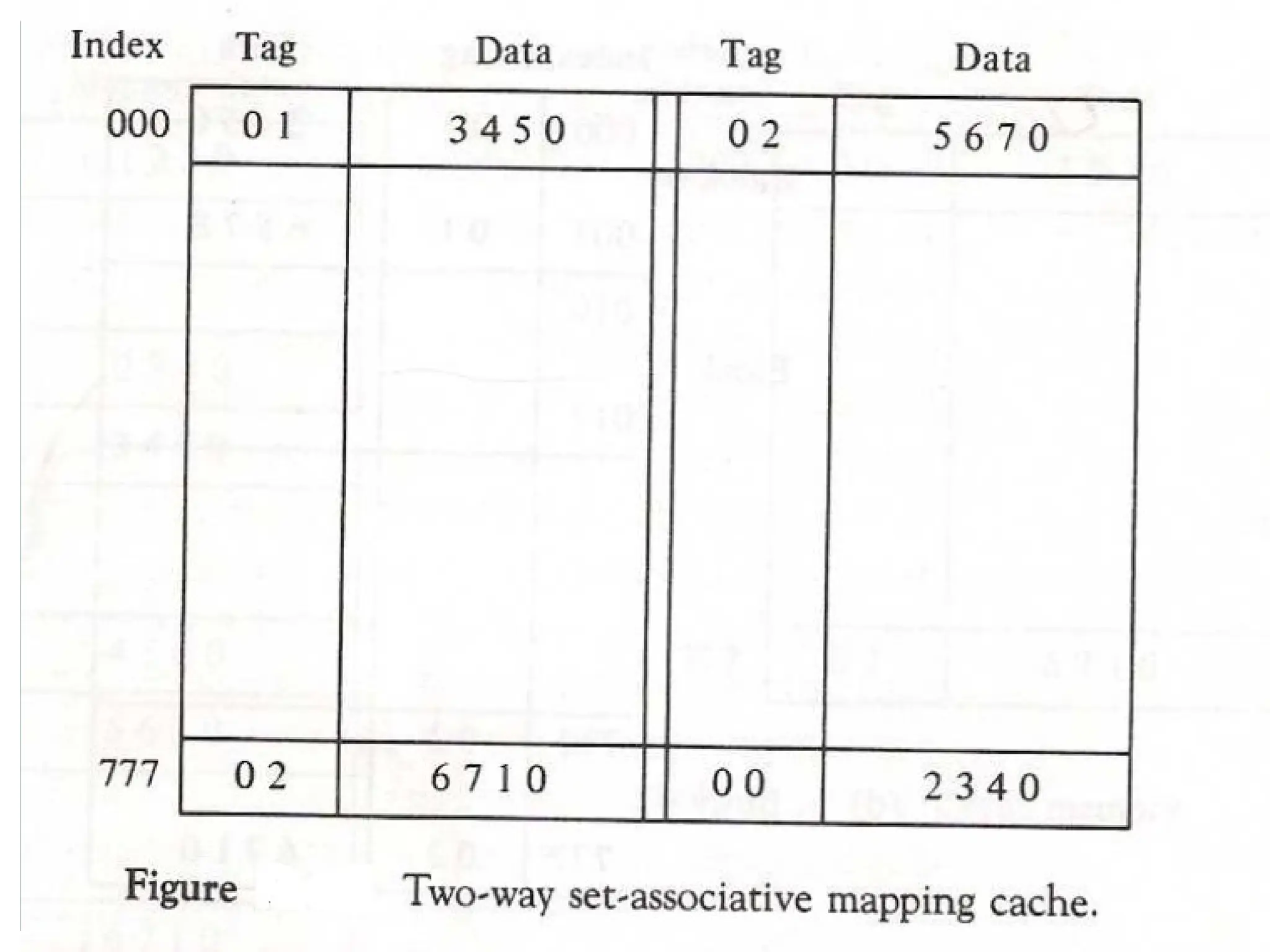
In this mapping, each data word is stored together
with its tag and number of tag-data items in one
word of the cache is said to form set.
In general, a set associative cache of set size k will
accommodate k words of main memory in each word
of cache.
43.
Set-Associative Mapping
Whena miss occur and the set is full, one of the tag
data item is replaced with new value using various
algorithm.
44.
Writing into Cache
Writing into cache can be done in two ways:
Write through
Write Back
In write through, whenever write operation is
performed in cache memory, main memory is also
updated in parallel with the cache.
In write back, only cache is updated and marked by
the flag. When the word is removed from cache, flag
is checked if it is set the corresponding address in
main memory is updated.
45.
Cache Initialization
Whenpower is turned on, cache contain invalid data
indicated by valid bit value 0.
Valid bit of word is set whenever the word is read
from main memory and updated in cache.
If valid bit is 0, new word automatically replace the
invalid data.
46.
Virtual Memory
Virtualmemory is a concept used in computer that
permit the user to construct a program as though
large memory space is available equal to auxiliary
memory.
It give the illusion that computer has large memory
even though computer has relatively small main
memory.
It has mechanism that convert generated address
into correct main memory address.
47.
Virtual Memory: BasicIdea
Divide memory (virtual and physical) into fixed size
blocks
Pages in Virtual space, Frames in Physical space
Page size = Frame size
Page size is a power of 2: page size = 2k
All pages in the virtual address space are contiguous
Pages can be mapped into physical Frames in any order
Some of the pages are in main memory (DRAM),
some of the pages are on disk
All programs are written using Virtual Memory Address
Space
The hardware does on-the-fly translation between virtual
and physical address spaces
Use a Page Table to translate between Virtual and Physical addresses
48.
Main memorycan act as a cache for the secondary storage (disk)
Advantages:
illusion of having more physical memory
program relocation
protection
Virtual Memory
Virtual Addresses Physical Addresses
Disk Addresses
Address
Translation
49.
Address Space andMemory Space
An address used by the programmer is called virtual
address and set of such address is called address
space.
An address in main memory is called physical
address. The set of such location is called memory
space.
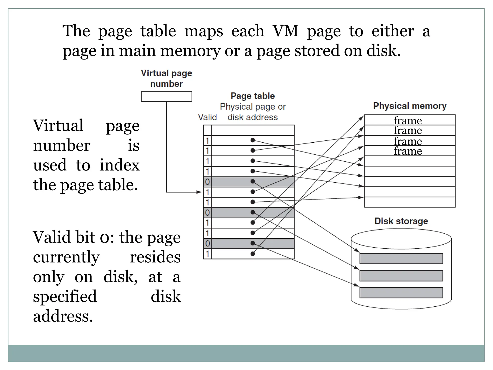
The page tablemaps each VM page to either a
page in main memory or a page stored on disk.
frame
frame
frame
frame
Virtual page
number is
used to index
the page table.
Valid bit 0: the page
currently resides
only on disk, at a
specified disk
address.
52.
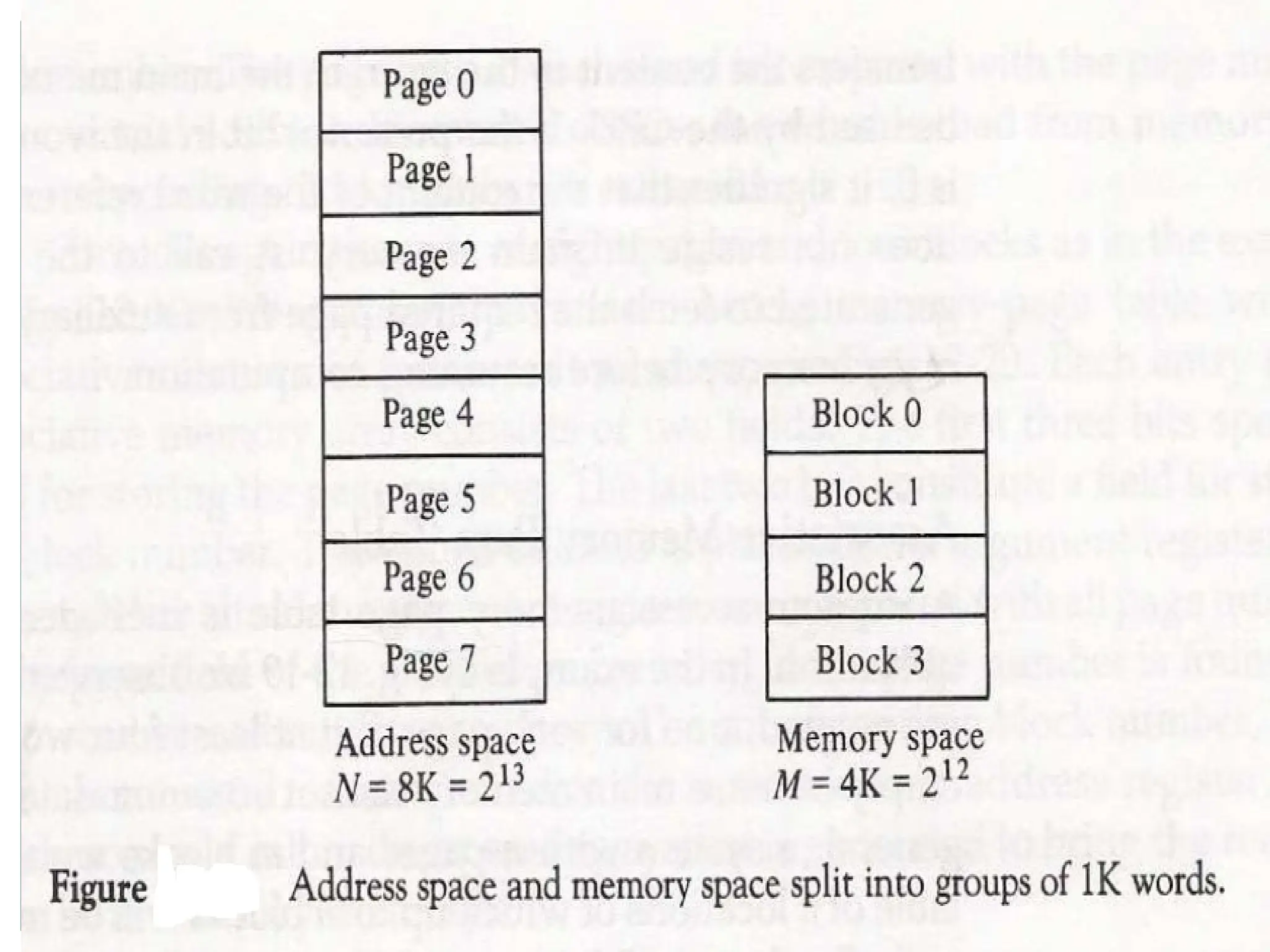
Address Mapping UsingPages
The main memory is broken down into groups of
equal size called blocks.
Term pages refers to groups of address space of same
size.
Although page and block are of equal size, page refer
to organization of address space and block represent
the organization of memory space.
The term page frame is sometimes used to denote
block.
57.
The programis executed from main memory until
page required is not available.
If page is not available, this condition is called page
fault. When it occurs, present program is suspended
until the page required is brought into main
memory.
If main memory is full, pages to remove is
determined from the replacement algorithm used.
Page Replacement
58.
PAGE REPLACEMENT
Modified pagefault service routine
Decision on which page to displace to make room for
an incoming page when no free frame is available
1. Find the location of the desired page on the backing store
2. Find a free frame
- If there is a free frame, use it
- Otherwise, use a page-replacement algorithm to select a victim frame
- Write the victim page to the backing store
3. Read the desired page into the (newly) free frame
4. Restart the user process
2
f 0 v i
f v
frame
valid/
invalid bit
page table
change to
invalid
4
reset page
table for
new page
victim
1
swap
out
victim
page
3
swap
desired
page in
backing store
physical memory
59.
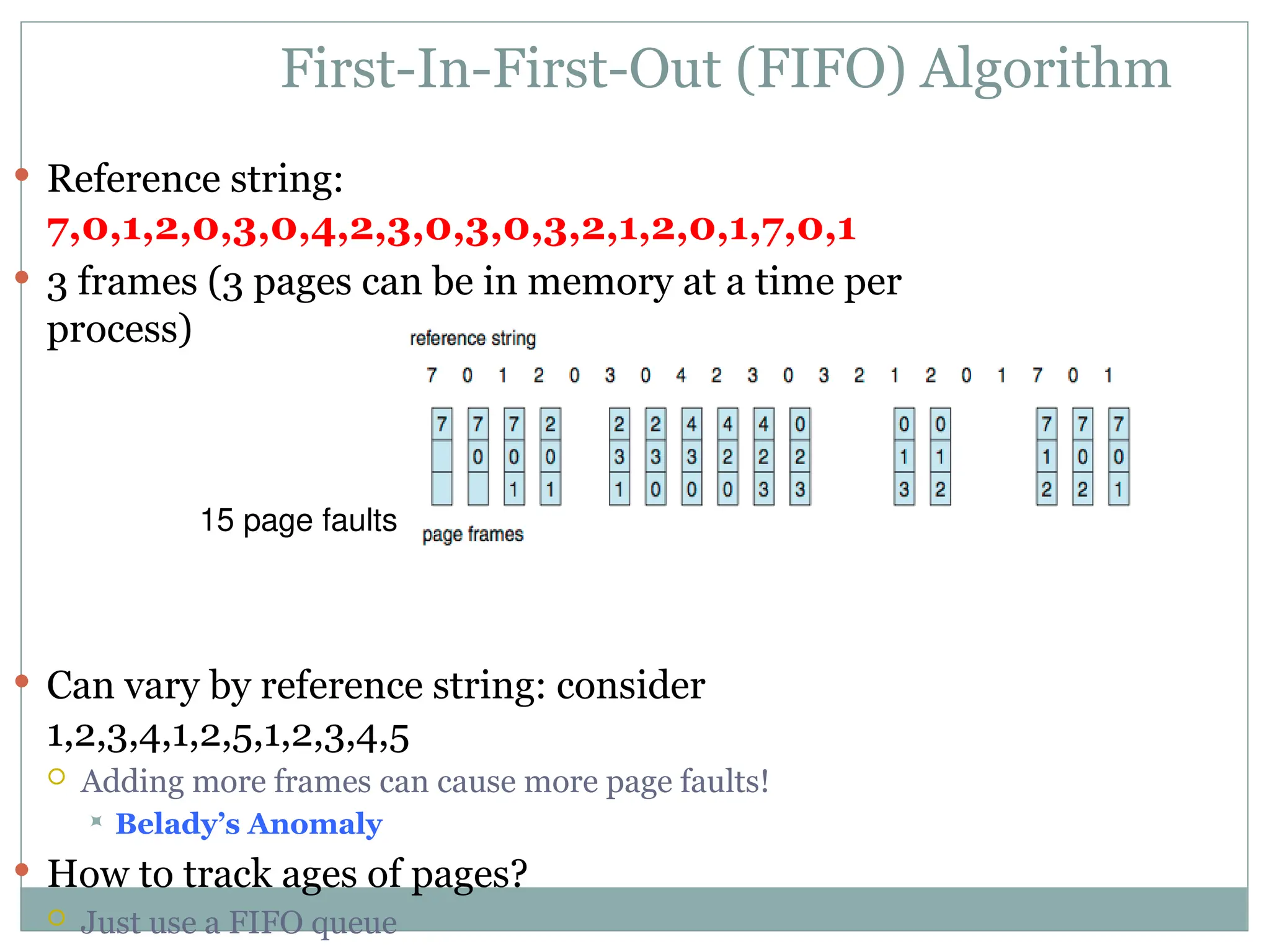
First-In-First-Out (FIFO) Algorithm
Reference string:
7,0,1,2,0,3,0,4,2,3,0,3,0,3,2,1,2,0,1,7,0,1
3 frames (3 pages can be in memory at a time per
process)
Can vary by reference string: consider
1,2,3,4,1,2,5,1,2,3,4,5
Adding more frames can cause more page faults!
Belady’s Anomaly
How to track ages of pages?
Just use a FIFO queue
15 page faults
60.
Optimal Algorithm
Replacepage that will not be used for longest
period of time
9 is optimal for the example
How do you know this?
Can’t read the future
Used for measuring how well your algorithm
performs
61.
Least Recently Used(LRU) Algorithm
Use past knowledge rather than future
Replace page that has not been used in the most amount of time
Associate time of last use with each page
12 faults – better than FIFO but worse than OPT
Generally good algorithm and frequently used
But how to implement?