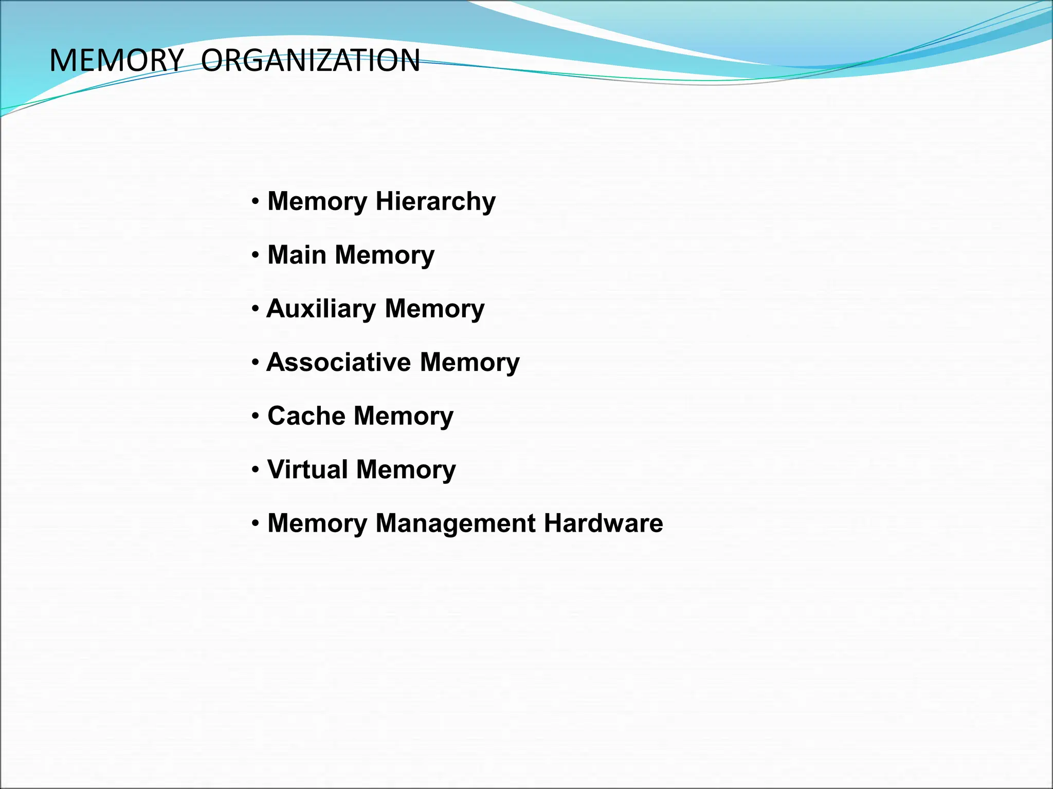
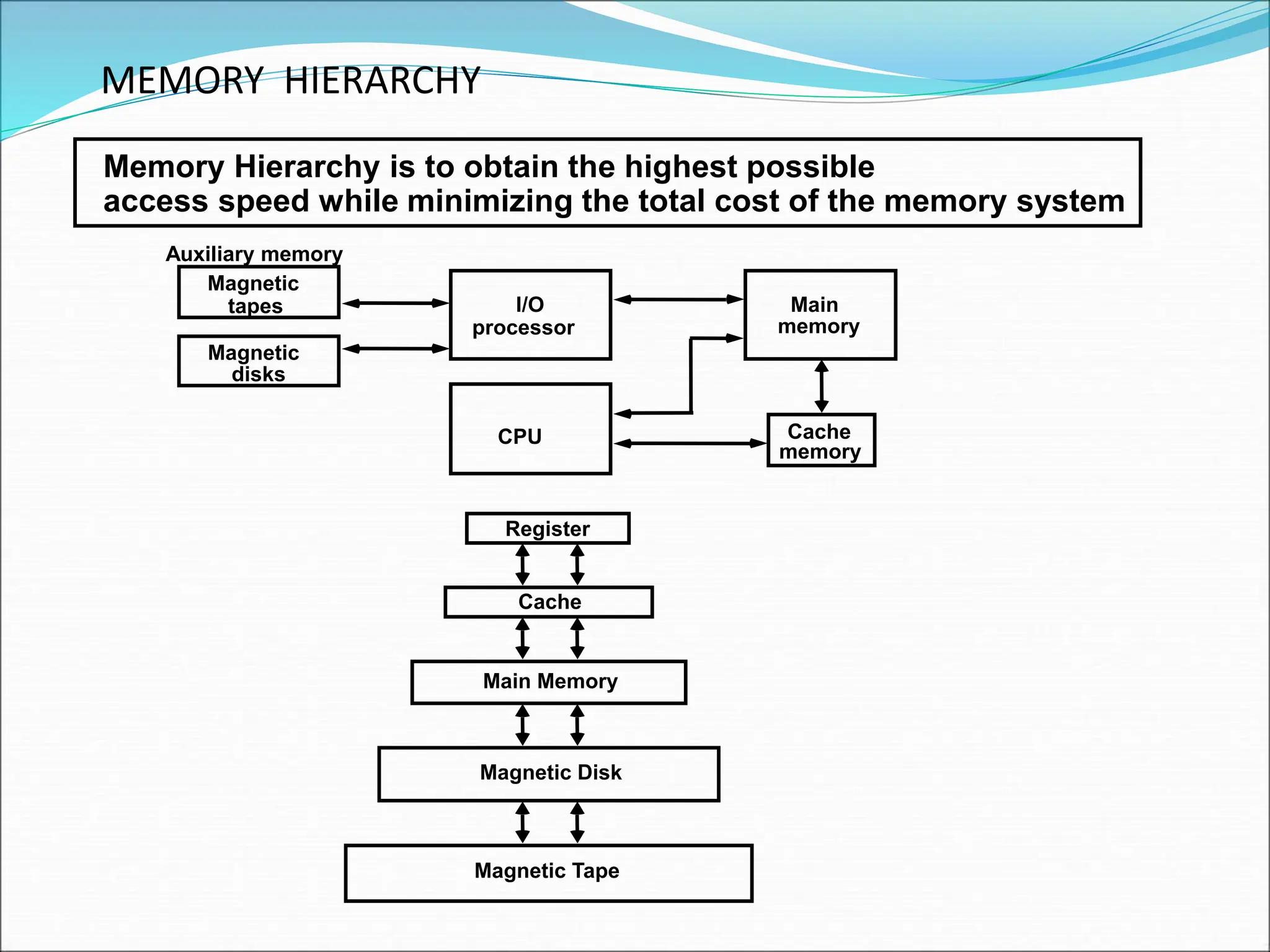
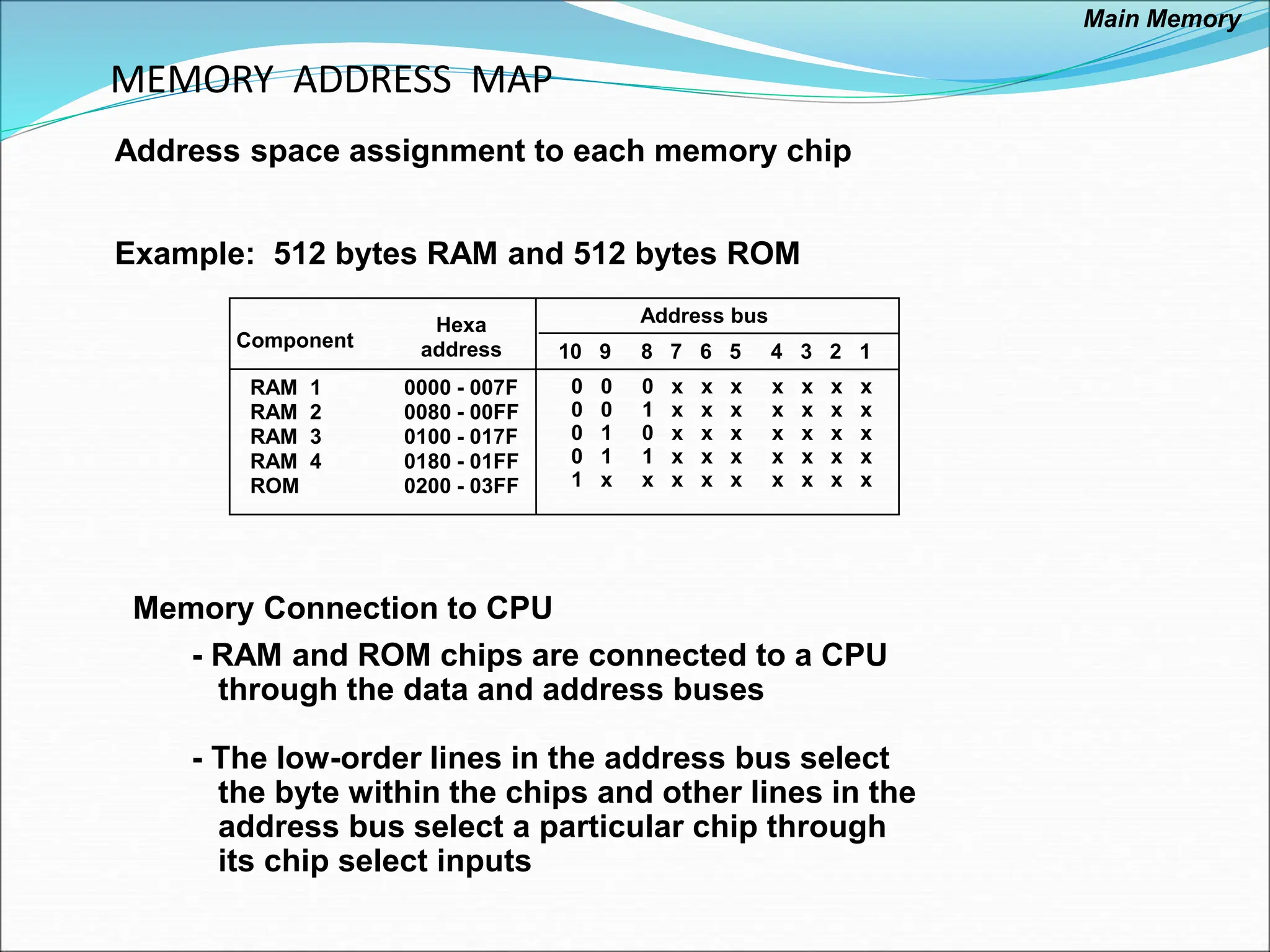
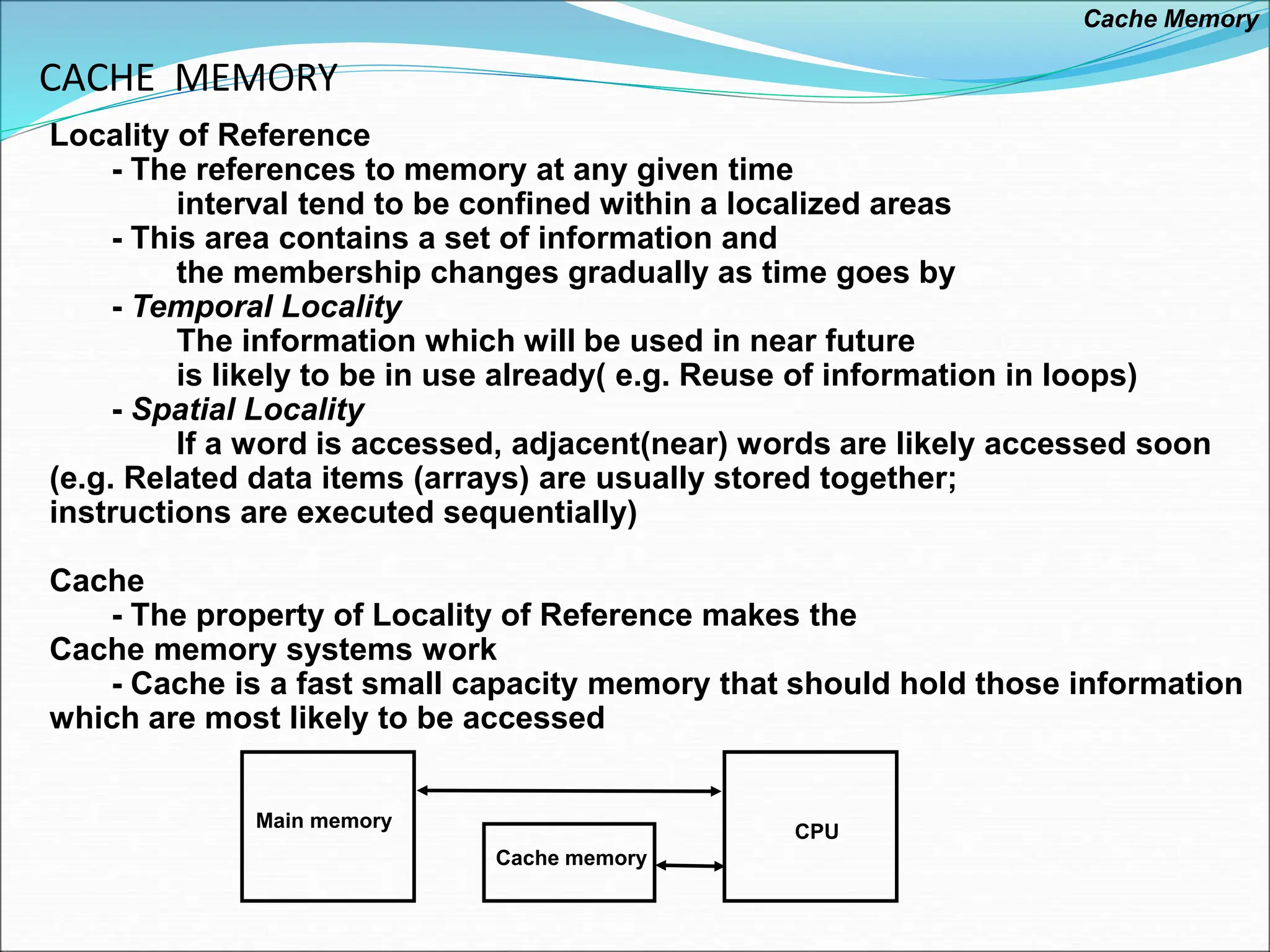
The document discusses different types of computer memory and how they are organized in a memory hierarchy. It describes main memory, auxiliary memory like magnetic disks, cache memory, and virtual memory. The memory hierarchy is designed to obtain the highest possible access speed while minimizing total memory system cost by placing faster but smaller memories closer to the CPU. Cache memory exploits locality of reference to improve average memory access time.

![ASSOCIATIVE MEMORY
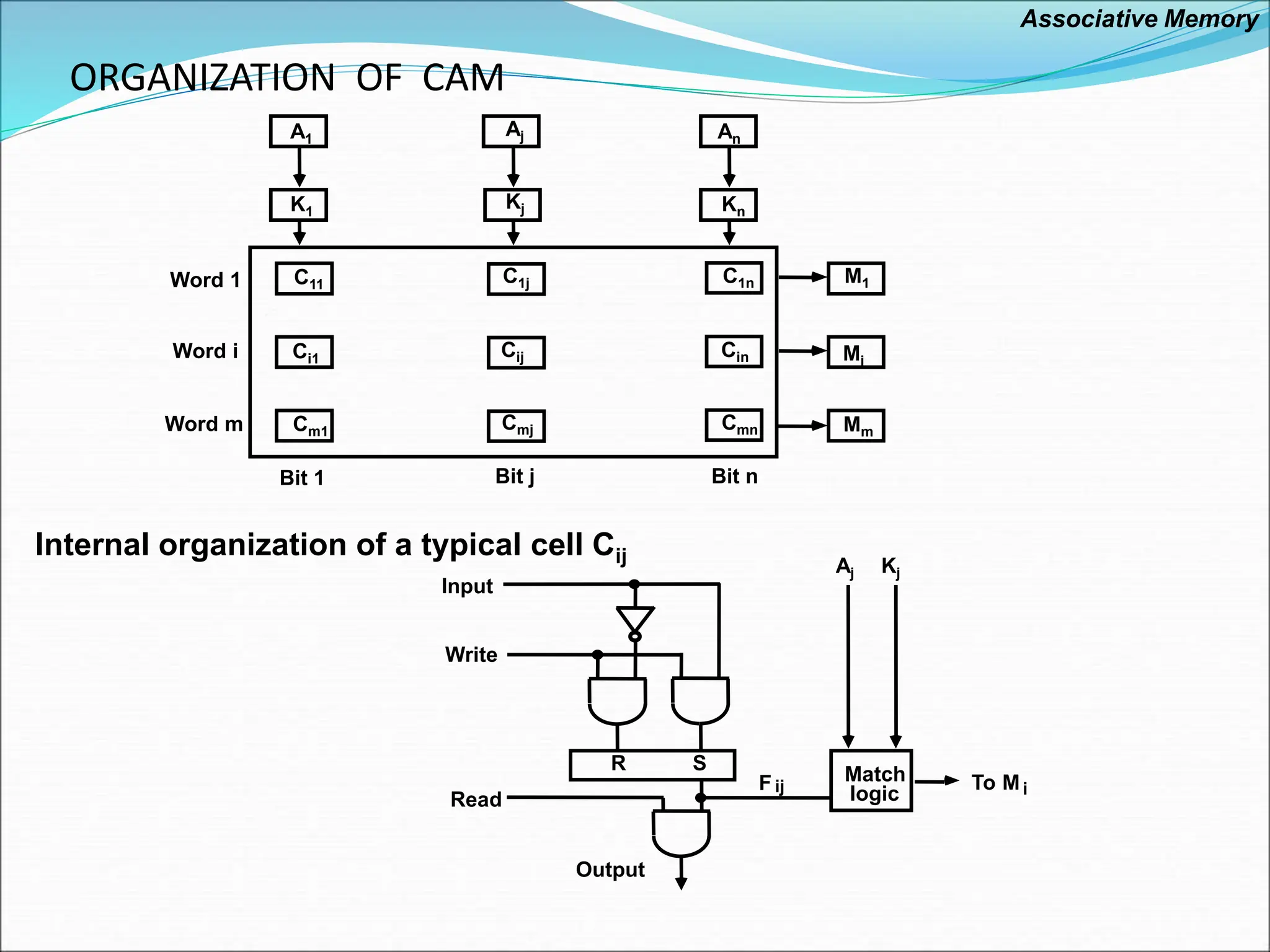
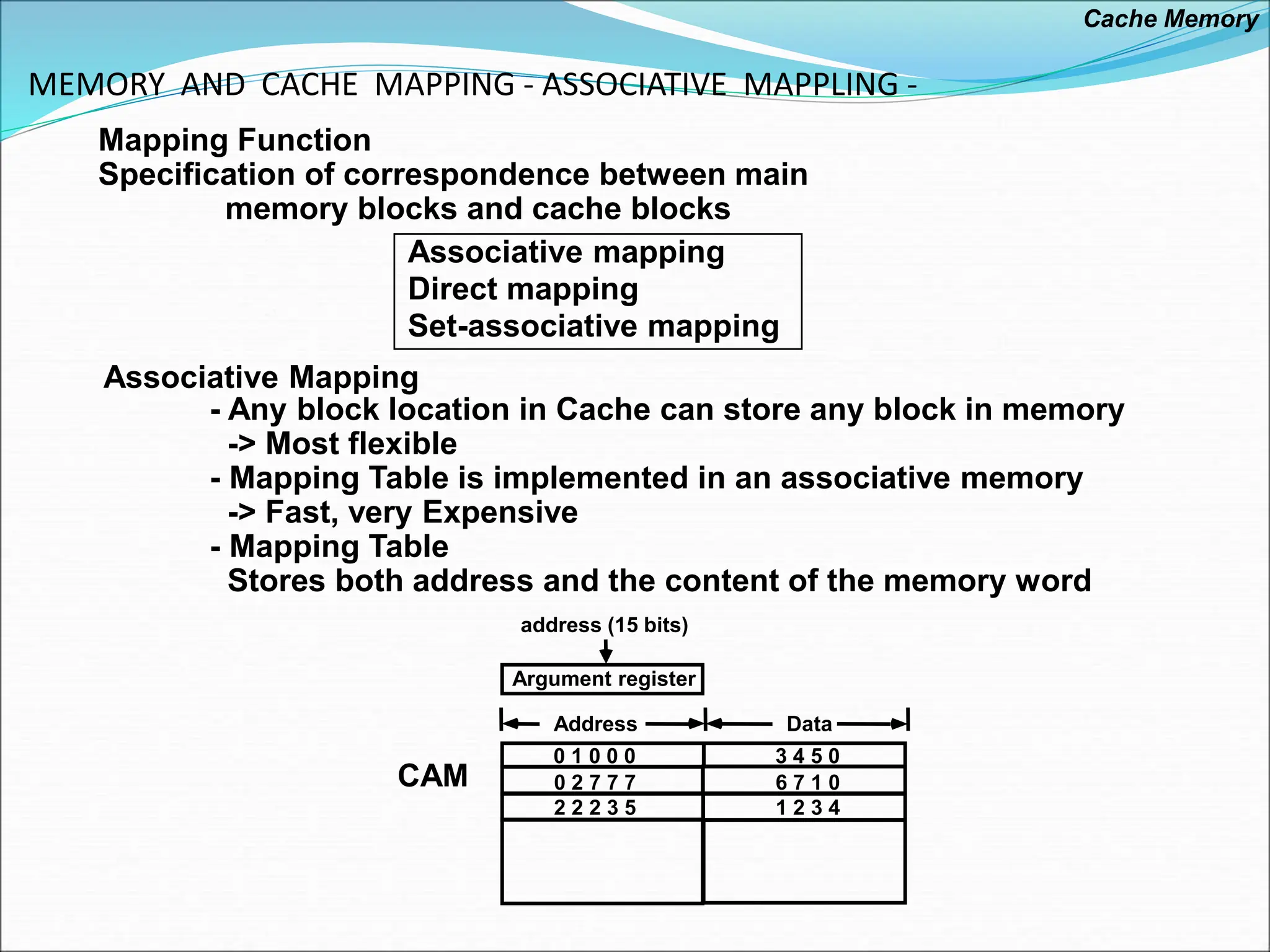
- Accessed by the content of the data rather than by an address
- Also called Content Addressable Memory (CAM)
Hardware Organization Argument register(A)
Key register (K)
Associative memory
array and logic
m words
n bits per word
Match
register
Input
Read
Write
M
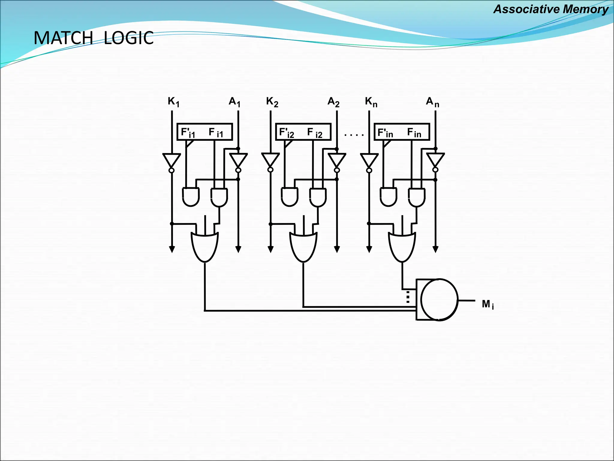
- Compare each word in CAM in parallel with the
content of A(Argument Register)
- If CAM Word[i] = A, M(i) = 1
- Read sequentially accessing CAM for CAM Word(i) for M(i) = 1
- K(Key Register) provides a mask for choosing a
particular field or key in the argument in A
(only those bits in the argument that have 1’s in
their corresponding position of K are compared)
Associative Memory](https://image.slidesharecdn.com/memoryorganization23-24-240415075423-23ab5a97/75/Memory-Organizationsssssssssssssssss-ppt-7-2048.jpg)
 to CPU
- If not match -> Miss
M[tag;INDEX] <- Cache[INDEX](data)
Cache[INDEX] <- (TAG;M[TAG; INDEX])
CPU <- Cache[INDEX](data)
Index tag data
000 0 1 3 4 5 0
007 0 1 6 5 7 8
010
017
770 0 2
777 0 2 6 7 1 0
Block 0
Block 1
Block 63
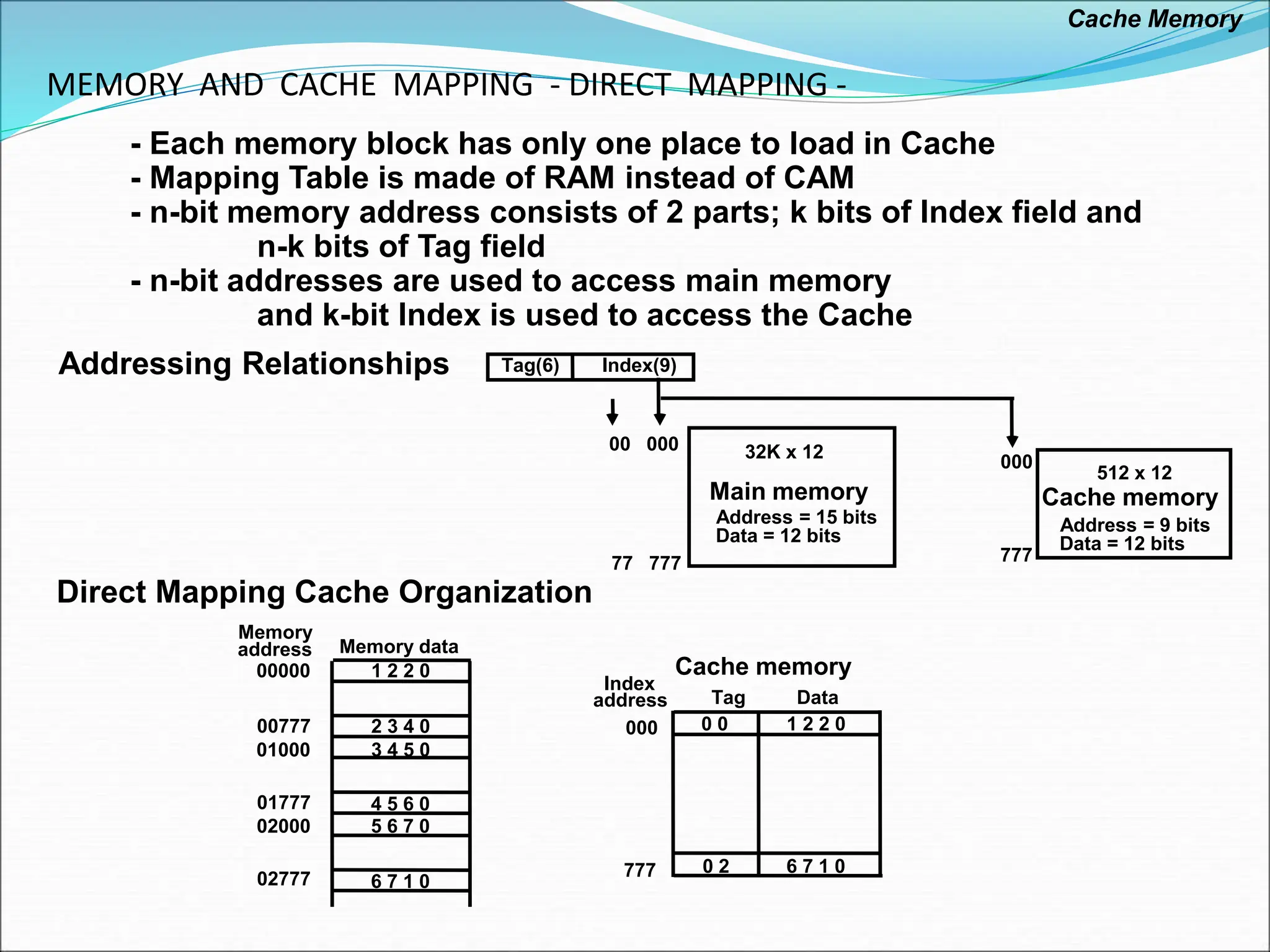
Tag Block Word
6 6 3
INDEX
Cache Memory](https://image.slidesharecdn.com/memoryorganization23-24-240415075423-23ab5a97/75/Memory-Organizationsssssssssssssssss-ppt-14-2048.jpg)
![MEMORY AND CACHE MAPPING - SET ASSOCIATIVE MAPPING -
Set Associative Mapping Cache with set size of two
- Each memory block has a set of locations in the Cache to load
Index Tag Data
000 0 1 3 4 5 0 0 2 5 6 7 0
Tag Data
777 0 2 6 7 1 0 0 0 2 3 4 0
Operation
- CPU generates a memory address(TAG; INDEX)
- Access Cache with INDEX, (Cache word = (tag 0, data 0); (tag 1, data 1))
- Compare TAG and tag 0 and then tag 1
- If tag i = TAG -> Hit, CPU <- data i
- If tag i TAG -> Miss,
Replace either (tag 0, data 0) or (tag 1, data 1),
Assume (tag 0, data 0) is selected for replacement,
(Why (tag 0, data 0) instead of (tag 1, data 1) ?)
M[tag 0, INDEX] <- Cache[INDEX](data 0)
Cache[INDEX](tag 0, data 0) <- (TAG, M[TAG,INDEX]),
CPU <- Cache[INDEX](data 0)
Cache Memory](https://image.slidesharecdn.com/memoryorganization23-24-240415075423-23ab5a97/75/Memory-Organizationsssssssssssssssss-ppt-15-2048.jpg)