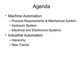
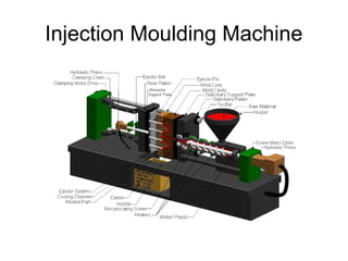
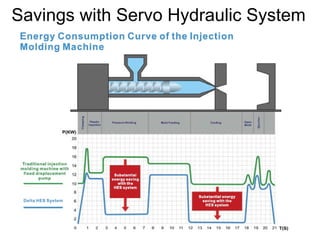
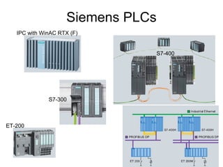
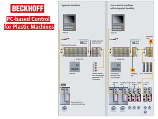
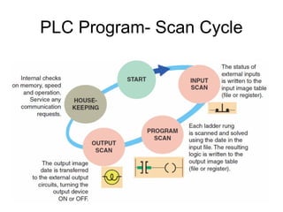
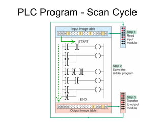
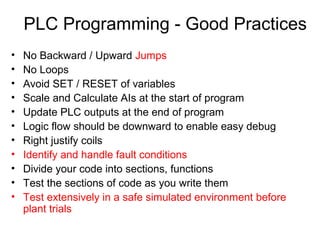
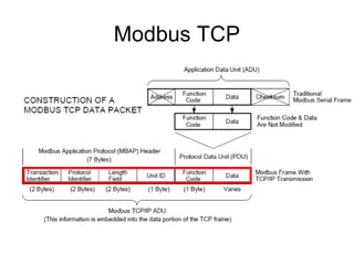
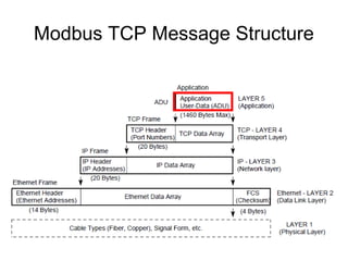
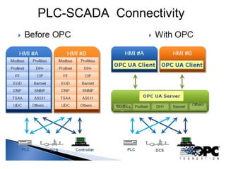
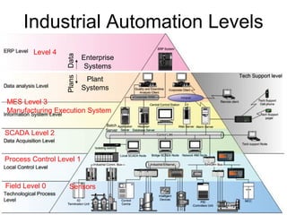
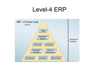
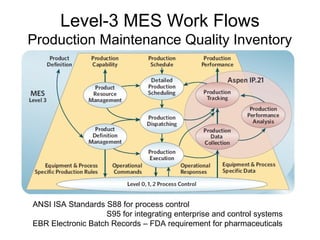
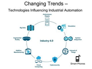
2. Agenda
• Machine Automation
– Process Requirements & Mechanical System
– Hydraulic System
– Electrical and Electronics Systems
• Industrial Automation
– Hierarchy
– New Trends
5. Clamping - Toggle & Hydraulic
Clamp
Stroke
• Clamping Speed and Pressure Profile.
• Mould Safety to prevent Mould Closing in case of un-ejected product in the mould
9. MotorPump
Pressure Control Valve
Flow Control Valve FilterOrientation Control Valve
Oil Cylinder
Oil Tank
Set-points
Sensing
Control
Controller
Pressure Relief
Valve
Conventional Proportional
Hydraulic System
• Fixed Displacement
• AC / DC Coils
14. Advantages of Servo Hydraulic System
• Energy Savings
• Fewer Valves
– Conventional Flow and Pressure Control Valves are
reduced
• Lower Heating of Oil
– Lower Cooling Power
– Components have longer life
– Better Control
• Lower Noise
15. Safety Around Hydraulic Systems
• Maintain Oil Quality
– Valve Jamming (Action? Mitigation?)
• Maintain Oil Temperature
– Degradation of Oil and Seals, Increased Leakage,
• Ensure proper settings of the Pressure Relief Valves
• Attend Leakages immediately
– Loads no held
– Danger of personnel slipping
– High Pressure Jets
• Hose Fitting, Routing and Safety Harness
– Whipping Hose
16. • Confirm Machine Zero
Energy State
– Design incorporating
Bleed Valves
– Check Pressure before
working on the machine
Safety Around Hydraulic Systems
24. PLC Advantages-1
• Component count and space reduction
• Simplify wiring, reduce failures
• Flexible to easily accommodate changes
• When more than 10 relays are needed, a PLC will be cheaper
25. PLC Advantages-2
• Quick Set-up with Easy Parameter Settings
• Strokes Distance / Pressure / Flow are entered from the HMI. No need to
adjust Limit Switches & Valve Knobs
• Parameter Settings for a Mould can be saved as Recipes and Reused Later
• Actual Process parameters can be compared against expected values and used
to control Quality
• Easier to troubleshoot – Malfunction can be detected and solutions can be
suggested by the machine controller
• Communication Interfaces for Remote Monitoring
37. PLC Programming Languages
Ladder diagram
Structured TextInstruction list - deprecated
Function block Diagram
IEC 61131-3 Standard specifies features that must be supported
39. PLC Selection- considerations
• IO Count
• IO Voltage/Current Levels
• IO Distance – individual cables to the PLC or Remote IO System
• Analog Resolution 8/12/16/32-bit
• Control Algorithms – PID, Math Functions, Timers, Counters
• Process Speed – PLC Scan times and IO read/update rates
• Existing PLC / SCADA installations
• Field Networks, Inter-PLC communication
• Operator Station / HMI
• SCADA
• Industry Regulations : Marine, Safety, Redundancy
• Cost of Programming Software
• Cost of PLC Hardware
40. PLC Programming - Guidelines
• Establish the Customer’s Requirement
• Identify the different users of the machine
– HMI Roles : Operator, Supervisor, Engineer
• Understand the Upstream and Downstream processes
• Identify Normal Sequence of Operation
• Identify Faults/Safety/Shutdown Operation
• Identify Special features (eg. cold start)
• Identify states of the system
– Identify state entry conditions (Inputs)
– Identify state conditions (Outputs)
– Identify state exit conditions (Inputs)
• Based on IO Lists, HMI Setpoints assign PLC IO and
Memory
– Retentive
– User Access Levels
41. PLC Programming - Good Practices
• No Backward / Upward Jumps
• No Loops
• Avoid SET / RESET of variables
• Scale and Calculate AIs at the start of program
• Update PLC outputs at the end of program
• Logic flow should be downward to enable easy debug
• Right justify coils
• Identify and handle fault conditions
• Divide your code into sections, functions
• Test the sections of code as you write them
• Test extensively in a safe simulated environment before
plant trials
51. Level-3 MES Work Flows
Production Maintenance Quality Inventory
ANSI ISA Standards S88 for process control
S95 for integrating enterprise and control systems
EBR Electronic Batch Records – FDA requirement for pharmaceuticals
Focus will be around the Plastic Injection Moulding Machine
The Cost of the Mould is very often more than the cost of the machine.
Complex moulds involve 3-plate with Auto Ejection, Moulds with slides, Cores, etc…
While the main objective of the IMM is production. Protection of the Mould is also very important and of-course directly linked to Production
Clamping Speed and Pressure Profile.
Mould Safety to prevent Mould Closing in case of un-ejected product in the mould
Inject with the right speed and pressure to ensure that the mould is filled with molten plastic. – Too slow will cause plastic to solidify
Holding to prevent sinkage during cooling
Additional ON-OFF valves for different functions that are sequentially executed – thus the more expensive Proportional Valves are shared across different functions
In the Off Position we should ideally have the Valve Drain to Tank. – May be we should have an unloading valve that turns ON when all other functions are off to directly connect the pump to tank.
Other notes :
AC coils have 5-times the inrush current as compared to DC coils and will burn up if they do not move to the active position – due to lower inductance in the “Air” core position. Larger inrush current means more force – this is the only advantage of AC coils. AC coils have a special copper shading ring to store energy and generate a net magnetic field in a single direction.
DC coils have constant current and will not burn
Pneumatic
Adv:
1. Fast – Air has low viscosity , can drain to atmosphere
2. Clean
3. Wide Operating Temp
Dis-Adv:
4. Higher Losses. Air is very compressible, compressor must be kept running during holding operations
Hydraulic
Adv:
1. High Force – 25 times pneumatic for same size
2. A hydraulic actuator can hold force and torque constant without the pump supplying more fluid or pressure due to the incompressibility of fluids
Disdav:
Leakage
Aditional parts like Reservoir, Cooling
Types of Valves
Force Controlled – open loop
Position Position Controlled – closed loop
Servo Valves – are valves with mechanical feedback of spool position to the actuator coil. This ensures that for say 30% actuation command the spool is actually at the 30% position.
Servo valves do not have springs the spool is held in place by oil pressure eg for a 3000 psi system, 1000 psi is used to control the spool and 2000 psi is left over for doing work. This
represents a fairly significant loss of pressure with which to do work, but what is gained is system response. The high pressure fluid at the ends of the spool functions as a set of high force springs
4. “Electrical Servo Valves” use the same basic principles as the “Proportional Valves with Feedback”. Using stronger springs and stronger coils together with the control circuit mounted on the valve itself “(Mechanical) Servo Type response is possible, especially for smaller valves
Proportional Valves are all DC operated
Typical checks done by the valve driver card are :
Coil OK – by checking current
F/B OK
Supply Voltage OK
Internal Voltages OK
Max Coil Current 1.5A, Resistance 10E, Duty Cycle 100%
PWM 1.5KHz, 100Hz to 5KHz. PWM used to reduce “Driver” Loss – reduce heatsinks and keep the Driver Small. Linear Drivers are not used. Note that Free-wheeling Diode at the Card output / across the valve coil ensures that the current circulates in the valve coil when the PWM output switch is turned off.
Dither Sinusoidal Signal 300Hz Amplitude around 10% 1.5A => 0.15A
Dither is a high Frequency Signal superimposed on the output to ensure that spool sticktion and spring hysteresis are overcome by keeping the spool in constant motion
LVDT Sensor @ 2.5KHz
Fixed Displacement Internal Gear Pumps or Radial Piston Pumps are controlled
More Rugged than Variable Displacement Piston Pumps that need higher levels of oil purity
Beware of Pressure(Pin Holes – even invisible can cause severe injuries), Temperature, Flammability, Mechanical Movements,
Avoid Twisting, Bending, Abraison of hoses.
Ensure Hoses are tight and have safety conduits – to avoid the Whipping Hose
A hydraulic hose is pliable. Consequently, when it is subjected to pressure it expands, and in fact it shortens.
Hydraulic oil is compressible to a limited degree. Put these two dynamics together, and you have the making of an accumulator - a device that stores energy.
If there is a counterbalance valve in the line between the cylinder and the directional control valve, it becomes, in a sense, a "pressure-trap." Consequently, the lowest pressure in the line when the machine is shut off, and the cylinder is at the resting position, is the pressure setting of the counterbalance valve.
This is the equivalent that capacitors and inductors in an electric circuit are discharged before we work on it.
If (using push-pin) you manually activate a control valve when the hydraulic pump is shut off the system will bleed off.TRUE/FALSEIf a hydraulic system is equipped with certain types of valves, eg. counterbalance valves or pilot-operated check valves, they typically do not function unless the pump is operating. Consequently, by activating a directional control valve when the pump is not running renders these valves inoperable. They, in effect, become "pressure traps."In addition, many directional control valves are manually controlled and pilot-operated. These valves do not operate unless there is pilot pressure, which is only available if the pump is operating
A hydraulic system can be de-energized by "cracking" (loosening) a connector and allowing the stored energy to vent to atmosphere.TRUE/FALSEIt is a well-known fact that exhausting high pressure oil to atmosphere can cause severe injury or death, if while doing so oil penetrates the skin.It can also present an extreme fire hazard if the oil comes into contact with an ignition source.In addition, certain connector designs are not conducive to "careful" cracking. Accordingly, high pressure hydraulic oil should NEVER be vented to atmosphere - the outcome is always uncertain!
Do not crack Valve / Hose / Pile to release pressure
Bleeder Valves : - help to Check Pressure and also with Proper Equipment to Safely discharge to a return line
Ideal for Clean Room – Food / Pharma / Medical / Electronics Moulding
Servo Motor and Drive for DC and AC using PMSM
Drives can be of one or more axis. They typically take 10V signals or also over communication
The motors have long narrow construction for low inertia and high torque. Have Integral Encoder
They have high stall torques. Specs include Torque, Current, Speed, Inertia. Voltages 150V, 300V, 600V, Mech / Electrical Time Constants. Torque Constant Nm/Amp, Voltage Constant V/Krpm, Resistance , Inductance Etc…
Gear Boxes : Low Backlash very high power transmission capability, torque multiplication, speed reduction, inertial matching and high efficiency.
The most efficient machines are capable of using a kinetic-energy recovery system (KERS). This patented process makes use of the servo motors as generators and can collect all deceleration energy from each axis and convert it back into electric energy. The converted energy is then fed back into the machine, usually for heating or control functions.
Independent Drives for each function enables parallel operation and cycle time savings
Piezo-resistive Strain Gauge ( change in resistance with pressure ) bonded on stainless steel diaphragm
The Compact PLCs have the PS, CPU, COMM and IOs in a single unit. It may be extended by plugging in additional modules
In the Modular PLC the Backplane carries the power, address and data buses to the modules installed in the rack.
Modules have separate functionality : PS, CPU, COMM and IOs
IO Addressing
CPU needs to be configured with the locations and types of IO modules. DIP switches on the IO module may need to be set to the slot number
Alternatively the CPU may automatically recognize the plugged in module and assign it an address in continuation from left to right :
-- right most Input card is I0-7 next one is I8-15.. and so on.
S7-1200 for stand-alone systems
ET-200 Modular IO with S7-300 type CPUs for distributed computing. IOs limited to those physically present
S7-300 CPU with Profinet and Profibus Interfaces 1024 DIOs, 256 AIOs
S7-400 CPU with redundant CPU configuration and event synchronization bus. Changeover in 100ms max. Upto 65356 DIOs, 4096 AIOs
WinACRTX ~ 13000 DIOs
This is where the PLC differs from a PC – PLC has a simple execution loop, that must be completed within a specified time.
PC with Windows – multi-tasking OS does not guarantee when a task will complete it’s execution and free up the CPU for the next task in the queue.
Early PCs were not as stable as those of today, they would become unresponsive for a few minutes while saving a file ( accessing the HDD ) and also very often hand and crash.
Early PLC manufacturers has to emphasize that PLCs were not PCs and hence they were more reliable.
* IL similar to assembly
ST similar to a higher level language like C. Good for implementation for Indexing arrays, IF THEN, CASE, FOR, WHILE constructs and Maths operations
Good for memory management & Communications – open and write to serial port of TCP socket. Disadv : No Visualization as in LD.
* LD is similar to an electrical circuit. It uses the same structure as the relay logic that existed before the invention of the PLC. Can be understood by anyone with basic electrical knowledge. Software skills are not needed. Easy to visualize interlocks, edge detection.
Disadv : No straight forward implementation for Indexing arrays, CASE, FOR, WHILE.
*FBD good to visualize signal flow and control loops AI1 went to that PI1 controller whose output went to that AO1
* SFC for sequential control system
When input condition required for a transition is sensed the system moves to the next state
A state is typically characterized by the set-points, logic and outputs.
Example
Tank Filling State
Mixing State
Tank Emptying State
CFC : No networks needed. Loops can be created. Order of execution of blocks can be specified. Used in Process Industries
Actually no jumps at all!
Additionally Writes, Diagnostic and Error messages
S88 requires the use of object-oriented programming to conceptualize batch control, and specifies that the recipe be separated from the process unit or control system where that recipe would be executed. It then shows how to do this in such a way that the same recipe could be run on different process units, as long as those process units had comparable processing capabilities. The reusability also means that once a “library” of process and recipe models was defined, writing the actual control code could proceed rapidly from those generic models. Although there are numerous sub-classifications, the basic elements of S88 are as follows:* a physical model of a manufacturing process, which is a description of what the process does, and what its capabilities are. * a recipe, which describes the formula (the physical ingredients of a batch) and what actions are to be taken in what order. The recipe is written as a procedural model, which can be subdivided into unit procedures, the unit procedures into operations, and the operations into phases. * the equipment logic, which is the description of how the procedure ( production ) is implemented
S95 identifies the interactions between ERP Layer4 and Process Control Layer3. XML Schemas are defined to standardize the data passed between the layers.
S95 defines terminologies and good practises
Level3 ->what will be produced
LEvel0,1,2 -> how will it be produced
Internet of Things – every device is accessible at an IP address and can be queried for data
Users Expect Smart-Phone like User Interfaces
Users Expect Data & Control from their Smart-Phones
Data-Logging on the Cloud
Data Analysis and Reporting
Suggestions and Corrective Action Manufacturing Intelligence