Download to read offline


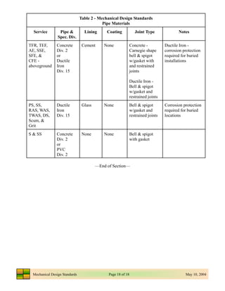

This document provides standards for mechanical design including piping systems, valves, pumps, and HVAC systems. It addresses general requirements for piping including pipe materials and sizes, supports, labeling, and corrosion protection. Process piping requirements include minimum pipe sizes, expansion joints, and sample taps. Chemical piping shall not be buried and be routed to prevent leaks from damaging other systems. Building service piping includes floor drains, sumps, and hose faucets for washdown.